Samsung SCC-B2315 User Manual
Wdr day/night colour camera
Hide thumbs
Also See for SCC-B2315:
- Specifications (1 page) ,
- User manual (162 pages) ,
- Specification sheet (6 pages)
Table of Contents
Advertisement
Available languages
Available languages
Advertisement
Chapters
Table of Contents

Related Manuals for Samsung SCC-B2315


Summary of Contents for Samsung SCC-B2315
- Page 1 WDR DAY/NIGHT COLOUR CAMERA SCC-B2315(P)/SCC-B2015P User Manual...
-
Page 2: Safety Precautions
9. If this product fails to operate normally, contact the nearest service centre. Never disassemble or modify this product in any way. (SAMSUNG is not liable for problems caused by unauthorized modifications or attempted repair.) 0. When cleaning, do not spray water directly onto parts of the product. - Page 3 CAUTION 1. Do not drop objects on the product or apply strong shock to it. Keep away from a location subject to excessive vibration or magnetic interference. 2. If you want to relocate the already installed product, be sure to turn off the power and then move or reinstall it.
-
Page 4: Important Safety Instructions
Important Safety Instructions Read these instructions. Keep these instructions. Heed all warnings. Follow all instructions. Do not use this apparatus near water. Clean only with dry cloth. Do not block any ventilation openings. Install in accordance with the manufacturer’s instructions. Do not install near any heat sources such as radiators, heat registers, or other apparatus (including amplifiers) that produce heat. -
Page 5: Table Of Contents
Contents IRIS ........20 Safety Precautions ..2 WDR........ 20 Important Safety ALC........21 Instructions ..... 4 ELC........22 Contents ......5 SHUTTER ......22 Overview ......6 ........23 Special Features ... 7 MOTION ......24 Part Names and MOTION DET .... -
Page 6: Overview
Overview This enriched WDR (Wide Dynamic Range) Day/Night camera can clearly implement both dark and bright parts on the screen with the dual shutter. When a bright object such as window occupies a part of the screen, it appears white in conventional cameras. But using the state-of-the-art WDR function that this camera provides, you can see the clear image. -
Page 7: Special Features
Special Features High Sensitivity It implements images of high sensitivity using the up-to-date Super- HAD P/S CCD. The WDR function of this camera is the state-of-the-art technology that can effectively enlarge the range for screen gain. It is mainly used for taking photos for window scenes inside a building. Using this technology, you can clearly see both indoor and outdoor images, and can enjoy the excellent picture quality, which is enabled by automatically adjusting the WDR level. -
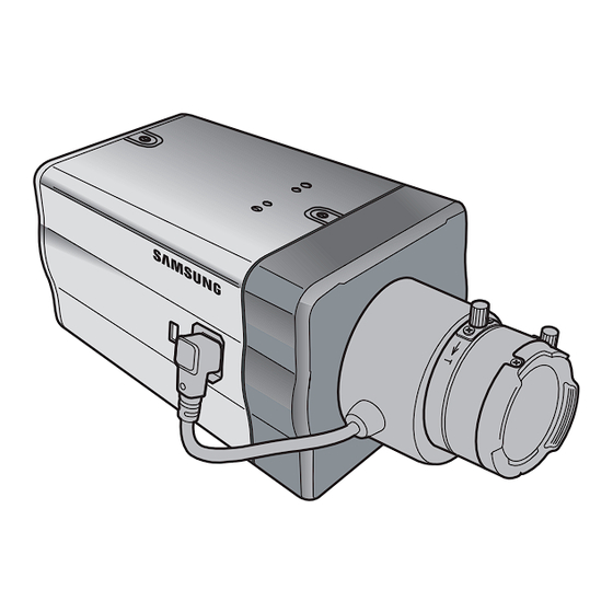
Page 8: Part Names And Functions
Part Names and Functions Side View ❚ 2 Mount Adapter 1 Auto Iris Lens Fixing Grooves Connector 3 Back Focus Control Bar 5 ALC Lens Selection Switch 4 Automatic Shutter Lens Control Cable Camera Lens 1 Auto Iris Lens Connector This groove is used for screwing the mount adapter, a part of the bracket where the camera will be installed. - Page 9 5 ALC Lens Selection Switch This switch is used to select the type of the Auto Iris lens for use. After this setting, you have to also set the lens type in the Setup menu (In ALC… and WDR… submenus of IRIS). DC: When the Auto Iris lens is installed for DC control ...
-
Page 10: Rear Panel
Rear Panel ❚ AC24/DC12V(SCC-B2315, B2315P) AC220V~240V(SCC-B2015P) - Page 11 1 Input/Output Connector This connector has input and output jacks for RS-485 control signals, Day & Night switching, and alarm output signals. Function Description RS-485 DATA+ Jack for connection to RS-485 DATA+ signal line. RS-485 DATA- Jack for connection to RS-485 DATA- signal line.
- Page 12 2 Setup Switch This switch is used to set the function or property. When this switch is pressed for at least 2 seconds, the Setup menu appears. [Left/Right] movement or changing the displayed value: By pressing this switch left or right, you can move left or right on the menu or change the displayed value.
-
Page 13: Installation
Installation Before Installation ❚ Checking the contents of the package Make sure that the following items are included in the package. Camera Camera Holder(Mount) Auto Iris User's Manual C Mount Adapter Lens Connector Things to keep in mind during installation and use Do not disassemble the camera on your own. -
Page 14: Connecting The Auto Iris Lens Connector
Connecting the Auto Iris Lens Connector The Auto Iris Lens Connector that is provided with your camera consists of the following parts: Connect each uncovered shutter control cables to the Auto Iris Lens Connector as the following: Pin No. DC Control Type Video Control Type Damp(-) Power (+12V) -
Page 15: Installing The Camera
Installing the Camera ❚ Mounting the lens When using the CS lens Mount the CS lens by rotating it clockwise as shown in the picture: CS lens When using the C lens After mounting the C-mount adapter by rotating it clockwise, turn the C lens clockwise until it is fixed as shown in the picture. -
Page 16: Setting The Alc Lens Selection Switch
Setting the ALC lens selection switch You can set the lens selection switch located on the side of the camera according to the lens type. When the mounted lens is an auto Iris lens of DC control type, set the switch to “DC.” When the mounted lens is an auto Iris lens of Video control type, set the switch to “VIDEO.”... -
Page 17: Connecting Cables And Checking Operation
Connecting cables and checking operation 1. Connect one end of the BNC cable to the VIDEO OUT jack on the rear of the camera. 2. Connect another end of the BNC cable to the VIDEO IN jack on the monitor. Video In Terminal of Monitor Rear Surface BNC cable... - Page 18 3. Finally connect the power adapter to the camera. You can connect 2 lines of the power adapter to the camera using the Slot Head screwdriver as shown in the picture. (GND: cable with the white stripe line) Note Connect any power source of AC 24V and DC 12V irrespective of polarity.
-
Page 19: Camera Setup
Camera Setup This chapter describes how to configure the camera-related settings. If you press the Setup switch for at least 2 seconds, the Setup menu appears. The Setup OSD (On-screen Display) map brief is like the following: ON... CAMERA ID WDR... -
Page 20: Camera Id
❚ CAMERA ID This CAMERA ID menu is used to assign a camera ID to this camera. If you press the Setup switch when the CAMERA ID menu is selected, the corresponding setup screen appears. CAMERA ID ON... IRIS ALC... (CAMERA ID) SHUTTER ABCDEFGHIJKLMNOPQRSTUVWXYZ... -
Page 21: Alc
CAMERA ID IRIS WDR... (WDR) SHUTTER HIGH MOTION DET DAY/NIGHT DAY... WHITE BAL ATW2 TYPE DC LENS PRIVACY LEVEL1 � � � I � � � SPECIAL LEVEL2 � � � I � � � RS-485 WHITE BAL INDOOR EXIT QUIT First select any of DC LENS, VIDEO LENS, and MANU in TYPE. -
Page 22: Elc
ELC... If you press the Setup switch when the ELC… submenu is selected, the corresponding screen appears. You can make the ELC (Elec- tronic Light Control) function active or not. CAMERA ID OFF... IRIS ELC... (ELC) SHUTTER HIGH MOTION DET ON... -
Page 23: Agc
If you keep pressing the LEFT/RIGHT Setup switch, shutter speeds toggles in the following order: OFF AUTO X2 AUTO X4 AUTO X6 AUTO X8 AUTO X12 AUTO X16 AUTO X24 AUTO X32 AUTO X48 ... -
Page 24: Motion
MOTION ❚ The MOTION menu is used to set the intensity of the camera AGC level for monitoring motions. This function is available only in AUTO low speed mode. You can select any of S.SLOW, SLOW, NORM, FAST, and F.FAST according to the AGC intensity level. CAMERA ID IRIS ALC... - Page 25 There are 3 different types like 1, 2, and 3. You cannot change the setting for type 2 because it is prefixed with the full screen. In case of 1 and 3, you can set the motion detection area on your own. Those 3 types are like the following: 1.
-
Page 26: Day/Night
3. Block type: The screen displays with small blocks. When a motion is detected in the selected blocks, the small blocks are displayed on the screen. PRESET: The whole screen becomes the motion detection area. USER...: You can manually set the motion detection area. ... -
Page 27: Day
Note In case of B/W mode, it may fail to focus when B/W mode is converted to Color mode. That is because it must have the condition to have IRIS opened for the maximum before adjusting the Back-Focus. The smaller the F number of lens is, the lower the focus depth of field is (e.g. -
Page 28: Night
NIGHT... If you press the Setup switch when the NIGHT… submenu is se- lected, the corresponding screen appears. (NIGHT) COLOR/BW COLOR... Even in night mode, you can see colour images in bright illumina- tion. Therefore you can select any of COLOUR… and BW… In case of COLOUR…, you have to set the colour temperature for white balance. -
Page 29: Ext
For this function, you can specify the level for each conversion between Day and Night. Note When the DAY/NIGHT is set to AUTO, the AGC is displayed with --- so you cannot change its setting. This automatically converts the colour mode to BW mode and vice versa by interfacing with an external sensor. -
Page 30: Privacy
ATW2: Its colour temperature variation range is approximately from 2000°K to 10000°K. AWC (Auto White Balance Control): The colour temperature setting is made once. After selecting this, expose to an object to memorize the colour temperature of it and press the Setup switch. -
Page 31: Special
PRIVACY 0 PRIVACY 16 < SIZE > < SIZE > < LOCATION > < LOCATION > TYPE COLOR COLOR EXIT QUIT EXIT QUIT <In case of selecting a zone on first page> <In case selecting a zone on second page> In case of type1, a box type zone is set while a diamond type zone is set for the type 2. -
Page 32: Digital Zoom
Note In case of LINE, it doesn’t support DC 12V, for which “---” is displayed. DIGITAL ZOOM You can set the level and ratio of digital zoom. If you press the Setup switch when ON… is selected in DIGITAL ZOOM, the corresponding screen appears. -
Page 33: Dnr
You can configure the DNR (Digital Noise Reduction) related set- tings. If you press the Setup switch when ON… is selected in DNR, the corresponding screen appears. (SPECIAL) (DNR) LANGUAGE ENGLISH V-SYNC DIGITAL ZOOM VIDEO SET ON... FLICKERLESS SYSTEM INFO LEVEL �... -
Page 34: System Info
(SPECIAL) (SYSTEM INFO) LANGUAGE ENGLISH ROM VER 1.000 V-SYNC EEP VER 1.000 DIGITAL ZOOM PROTOCOL SAMSUNG VIDEO SET ADDRESS TYPE RS-485, HALF FLICKERLESS BAUD RATE 9600 SERIAL NO. SYSTEM INFO 0000000000000 You can find the system information about ROM version, EEP version, protocol, address, type, baudrate, and serial number. -
Page 35: Exit
If you press the Setup switch when … is selected in the RS-485 menu, the corresponding screen appears. (RS-485) PROTOCOL SAMSUNG BAUD RATE 9600 ADDRESS You can set the protocol, baudrate, and address (range: 0 to 255) for this communication EXIT ❚... -
Page 36: Product Specifications
Details Product type CCTV Camera (WDR & DAY/NIGHT) Power source SCC-B2315: AC 24V ± 10% (60Hz ± 0.3 Hz), DC 12V +10%/-5% SCC-B2315P: AC 24V ± 10% (50Hz ± 0.3 Hz), DC 12V +10%/-5% SCC-B2015P: AC 220 to 240V ± 10% (50Hz ± 0.3 Hz) - Page 37 (3200°K, 5600°K, R/B Gain adjustment) Privacy ON/OFF Signal output Composite Video (1.0 Vp-p, 75ohm, BNC) AI lens VIDEO/DC Lens mount CS/C (Mount Adaptor) Operation -10°C~+50°C temperature Operation ~90% humidity Size 65(W) x 55(H) x 130.5(D)mm Weight SCC-B2315(P): Approx. 410g SCC-B2015P: Approx. 600g...
- Page 38 Memo...
- Page 39 Memo...
- Page 40 Correct Disposal of This Product (Waste Electrical & Electronic Equipment) (Applicable in the European Union and other European countries with separate collection systems) This marking shown on the product or its literature, indicates that it should not be disposed with other household wastes at the end of its working life.
- Page 41 WDR TAG/NACHT FARBKAMERA SCC-B2315(P)/SCC-B2015P Bedienungsanleitung...
- Page 42 Bedingungen weiterhin verwenden, kann Brand oder Elektroschock resultieren. Wenn dieses Produkt nicht einwandfrei funktioniert, wenden Sie sich an den nächstgelegenen Kundendienst. Zerlegen oder modifizieren Sie dieses Produkt nie in irgendeiner Weise. (SAMSUNG haftet nicht für Schäden, die durch unbefugte Änderungen oder Reparaturversuche verursacht werden.) 2 2 2...
- Page 43 10. Spritzen Sie während der Reinigung kein Wasser direkt auf die Produktteile. Dies führt sonst zu Brand oder Elektroschock.führt sonst zu Brand oder Elektroschock. VORSICHT Lassen Sie keine Gegenstände auf das Produkt fallen oder setzen Sie es keinen starken Stößen aus. Halten Sie sich fern von Standorten die übermäßiger Erschütterung oder magnetischer Beeinflussung ausgesetzt sind.
- Page 44 Wichtige Sicherheitshinweise Lesen Sie diese Anweisungen. Bewahren Sie sie auf. Beachten Sie alle Warnungen. Befolgen Sie alle Anweisungen. Verwenden Sie dieses Gerät nicht in der Nähe von Wasser. Reinigen Sie es nur mit einem trockenen Lappen. Blockieren Sie keine Belüftungsöffnungen. Installieren Sie es gemäß den Herstelleranweisungen.
- Page 45 Inhaltsangabe Sicherheitsvorsichtsma Kamera-Einstellung ..19 ßnahmen KAMERA ID ......2 ....20 Wichtige BLENDE ......20 Sicherheitshinweise WDR......20 ..4 Inhaltsangabe ALC........21 ....5 Übersicht ELC........22 ......6 Sonderfunktionen SHUTTER .......22 ..7 Teilenamen und .........23 Funktionen BEWEGUNG ....24 .....8 BEWEGUNGS- Seitenansicht ....8 ERKENNUNG Rückseitige Blende ....24...
-
Page 46: Übersicht
Übersicht Diese verbesserte WDR (Wide Dynamic Range) Tag/Nacht Kamera kann sowohl dunkle wie auch helle Teile am Bildschirm mit dem doppelten Verschluss deutlich implementieren. Wenn ein helles Objekt wie zum Beispiel ein Fenster einen Teil des Bildschirmes belegt, wird es in herkömmlichen Kameras weiß angezeigt. -
Page 47: Sonderfunktionen
Sonderfunktionen Hohe Empfindlichkeit Implementiert Bilder mit hoher Empfindlichkeit mithilfe des topaktuellen Super-HAD P/S CCD. Die WDR Funktion dieser Kamera ist die hypermoderne Technologie, die den Bereich für die Bildschirmverstärkung beträchtlich vergrößern kann. Sie wird hauptsächlich für die Aufnahme von Fotos bei Fensterszenen innerhalb eines Gebäudes verwendet. -
Page 48: Teilenamen Und Funktionen
Teilenamen und Funktionen Seitenansicht ❚ 2 Befestigungsaussparungen 1 Automatischer für Montageadapter Blendenobjektiv-Stecker 3 Regler für rückseitigen Fokus 5 Auswahlschalter für ALC Objektiv 4 Steuerkabel für Automatikverschluss- Objektiv Kameraobjektiv 1 Automatischer Irisobjektiv-Stecker Diese Aussparung dient für das Verschrauben des Montageadapters, ein Teil der Halterung, an den die Kamera montiert wird. - Page 49 5 ALC Objektiv-Auswahlschalter Mit diesem Schalter wählen Sie den automatischen Blendenobjektivtyp aus. Nach dieser Einstellung müssen Sie ebenfalls den Objektivtyp im Menü Einstellung (In ALC… und WDR… Untermenüs von BLENDE) festlegen. DC: Wird das automatische Blendenobjektiv für DC Steuersignale installiert, muss der Schalter auf “DC”gestellt werden.
-
Page 50: Rückseitige Blende
Rückseitige Blende ❚ AC24/DC12V(SCC-B2315, B2315P) AC220V~240V(SCC-B2015P) - Page 51 1 Eingangs-/Ausgangsstecker Dieser Stecker verfügt über Eingangs- und Ausgangsbuchsen für RS-485 Steuersignale, Tag- und Nachtumschaltung und Alarm-Ausgangssignale. Funktion Beschreibung RS-485 Buchsefür Anschluss an RS-485 DATEN+ DATEN+ Signalleitung. RS-485 DATEN- Buchse für Anschluss an RS-485 DATEN- Signalleitung. ALARM AUS Alarm Ausgang für Bewegungserkennung.
- Page 52 2 Schalter Einstellung Mit diesem Schalter wird die Funktion oder Eigenschaft festgelegt. Wird dieser Schalter mindestens 2 Sekunden lang gedrückt, wird das Menü Einstellung eingeblendet. [Links/Rechts] Verschiebung oder Ändern des angezeigten Wertes: Durch Drücken dieses Schalters nach links oder rechts, gelangen Sie am Menü nach links oder rechts oder Sie können auch den angezeigten Wert ändern.
-
Page 53: Installation
Installation Vor der Installation ❚ Überprüfen Sie den Inhalt der Verpackung Vergewissern Sie sich, dass folgende Artikel in der Verpackung enthalten sind . Kamerahalter (Halterung) Kamera Automatischer Bedienungsanleitung C Montageadapter Blenden- objektiv-Stecker Gebrauchs DemontierenSie die Kamera nicht. Geben Sie immer Acht, wenn Sie die Kamera ... -
Page 54: Anschluss Des Automatischen Blendenobjektiv-Steckers
Anschluss des automatischen Blendenobjektiv-Steckers Der automatische Blendenobjektiv-Stecker, der im Lieferumfang Ihrer Kamera enthalten ist, besteht aus folgenden Teilen: Schließen Sie jedes blanke Shutter-Steuerkabel wie folgt an den automatischen Blendenobjektiv-Stecker an: Steckerstift- DC Steuerungstyp Video Steuerungstyp Kondensation(-) Energie (+12V) Kondensation(+) Nicht zutreffend Ansteuerung(+) Videosignal Ansteuerung(-) -
Page 55: Installieren Der Kamera
Installieren der Kamera ❚ Montage des Objektivs Bei Verwendung des CS Objektivs Montieren Sie das CS Objektiv, indem Sie es im Uhrzeigersinn drehen, wie in der Abbildung dargestellt: CS Objektiv Bei Verwendung des C Objektivs Drehen Sie nach der Montage des C-Montageadapters durch Drehen im Uhrzeigersinn, das C Objektiv ebenfalls im Uhrzeigersinn bis es befestigt ist, wie in der Abbildung dargestellt. -
Page 56: Einstellung Des Auswahlschalters Für Das Alc Objektiv
Einstellung des Auswahlschalters für das ALC Objektiv Sie können den Auswahlschalter des Objektivs, der sich seitlich an der Kamera befindet, gemäß dem Objektivtyp einstellen. Stellen Sie den Schalter auf “DC”, wenn das montierte Objektiv ein automatisches Blendenobjektiv des Regelungstyps DC ist. Stellen Sie den Schalter auf “VIDEO”, wenn das montierte Objektiv ein automatisches Blende- nobjektiv des Regelungstyps Video ist. -
Page 57: Anschluss Der Kabel Und Funktionskontrolle
Anschluss der Kabel und Funktionskontrolle 1. Schließen Sie ein Ende des BNC-Kabels an die VIDEO AUS Buchse an der Rückseite der Kamera an. 2. Schließen Sie das andere Ende des BNC-Kabels an die VIDEO EIN Buchse am Monitor an. Video Ein Klemme der Monitor-Rückseite BNC-Kabel Video Aus Klemme... - Page 58 3. Schließen Sie dann das Netzkabel an die Kamera an. Schließen Sie die 2 Leitungen des Netzadapters mit dem Kreuzschlitzschra ubendreher an die Kamera an, wie in der Abbildung dargestellt. (GND: Kabel mit der weiß gestreiften Leitung) Hinweis: Schließen Sie eine AC 24V und DC 12V Stromquelle unabhängig von der Polarität an.
-
Page 59: Kamera-Einstellung
Kamera-Einstellung Dieses Kapitel beschreibt die Konfiguration der kamerabezogenen Einstellungen. Wenn Sie den Setup-Schalter mindestens 2 Sekunden lang gedrückt halten, wird das Setup-Menü eingeblendet. Die Kurzbeschreibung der Einstellung OSD (Bildschirmanzeige) ist wie folgt: EIN... KAMERA ID WDR... BLENDE ALC... ELC... SHUTTER AUTO X2 to X256 1/100 (oder 1/120) bis 1/10K WENIG... -
Page 60: Kamera Id
❚ KAMERA ID Mit diesem KAMERA ID Menü weisen Sie der Kamera eine Kamera ID zu. Wenn Sie den Schalter Einstellung bei Auswahl des KAMERA ID Menüs drücken, wird der entsprechende Einstellungsbildschirm eingeblendet. KAMERA ID EIN... BLENDE ALC... (KAMERA ID) SHUTTER ABCDEFGHIJKLMNOPQRSTUVWXYZ HOCH... -
Page 61: Alc
KAMERA ID BLENDE WDR... (WDR) SHUTTER HOCH BEWEGUNGSERKENNUNG TAG/NACHT TAG... WEISSABGL ATW2 TYPE DC OBJEKTIV PRIVAT PEGEL1 � � � I � � � SPEZIAL PEGEL2 � � � I � � � RS-485 WEISSABGL INDOOR AUSGANG VERL Wählen Sie zunächst entwederdas DC OBJEKTIV, VIDEO OBJEKTIV oder MANU unter TYPE Sie können die Verschluss geschwindigkeit unter PEGEL 1 und die Helligkeit unter PEGEL 2 einstellen. -
Page 62: Elc
ELC... Wird der Schalter Einstellung bei Auswahl des Untermenüs ELC… gedrückt, wird, der entsprechende Bildschirm eingeblendet. Sie können die Funktion ELC (Elektronische Lichtsteuerung) aktivieren oder nicht. KAMERA ID BLENDE ELC... (ELC) SHUTTER HOCH BEWEGUNGSERKENNUNG EIN... TAG/NACHT TAG... WEISSABGL ATW2 PRIVAT SPEZIAL RS-485 PEGEL... -
Page 63: Agc
Wenn Sie den LINKEN/RECHTEN Einstellungs- Schalter drücken, schaltet die Geschwindigkeit des Verschlusses in der folgenden Reihenfolge: AUS AUTO X2 AUTO X4 AUTO X6 AUTO X8 AUTO X12 AUTO X16 AUTO X24 AUTO X32 AUTO X48 ... -
Page 64: Bewegung
BEWEGUNG ❚ Mit dem Menü BEWEGUNG können Sie die Intensität des AGC Pegels der Kamera für die Überwachung von Bewegungen einstellen. Diese Funktion steht nur im AUTO Niedergeschwindigkeits-Modus zur Verfügung. Sie können zwischen S.LANGS, LANGS, NORM, SCHN und S.SCHN gemäß des AGC Intensitätspegels wählen. - Page 65 Es gibt 3 verschiedene Typen wie 1, 2 und 3. Sie können die Einstellung für Typ 2 nicht ändern, da er mit dem Vollbildschirm vorher festgelegt wird. Bei 1 und 3 können Sie den Bewegungserkennungs- bereich selbst einstellen. Diese 3 Typen sind wie folgt: 1.
-
Page 66: Tag/Nacht
3. Blocktyp: Bildschirmanzeigen mit kleinen Blöcken. Wenn eine Bewegung in den ausgewählten Blöcken erkannt wird, werden die kleinen Blöcke am Bildschirm angezeigt. VOREINSTELLUNG: Der gesamte Bildschirm wird der Bewegungserkennungsbereich. ANWENDER: Sie können den Bewegungserkennungsbereich manuell einstellen. Mit dem Schalter Einstellung AUF/AB/ LINKS/RECHTS stellen Sie den Bereich ein. -
Page 67: Tag
Hinweis: Beim S/W-Modus kann die Fokussierung fehlschlagen, wenn der S/W-Modus in den Farbmodus konvertiert wird. Das liegt daran, dass die Bedingung gegeben sein muss IRIS max. geöffnet zu haben, bevor Sie den rückseitigen Fokus einstellen. Je kleiner die F Nummer des Objektivs ist, desto niedriger ist die Fokustiefe des Bereiches. -
Page 68: Nacht
NACHT... Wenn Sie den Schalter Einstellung, bei Auswahl des Untermenüs NACHT… drücken, wird der entsprechende Bildschirm eingeblendet. (NACHT) FARBE/S/W FARBE... Selbst im Nachtmodus können Sie die Farbbilder bei heller Beleuchtung sehen. Deshalb können Sie zwischen FARBE… und SW… wählen. Bei FARBE…, müssen Sie die Farbtemperatur für den Weißabgleich einstellen. -
Page 69: Ext
Für diese Funktion können Sie den Pegel für die jeweilige Umwandlung zwischen Tag und Nacht festlegen. Hinweis: Wenn TAG/NACHT auf AUTO eingestellt ist, wird AGC damit angezeigt --- deshalb können Sie die Einstellung nicht ändern. Dies wandelt automatisch den Farbmodus auf SW Modus um und umgekehrt durch Kopplung mit einem externen Sensor. -
Page 70: Privat
ATW2: Der Farbtemperatur Abweichungsbereich ist ungefähr von 2.000°K bis 10.000°K. AWC (Auto Weißabgleichregelung): Die Farbtemperatureinst ellung wird einmal durchgeführt. Nach dieser Auswahl, richten Sie die Kamera auf ein Objekt, um dessen Farbtemperatur einzulesen. Drücken Sie dann den Schalter Einstellung. Die festgesetzte Farbtemperatur wird angewandt. -
Page 71: Spezial
PRIVAT 0 PRIVAT 16 < > GROESSE < > < POSITION > GROESSE < POSITION > TYPE FARBE FARBE AUSGANG VERL AUSGANG VERL <Bei Auswahl einer Zone auf der ersten Seite> <Bei Auswahl einer Zone auf der zweiten Seite> Im Falle von Typ1 wird eine kastenförmige Zone festgelegt, während eine diamantförmige Zone für Typ 2 festgelegt wird. -
Page 72: Digitaler Zoom
Hinweis: Im Falle von LINIE, wird DC 12V nicht unterstützt, für welches “---” angezeigt wird. DIGITAL ZOOM Sie können die Stufe und das Verhältnis des Digitalzoom festsetzen. Wenn Sie den Schalter Einstellung bei Auswahl von EIN… unter DIGITALER ZOOM drücken, wirdder entsprechendeBildschirm angezeigt. (SPEZIAL) (DIGITAL ZOOM) SPRACHE... -
Page 73: Dnr
Sie können die DNR-bezogenen (Digitale Rauschunterdrückung) Einstellungen konfigurieren. Wird der Schalter Einstellung bei Auswahl von EIN… im Menü DNR gedrückt, wird der entsprechende Bildschirm eingeblendet. (SPEZIAL) (DNR) SPRACHE DEUTSCH V-SYNC DIGITAL ZOOM VIDEO PROG EIN... FLIMMERFREI SYSTEM INFO PEGEL L� � � � I � � � � Sie können den Pegel für diese Konfiguration festsetzen. -
Page 74: System Info
(SPEZIAL) (SYSTEM INFO) SPRACHE DEUTSCH ROM VER 1.000 V-SYNC EEP VER 1.000 DIGITAL ZOOM PROTOKOLL SAMSUNG VIDEO PROG ADRESSE TYPE RS-485, HALB FLIMMERFREI BAUD RATE 9600 S/N: SYSTEM INFO 0000000000000 Sie finden hier die Systeminformationen über die ROM Version, EEP Version, Protokoll, Adresse, typ, Baudrate und Seriennummer. -
Page 75: Ausgang
Wird der Schalter Einstellung bei Auswahl von … im Menü RS-485 gedrückt, wird der entsprechende Bildschirm eingeblendet. (RS-485) PROTOKOLL SAMSUNG BAUD RATE 9600 ADRESSE Sie können das Protokoll, die Baudrate und die Adresse (Bereich: 0 bis 255) für diese Kommunikation festsetzen. -
Page 76: Produkt Spezifikationen
Artikel Details Produkttyp CCTV Kamera (WDR & TAG/NACHT) Energiequelle SCC-B2315: AC 24V ± 10% (60Hz ± 0.3 Hz), DC 12V +10%/-5% SCC-B2315P: AC 24V ± 10% (50Hz ± 0.3 Hz), DC 12V +10%/-5% SCC-B2015P: AC 220 to 240V ± 10% (50Hz ±... - Page 77 Weißabgleich ATW1/ATW2/AWC/MANUELLER Modus (3200°K, 5600°K, R/B Gain Einstellung) Privat EIN/AUS Signalausgabe Composite Video (1.0 Vp-p, 75ohm, BNC) AI Objektiv VIDEO/DC Objektivhalterung CS/C (Montage-Adaptor) Betriebstemperatur -10°C~+50°C Betriebsfeuchtigkeit ~90% Größe 65(B) x 55(H) x 130,5(T)mm Gewicht SCC-B2315(P): Circa 410g SCC-B2015P: Circa 600g...
- Page 78 Memo...
- Page 80 Korrekte Entsorgung von Altgeräten (Elektroschrott) (In den Ländern der Europäischen Union und anderen europäischen Ländern mit einem separaten Sammelsystem) Die Kennzeichnung auf dem Produkt bzw. auf der dazugehörigen Dokumentation gibt an, dass es nach seiner Lebensdauer nicht zusammen mit dem normalen Haushaltsmüll entsorgt werden darf. Entsorgen Sie dieses Gerät bitte getrennt von anderen Abfällen, um der Umwelt bzw.
- Page 81 WDR CAMERA COULEUR JOUR/NUIT SCC-B2315(P)/SCC-B2015P Guide d’utilisation...
- Page 82 Si ce produit ne fonctionne pas normalement, contactez le centre de maintenance le plus proche. Ne jamais démonter ou modifier le produit de quelque manière que ce soit. (SAMSUNG n’est pas responsable des problèmes causés par des modifications ou des tentatives de réparation non autorisées.) 10.
- Page 83 MISE EN GARDE Ne pas faire tomber des objets sur le produit ou lui faire subir des chocs. Eloignez le produit des emplacements soumis aux vibrations ou interférences magnétiques excessives. Si vous désirez changer le produit de place, assurez-vous de le mettre hors tension, déplacez-le et réinstallez-le.
- Page 84 Instructions importantes relatives à la sécurité Veuillez lire ces instructions. Conservez ces instructions. Prêtez attention à tous les avertissements. Veuillez suivre toutes les instructions. N’utilisez pas cet appareil à proximité de l’eau. Nettoyez-le avec un tissu sec. N’obstruez pas les ouvertures de ventilation. Procédez à l’installation conformément aux instructions du fabricant.
- Page 85 Sommaire Précautions de Réglage de la sécurité caméra ......2 ......19 Instructions CAMERA ID ....20 importantes relatives à IRIS ........20 la sécurité ....... 4 WDR....... 20 Sommaire ......5 ALC......... 21 Vue d’ensemble ... 6 ELC...
-
Page 86: Vue D'ensemble
Vue d’ensemble Cette caméra Jour/Nuit WDR (Wide Dynamic Range) améliorée est capable d’implémenter efficacement à la fois les zones claires et sombres de l’écran grâce à un double obturateur. Avec une caméra conventionnelle, lorsqu’ un objet lumineux, une fenêtre par exemple, occupe une portion importante de l’écran, cette zone apparaît en blanc. -
Page 87: Caractéristiques Spéciales
Caractéristiques spéciales Sensibilité élevée Elle implémente des images avec une sensibilité élevée grâce au Super-HAD P/S CCD le plus moderne. La fonction WDR de cette caméra est la technologie de pointe qui peut efficacement accroître la portée pour un gain à l’écran. Elle est principalement utilisée pour prendre des photos de scènes incluant des fenêtres à... -
Page 88: Nom Des Pièces Et Fonctions
Nom des pièces et fonctions Vue latérale ❚ 1 Connecteur 2 Trous de fixation du objectif Auto Iris socle de fixation 3 Levier de commande de la focale minimale 5 Sélecteur de l’objectif ALC 4 Câble de commande de l’obturateur automatique de l’objectif Objectif de la caméra 1 Connecteur Objectif Iris Auto... - Page 89 5 Sélecteur de l’objectif ALC Ce sélecteur sert à sélectionner le type d’objectif Auto Iris à utiliser. Une fois ce réglage effectué, vous devez également régler le type d’objectif dans le menu Réglages (Dans ALC ... et WDR...sous-menus de IRIS). DC : Lorsque l’objectif Auto Iris est installé...
-
Page 90: Panneau Arrière
Panneau arrière ❚ AC24/DC12V(SCC-B2315, B2315P) AC220V~240V(SCC-B2015P) - Page 91 1 Connecteur Entrée/Sortie Ce connecteur est muni d’entrées et de sorties jack pour les signaux de commande RS-485, la commutation Jour/Nuit, et les signaux de sortie d’alarme. Fonction Description RS-485 Jack pour la connexion à RS-485 DONNEES+ DONNEES+ ligne de signal. RS-485 Jack pour la connexion à...
- Page 92 2 Commutateur Réglage Ce commutateur sert à régler la fonction ou la propriété. Lorsque l’on appuie plus de 2 secondes sur ce commutateur, le menu Réglage apparaît. Mouvement [Gauche/Droite] ou changement de la valeur affichée : En déplaçant ce commutateur à gauche ou à droite, vous pouvez vous déplacer à...
-
Page 93: Installation
Installation Avant l’installation ❚ Vérification du contenu de l’emballage Assurez-vous que l’emballage contient bien les éléments suivants. Caméra Support de caméra (Socle) Adaptateur pour Auto Iris Guide d’utilisation Connecteur d’objectif objectif C Pendant l’installation et l’utilisation, n’oubliez pas : Ne démontez pas la caméra vous-même. ... -
Page 94: Connexion Du Connecteur D'objectif Auto Iris
Connexion du connecteur d’objectif Auto Iris Le Connecteur d’objectif Auto Iris fourni avec votre caméra, se compose des pièces suivantes : Connectez comme suit chacun des fils dénudés des commandes d’obturateur au connecteur d’objectif Auto Iris : Broche Type de commande Type de commande vidéo Amortir(-) Alimentation (+12V) -
Page 95: Installation De La Caméra
Installation de la caméra ❚ Montage de l’objectif Lors de l’utilisation de l’objectif CS Monter l’objectif CS en le faisant tourner dans le sens horaire comme indiqué sur l’image : Objectif CS Lors de l’utilisation de l’objectif C Après avoir monté l’adaptateur pour objectif C en le faisant tourner dans le sens horaire, faites pivoter l’objectif C dans le sens horaire jusqu’à... -
Page 96: Réglage Du Commutateur De Sélection De L'objectif Alc
Réglage du commutateur de sélection de l’objectif ALC Vous pouvez régler le sélecteur de l’objectif situé sur le coté de la caméra en fonction du type d’objectif. Lorsque l’objectif monté est un objectif type Auto Iris à type de commande DC, positionnez le sélecteur sur “DC”. -
Page 97: Connexion Des Câbles Et Opération De Vérification
Connexion des câbles et opération de vérification 1. Connectez une extrémité du câble BNC au jack SORTIE VIDEO situé à l’arrière de la caméra. 2. Connectez l’autre extrémité du câble BNC au jack ENTREE VIDEO sur le moniteur. Vidéo sur le terminal de Surface arrière du moniteur Câble BNC... - Page 98 3. Enfin, connectez l’adaptateur secteur à la caméra. Vous pouvez connecter 2 lignes de l’adaptateur secteur à la caméra à l’aide d’un tournevis plat comme indiqué sur l’image. (Masse : câble à rayures) Note : Connectez une source d’alimentation de 24V (Courant alternatif) et 12V (Courant continu) sans tenir compte de la polarité.
-
Page 99: Réglage De La Caméra
Réglage de la caméra Ce chapitre décrit comment configurer les réglages relatifs à la caméra. Lorsque l’on appuie plus de 2 secondes sur le commutateur Réglage, le menu Réglage apparaît. La carte du réglage OSD (Affichage à l’écran) se présente comme suit : ON... -
Page 100: Camera Id
❚ CAMERA ID Ce menu CAMERA ID sert à affecter un nom à cette caméra. Si vous appuyez sur le commutateur Réglage lorsque le menu CAMERA ID est sélectionné, l’écran de réglage correspondant apparaît. CAMERA ID ON... IRIS ALC... (CAMERA ID) SHUTTER ABCDEFGHIJKLMNOPQRSTUVWXYZ HAUT... -
Page 101: Alc
CAMERA ID IRIS WDR... (WDR) SHUTTER HAUT DET MOUVE JOUR/NUIT JOUR... BAL BLANCS BA 2 TYPE DC OBJECTIF PRIVEE NIVEAU1 � � � I � � � SPECIAL NIVEAU2 � � � I � � � RS-485 BAL BLANCS INDOOR SORTIE QUITTER Commencez par sélectionner parmi : DC OBJECTIF, VIDEO... -
Page 102: Elc
ELC... Si vous appuyez sur le commutateur Réglage lorsque le sous-menu ELC... est sélectionné, l’écran correspondant apparaît. Vous pouvez rendre la fonction ELC (Commande électronique de la lumière) active ou inactive. CAMERA ID IRIS ELC... (ELC) SHUTTER HAUT DET MOUVE ON... -
Page 103: Cag
Si vous maintenez le commutateur de réglage GAUCHE/DROITE Réglage, les vitesses de l’obturateur défilent dans l’ordre suivant : OFF AUTO X2 AUTO X4 AUTO X6 AUTO X8 AUTO X12 AUTO X16 AUTO X24 AUTO X32 AUTO X48 ... -
Page 104: Mouve
MOUVE ❚ Le menu MOUVE sert à régler l’intensité du niveau CAG de la caméra pour surveiller des mouvements. Cette fonction n’est disponible qu’avec le mode basse vitesse AUTO. Vous pouvez sélectionner parmi : T.LENT, LENT, NORM, VITE, et T.VITE en fonction du niveau d’intensité... - Page 105 Ces 3 types sont comme suit : 1. Type fenêtre : La zone sélectionnée s’affiche dans un carré. La détection de mouvements se fait pour la zone uniquement. Vous pouvez régler manuellement la zone de détection de mouvements. Vous pouvez utiliser le commutateur de réglage HAUT/BAS/GAUCHE/DROITE pour régler la taille.
-
Page 106: Jour/Nuit
3. Type bloc : L’écran affiche de petits blocs. Lorsqu’un mouvement est détecté dans les blocs sélectionnés, ces derniers s’affichent sur l’écran. PRESET: L’écran entier devient la zone de détection de mouvements. UTIL...: Vous pouvez régler manuellement la zone ... -
Page 107: Jour
Note : En cas de N/B, la mise au point risque d’échouer lors de la conversion du mode N/B en mode Couleur. Ceci parce que le DIAPHRAGME doit être ouvert au maximum avant le réglage du foyer arrière. Plus le nombre F de l’objectif est petit, plus la profondeur de foyer est basse.(p.ex. -
Page 108: Nuit
NUIT... Si vous appuyez sur le commutateur Réglage lorsque le sous-menu NUIT... est sélectionné, l’écran correspondant apparaît. (NUIT) COULEUR/N&B COULEUR... Même en mode nuit, vous pouvez voir des images en couleur avec une bonne luminosité. Par conséquent, vous pouvez sélectionner COULEUR…... -
Page 109: Ext
Pour cette fonction, vous pouvez spécifier le niveau pour chaque conversion entre Nuit et Jour. Note : Lorsque JOUR/NUIT est réglé sur AUTO, le CAG s’affiche avec --- et vous ne pouvez donc pas changer son réglage. Convertit automatiquement le mode couleur en mode N&B et in- versement en servant d’interface avec le capteur externe. -
Page 110: Privee
BA2: La plage de variation de la température des couleurs s’étend de 2 000°K à 10 000°K. AWC (Commande automatique de la balance des blancs) : Le réglage de la température des couleurs s’effectue une fois. Après l’avoir sélectionné, exposez un objet pour mémoriser sa température de couleur et appuyez sur le commutateur Réglage. -
Page 111: Special
PRIVEE 16 PRIVEE 0 < TAILLE > < POSITION > < > TAILLE < POSITION > TYPE COULEUR COULEUR SORTIE QUITTER SORTIE QUITTER <Si vous sélectionnez une zone sur la <Si vous sélectionnez une zone sur la première page> deuxième page> Dans le cas d’un type 1, une zone de forme carrée est réglée alors qu’une zone en forme de diamant est réglée pour le type 2. -
Page 112: Zoom Digital
Note : Si vous choisissez LIGNE, l’alimentation DC 12V (Courant continu) n’est pas supportée et “---” s’affiche. ZOOM DIGITAL Vous pouvez régler le niveau et le rapport du zoom digital. Si vous appuyez sur le commutateur Réglage lorsque ON… est sélectionné dans ZOOM DIGITAL, l’écran correspondant apparaît. -
Page 113: Dnr
Vous pouvez configurer les réglages relatifs à la DNR (Réduction digitale du bruit). Si vous appuyez sur le commutateur Réglage lorsque ON… est sélectionné dans DNR, l’écran correspondant apparaît. (SPECIAL) (DNR) LANGAGE FRANÇAIS V-SYNC ZOOM DIGITAL PROG VIDEO ON... ANTI-BATTEMENT INFO SYSTEME NIVEAU L�... -
Page 114: Info Systeme
(SPECIAL) (INFO SYSTEME) LANGAGE FRANÇAIS VER. ROM 1.000 V-SYNC VER. EEP 1.000 ZOOM DIGITAL PROTOCOLE SAMSUNG PROG VIDEO ADRESSE TYPE RS-485, DEMI ANTI-BATTEMENT VITESSE 9600 SERIE NO INFO SYSTEME 0000000000000 Vous pouvez trouver des informations concernant la version ROM, la version EEP, le protocole, l’adresse, le type, la vitesse et le numéro... -
Page 115: Sortie
Si vous appuyez sur le commutateur Réglage lorsque … est sélectionné dans le menu RS-485, l’écran correspondant apparaît. (RS-485) PROTOCOLE SAMSUNG VITESSE 9600 ADRESSE Vous pouvez sélectionner le protocole, la vitesse, et l’adresse (plage : 0 à 255) pour cette communication SORTIE ❚... -
Page 116: Spécifications Du Produit
Elément Détails Type de produit Caméra de surveillance (WDR & JOUR/NUIT) Source SCC-B2315: AC 24V ± 10% (60Hz ± 0.3 Hz), d’alimentation DC 12V +10%/-5% SCC-B2315P: AC 24V ± 10% (50Hz ± 0.3 Hz), DC 12V +10%/-5% SCC-B2015P: AC 220 à 240V ± 10% (50Hz ±... - Page 117 Sortie de signal Vidéo composite (1,0 Vp-p, 75ohm, BNC) Objectif Al VIDEO/DC Monture d’objectif CS/C (Adaptateur de monture) Température -10°C~+50°C d’utilisation Humidité lors de ~90% l’utilisation Taille 65(W) x 55(H) x 130,5(D)mm Poids SCC-B2315(P) : env. 410g SCC-B2015P : Env. 600g...
- Page 118 Mémo...
- Page 120 Comment éliminer ce produit (déchets d’équipements électriques et électroniques) (Applicable dans les pays de l’Union Européen et aux autres pays européens disposant de systémes de collecte sélective) Ce symbole sur le produit ou sa documentation indique qu’il ne doit pas être éliminé...
- Page 121 CÁMARA DE COLOR DIA/NOCHE WDR SCC-B2315(P)/SCC-B2015P Manual de usuario...
-
Page 122: Precauciones De Seguridad
Si este producto deja de funcionar con normalidad, póngase en contacto con el servicio técnico más cercano. Nunca intente desmontar o modificar este producto de ninguna manera. (SAMSUNG no se hace responsable de los problemas producidos por modificaciones no autorizadas o por intentos de reparaciones.) - Page 123 PRECAUCIÓN No deje objetos sobre el producto ni aplique una fuerte presión sobre él. Manténgalo lejos de lugares sujetos una demasiadas vibraciones o a interferencias magnéticas. Si desea cambiar de ubicación el aparato ya instalado, asegúrese de desconectar el suministro de energía. Una vez esté desconectado, mueva el aparato o vuelva a instalarlo. Desconecte el enchufe de la toma de corriente cuando hay rayos.
- Page 124 Instrucciones de seguridad importantes Lea estas instrucciones. Consérvelas. Preste atención a todas las advertencias. Siga todas las instrucciones. No utilice este aparato cerca del agua. Límpielo únicamente con un paño seco. No obstruya ninguna abertura de ventilación. Instale el aparato siguiendo las instrucciones del fabricante.
-
Page 125: Índice
Índice Precauciones de CÁMARA ID ......20 seguridad DIAFRAGMA ...... 20 ......2 Instrucciones de WDR....... 20 seguridad importantes ALC......... 21 ... 4 Índice ELC......... 22 ........5 Perspectiva general OBTURADOR ..... 22 ..6 Características ........ -
Page 126: Perspectiva General
Perspectiva general Esta cámara de día/noche enriquecida con WDR (Wide Dynamic Range) puede poner en funcionamento tanto las partes oscuras como las claras en la pantalla gracias al doble obturador. En las pantallas de las cámaras convencionales un objeto claro como una ventana se ve blanco. -
Page 127: Características Especiales
Características especiales Sensibilidad alta La cámara realiza imágenes de gran sensibilidad utilizando el Super-HAD P/S CCD actualizado de última generación . La función WDR de esta cámara es la tecnología de última generación que puede aumentar eficazmente el alcance del aumento de pantalla. -
Page 128: Piezas Y Funciones
Piezas y funciones Vista lateral ❚ 2 Ranuras de fijación del adaptador de 1 Conector de soporte lente de iris 3 Barra de control del automática enfoque posterior 5 Conmutador de selección de lentes ALC 4 Cable de control de obturador de lente automático Lentes de la cámara 1 Conector de objetivo de iris automático... - Page 129 5 Conmutador de selección de lentes ALC Se utiliza para seleccionar el tipo de lente de iris automático que se va a utilizar. Después de este ajuste, también tiene que configurar el tipo de lente en el menu de Configuracion (En ALC...
-
Page 130: Panel Posterior
Panel posterior ❚ AC24/DC12V(SCC-B2315, B2315P) AC220V~240V(SCC-B2015P) - Page 131 1 Conector de entrada/salida Este conector tiene tomas de entrada y salida para señales de control RS-485, conmutadores Día y Noche, y señales de salida de la alarma. Núm. Función Descripción RS-485 DATA+ Toma para conexión a la línea de señal RS- 485 DATA+.
- Page 132 2 Conmutador de configuración Este conmutador se utiliza para configurar la función o propiedad. Cuando se pulsa este conmutador durante al menos 2 segundos, aparece el menú de Configuración. movimiento [izquierda/derecha] o cambiar el valor que se muestra: Pulsando este conmutador hacia la izquierda o derecha, se desplazará...
-
Page 133: Instalación
Instalación Antes de la instalación ❚ Comprobar el contenido del paquete Asegúrese de que los siguientes elementos están en el paquete. Cámara Soporte de la cámara Conector de lente Manual de usuario C Adaptador del soporte iris automática Aspectos que se deben tener en cuenta durante la Instalación y su posterior empleo No desmonte la cámara por su cuenta. -
Page 134: Conectar El Conector De La Lente Iris Automática
Conectar el conector de la lente iris automática The El conector de la lente iris que se suministra con su cámara consta de las siguientes piezas: Conecte cada cable de control del obturador descubierto al conector de la lente iris automática siguiendo estos pasos: Núm. -
Page 135: Instalar La Cámara
Instalar la cámara ❚ Montar la lente Cuando utilice la lente CS Monte la lente CS girándola en el sentido de las agujas del reloj, tal y como se muestra en la figura: Lente CS Cuando utilice la lente C Después de montar el adaptador del soporte C girándolo en el sen- tido de las agujas del reloj, gire la lente C en el sentido de las agujas del reloj hasta que esté... -
Page 136: Configuración Del Conmutador De Selección De Lente Alc
Configuración del conmutador de selección de lente ALC Puede configurar el conmurador de selección de lente situado en el lateral de la cámara dependiendo del tipo de lente. Cuando la lente montada sea una lente de iris automática del tipo de control DC, coloque el conmutador en “DC.”... -
Page 137: Conexión De Los Cables Y
Conexión de los cables y comprobación de funcionamiento 1. Conecte un extremo del cable BNC a la toma SALIDA DE VÍDEO en el panel posterior de la cámara. 2. Conecte el otro extremo del cable BNC a la toma ENTRADA DE VÍDEO en el monitor. - Page 138 3. Por último, conecte el adaptador de potencia a la cámara. Puede conectar 2 líneas del adaptador de potencia a la cámara utilizando el destonillador de punta plana como se muestran en la figura. (Toma a tierra: cable con la línea blanca) Nota Conecte la fuente de alimentación de CA a 24 V y DC 12 V independientemente de la polaridad.
-
Page 139: Configuración De La Cámara
Configuración de la cámara En este capítulo se describe la forma de ajustar las configuraciones de la cámara. Si pulsa el conmutador de configuración durante al menos 2 segundos, aparecerá el menú de configuración. El mapa de configuración OSD (Visualización en pantalla) es el siguiente: ACTIVAR... -
Page 140: Cámara Id
❚ CÁMARA ID Este menú de CÁMARA ID se utiliza para asignar un identificador a la cámara. Si pulsa el conmutador Configuración cuando esté seleccionado el menú de CÁMARA ID, aparecerá la correspondiente pantalla de configuración. CÁMARA ID ACTIVAR... DIAFRAGMA ALC... -
Page 141: Alc
CÁMARA ID APAGAR DIAFRAGMA WDR... (WDR) OBTURADOR APAGAR ALTO DET MOVI APAGAR DIA/NOCHE DIA... BAL BLANCO TIPO ÓPTICA DC PRIVADA APAGAR NIVEL1 � � � I � � � ESPECIAL NIVEL2 � � � I � � � RS-485 BAL BLANCO INTERIOR SALIDA SALIR... -
Page 142: Elc
ELC... Si pulsa el conmutador de Configuración cuando el submenú ELC... esté seleccionado, aparecerá la pantalla correspondiente. Pu- ede activar o desactivar la función ELC (control electrónico de luz). CÁMARA ID APAGAR DIAFRAGMA ELC... (ELC) OBTURADOR APAGAR ALTO DET MOVI ACTIVAR... -
Page 143: Cag
Si continúa pulsando el conmutador de Configuración de DERECHA/ IZQUIERDA, la velocidad del obturador conmuta en el siguiente orden: APAGAR AUTO X2 AUTO X4 AUTO X6 AUTO X8 AUTO X12 AUTO X16 AUTO X24 AUTO X32 AUTO X48 ... -
Page 144: Movimiento
MOVIMIENTO ❚ El menú MOVIMIENTO se utiliza para configurar la intensidad del nivel CAG de la cámara para controlar los movimientos. Está función está disponible sólo en el modo automático de baja velocidad. Puede seleccionar M.DULC, DULC, NORM, RÁPIDO y R.RÁPIDO dependiendo del nivel de intensidad de CAG. - Page 145 Hay 3 tipos diferentes denominados 1, 2 y 3. No puede cambiar la configuración del tipo 2 porque está predeterminada para la pantalla completa. En los caso 1 y 3, puede configurar por su cuenta la zona de detección de movimiento. Estos 3 tipos se describen a continuación: 1.
-
Page 146: Dia/Noche
3. Tipo bloque: La pantalla se muestra con pequeños bloques. Cuando se detecta un movimiento en los bloques seleccionados, aparecen pequeños bloques en la pantalla. PRESET: La pantalla completa se convierte en el área de detección de movimiento. UTIL...: Puede configurar manualmente el área de ... -
Page 147: Dia
Nota En caso del modo ByN, podría no enfocar correctamente si el modo ByN se convierte en modo a color. Se debe a que tiene que darse la condición de disponer del IRIS abierto al máximo antes de ajustar el enfoque posterior. Cuanto menor sea el número F de lentes, menor será... -
Page 148: Noche
NOCHE... Si pulsa el conmutador de Configuración cuando el submenú NOCHE… está seleccionado, aparecerá la pantalla correspondiente. (NOCHE) COLOR/ByN COLOR... Incluso en el modo noche, puede ver las imágenes de color con una iluminación clara. Por tanto, puede seleccionar COLOR… o ByN… En el caso de COLOR…, tiene que determinar la temperatura del color para balance de blancos. -
Page 149: Ext
Para esta función puede especificar el nivel para cada conversión entre Día y Noche. Nota Cuando DIA/NOCHE está fijado en AUTO, aparece también CAG --- así que no puede variar su configuración. Convierte automáticamente el modo color en modo ByN y viceversa relacionándose con un sensor externo. -
Page 150: Privada
BA2: Su ámbito de variación de la temperatura del color varía aproximadamente entre 2.000°K (1.727 ºC) y 10.000°K (9.727 ºC). BA (Control de balance de blancos automático): La configuración de la temperatura del color se hace una vez. Después de seleccionarla, exponer a un objeto para memorizar la temperatura de éste y pulse el conmutador Configuración. -
Page 151: Especial
PRIVADA 0 PRIVADA 16 < DIMENSION > < DIMENSION > < POSICIÓN > < POSICIÓN > TIPO COLOR COLOR SALIDA SALIR SALIDA SALIR <En caso de seleccionar una zona en la <En caso de seleccionar una zona en la primera página> segunda página>... -
Page 152: Zoom Digital
Nota En caso de LNEA, no admite DC 12 V, para lo que se muestra “---”. ZOOM DIGITAL Puede configurar el nivel y la proporción del zoom digital. Si pulsa el conmutador Configuración cuando esté seleccionado ACTIVAR… en ZOOM DIGITAL, aparece rá la pantalla correspondiente. (ESPECIAL) (ZOOM DIGITAL) IDIOMA... -
Page 153: Rdr
Puede fijas las configuraciones relacionadas con RDR (reducción digital del ruido). Si pulsa el conmutador Configuración cuando esté selec- cionado ACTIVAR... en RDR, aparecerá la pantalla correspondiente. (ESPECIAL) (RDR) IDIOMA ESPAÑOL V-SINC ZOOM DIGITAL APAGAR PROG VIDEO ACTIVAR... OSCILACION RED APAGAR INFOR. -
Page 154: Infor. Sistema
INFOR. SISTEMA, aparecerá la pantalla correspondiente. (ESPECIAL) (INFOR. SISTEMA) IDIOMA ESPAÑOL VERS. ROM 1.000 V-SINC VERS. EEP 1.000 ZOOM DIGITAL APAGAR PROTOCOLO SAMSUNG PROG VIDEO DIRECCIÓN APAGAR TIPO RS-485, HALF OSCILACION RED APAGAR VELOCIDAD 9600 NUM. SERIE INFOR. SISTEMA 0000000000000 Puede encontrar la información del sistema sobre la versión ROM,... -
Page 155: Salida
Si pulsa el conmutador Configuración cuando esté seleccionado ... en el menú RS-485, aparecerá la página correspondiente. (RS-485) PROTOCOLO SAMSUNG VELOCIDAD 9600 DIRECCIÓN Puede configurar el protocolo, la velocidad en baudios y la dirección (entre 0 y 255) para esta comunicación SALIDA ❚... -
Page 156: Especificaciones Técnicas
Elemento Detalles Tipo de producto Cámara CCTV (WDR y DIA/NOCHE) Fuente de SCC-B2315: AC 24V ± 10% (60Hz ± 0.3 Hz), alimentación DC 12V +10%/-5% SCC-B2315P: AC 24V ± 10% (50Hz ± 0.3 Hz), DC 12V +10%/-5% SCC-B2015P: AC 220 a 240V ± 10% (50Hz ±... - Page 157 Vídeo compuesto (1.0Vp-p, 75ohm, BNC) Lente AI VÍDEO/DC Soporte de lente CS/C (Adaptador de soporte) Temperatura de -10°C~+50°C funcionamiento Humedad de ~90% funcionamiento Tamaño 65 (A) x 55 (L) x 130,5 (D) mm Peso SCC-B2315(P): Aprox. 410g SCC-B2015P: Aprox. 600g...
- Page 158 Notas...
- Page 160 Eliminación correcta de este producto (material eléctrico y electrónico de descarte) (Aplicable en la Unión Europea y en países europeos con sistenmas de recogida selectiva de residuos) La presencia de esta marca en el producto o en el material informativo que lo acompaña, indica que al finalizar su vida útil no deberá...
- Page 161 TELECAMERA A COLORI WDR GIORNO/NOTTE SCC-B2315(P)/SCC-B2015P Manuale d’uso...
- Page 162 Se il prodotto non funzionasse in modo normale, mettersi in contatto con il centro di assistenza più vicino. Non smontare o riparare in alcun modo questo prodotto. (SAMSUNG non è responsabile per problemi causati da modifiche non autorizzate o tentativi di riparazione)
- Page 163 10. Quando si pulisce, non spruzzare acqua direttamente sulle parti del prodotto. Ciò può causare incendi o scosse elettriche. ATTENZIONE Non far cadere oggetti sul prodotto ed evitare colpi forti. Mantenere lontano da luoghi sottoposti ad eccessive vibrazioni o ad interferenze magnetiche. Se si desidera modificare l’ubicazione del prodotto già...
- Page 164 Istruzioni di Sicurezza Importanti Leggere queste istruzioni. Conservare queste istruzioni. Rispettare tutti gli avvertimenti. Seguire tutte le istruzioni. Non utilizzare questo apparecchio vicino all’acqua. Pulire solo con un panno asciutto. Non bloccare nessuna apertura di ventilazione. Istallare seguendo le istruzioni del fabbricante. Non istallare vicino a fonti di calore quali caloriferi, stufe o altri prodotti (compresi gli amplificatori) che possano produrre calore.
-
Page 165: Indice
Indice Precauzioni di Impostazione sicurezza videocamera ......2 ....19 Istruzioni di Sicurezza ID TELECAMERA ..20 Importanti DIAFRAMMA ......4 ....20 Indice .......5 WDR......20 Introduzione ....6 ALC ......21 Caratteristiche ELC ......22 speciali SHUTTER ......7 ....22 Nomi e funzioni delle ......23 parti MOVIMENTO ........8... -
Page 166: Introduzione
Introduzione Questa nuova telecamera WDR (Wide Dynamic Range) Giorno/ Notte può migliorare in modo evidente la qualità sia delle parti buie sia di quelle luminose sullo schermo con l’otturatore duale. Quando un oggetto luminoso, come ad esempio una finestra, occupa una parte dello schermo, con le telecamere convenzionali appare bianca. -
Page 167: Caratteristiche Speciali
Caratteristiche speciali Alta sensibilità Miglioramento della sensibilità utilizzando l’innovativo sensore CCD Super-HAD P/S CCD. La funzione WDR utilizzata in questa telecamera rappresenta il livello più avanzato della tecnologia. Questa funzionalità è utilizzata soprattutto per riprese in forte controluce come per esempio la ripresa di un soggetto alla finestra ripreso dall’interno di un edificio. -
Page 168: Nomi E Funzioni Delle Parti
Nomi e funzioni delle parti Vista Laterale ❚ 2 Fori di fissaggio adattatore di montaggio 1 Connettore obiettivo a diaframma automatico 3 Barra di controllo profondità di campo 5 Levetta di selezione ALC 4 Cavo di controllo otturatore automatico obiettivo Obiettivo della telecamera 1 Obiettivo a diaframma automatico Questo foro è... - Page 169 5 Levetta obiettivo ALC Questa levetta viene utilizzata per selezionare il tipo di obiettivo a diaframma automatico da utilizzare. Dopo questa impostazione, occorre impostare il tipo di obiettivo anche nel menu Impostazione (nei sottomenu ALC… e WDR… di DIAFRAMMA). DC: Quando l’obiettivo a diaframma automatico è ...
- Page 170 Pannello Posteriore ❚ AC24/DC12V(SCC-B2315, B2315P) AC220V~240V(SCC-B2015P)
- Page 171 1 Connettore Entrata/Uscita Questo connettore dispone di ingressi e di uscite, composte da segnali di controllo per RS-485, di comadi per la funzione Giorno/Notte e di comandi d’allarme. Funzione Descrizione RS-485 DATA+ Terminale per il collegamento del segnale RS-485 DATA+. RS-485 DATA- Terminale per il collegamento del segnale RS-485 DATA-.
- Page 172 2 Tasto impostazione Questo tasto è utilizzato per impostare la funzione o proprietà. Quando viene premuto per almeno 2 secondi, appare il menu Impostazione. Movimento [Sinistra/Destra] o cambio del valore visualizzato: Premendo il tasto destra o sinistra, è possibile muoversi a destra o a sinistra nel menu o cambiare il valore visualizzato.
-
Page 173: Istallazione
Istallazione Prima dell’istallazione ❚ Controllare il contenuto della confezione Assicurarsi che nella confezione siano inclusi i seguenti articoli. Telecamera Supporto Telecamera (Montaggio) C adattatore Manuale d’uso Diaframma automatico Connettore obiettivo montaggio Cose da ricordare durante l’istallazione e l’uso Non smontare la telecamera da soli. ... -
Page 174: Collegamento Del Connettore Dell'obiettivo A Diaframma Automatico
Collegamento del connettore dell’obiettivo a diaframma automatico Il connettore obiettivo a diaframma automatico fornito con la telecamera è formato dalle seguenti parti: Collegare ciascun cavo di controllo dell’otturatore libero al connettore obiettivo a diaframma automatico come segue: Nº Pin Tipo di controllo DC Tipo di controllo Video Damp (-) Alimentazione (+12V) -
Page 175: Istallazione Della Telecamera
Istallazione della telecamera ❚ Montare l’obiettivo Quando si utilizza l’obiettivo CS Montare l’obiettivo CS ruotandolo in senso orario come mostrato nell’immagine: Obiettivo CS Quando si utilizza l’obiettivo C Dopo aver montato l’adattatore di montaggio C ruotandolo in senso orario, girare l’obiettivo C in senso orario fin a fissarlo come indicato nell’immagine. -
Page 176: Impostare La Leva Dell'obiettivo Alc
Impostare la leva dell’obiettivo ALC Posizionare la leva obiettivo situata sul lato della telecamera in base al tipo di obiettivo. Quando l’obiettivo montato è un obiettivo a diaframma automatico a controllo DC, impostare la leva su “DC.” Quando l’obiettivo montato è un obiet- tivo a diaframma automatico a controllo Video, impostare la leva su “VIDEO”. -
Page 177: Collegare I Cavi E Controllare Il Funzionamento
Collegare i cavi e controllare il funzionamento 1. Collegare un estremo del cavo BNC al jack di USCITA VIDEO sul retro della telecamera. 2. Collegare l’altro estremo del cavo BNC al jack di ENTRATA VIDEO sul monitor. Terminale di entrata video sul retro del monitor cavo BNC... - Page 178 3. In fine collegare l’adattatore di corrente alla telecamera. È possibile collegare due cavi dell’adattatore di corrente alla telecamera utilizzando il cacciavite a taglio come mostrato nell’immagine. (GND: cavo con la striscia bianca) Nota Collegare sorgenti di alimentazione di AC 24V e DC 12V indipendentemente dalla polarità.
-
Page 179: Impostazione Videocamera
Impostazione videocamera Questo capitolo descrive come configurare le impostazioni della telecamera. Se si preme il tasto impostazione per almeno 2 secondi, il menu impostazione appare. Lo schema di impostazione OSD (On-screen Display) è il seguente: ON... ID CAMERA WDR... IRIS ELC... -
Page 180: Id Telecamera
❚ ID TELECAMERA Il menu ID TELECAMERA viene utilizzato per assegnare un’ID telecamera a questa telecamera. Se si preme il tasto Impostazione quando è selezionato il menu ID TELECAMERA, appare la corrispondente schermata d’impostazione. ID CAMERA ON... IRIS ALC... (ID CAMERA) SHUTTER ABCDEFGHIJKLMNOPQRSTUVWXYZ ALTO... -
Page 181: Alc
ID CAMERA IRIS WDR... (WDR) SHUTTER ALTO ACTIVITY DET GIORNO/NOTTE GIORNO... BIL BIANCO ATW2 TIPO DC LENS PRIVACY LIVELLO1 � � � I � � � SPECIALE LIVELLO2 � � � I � � � RS-485 BIL BIANCO INDOOR USCITA ESCI Per prima cosa selezionare OBIETTIVO DC, OBIETTIVO VIDEO o MANU in TIPO. -
Page 182: Elc
Se si premeil tasto Impostazione quando il sottomenu ELC… è selezionato, appare il corrispondente schermo. È possibile attivare o meno la funzione ELC (Controllo elettronico luce). ID CAMERA IRIS ELC... (ELC) SHUTTER ALTO ACTIVITY DET ON... GIORNO/NOTTE GIORNO... BIL BIANCO ATW2 PRIVACY SPECIALE... - Page 183 Se si continua a premere il tasto di Impostazione SINISTRA/ DESTRA , la velocità dell’otturatore cambia nel seguente ordine: OFF AUTO X2 AUTO X4 AUTO X6 AUTO X8 AUTO X12 AUTO X16 AUTO X24 AUTO X32 AUTO X48 ...
-
Page 184: Movimento
MOVIMENTO ❚ Il menu MOVIMENTOè utilizzato per impostare l’intensità del livello AGC della telecamera per monitorare movimenti. La funzione è disponibile solo in modalità velocità bassa AUTOMATICA. È possibile selezionare M.LENTO, LENTO, NORM, VELOC e M. VELOC a seconda del livello di intensità AGC. ID CAMERA IRIS ALC... - Page 185 Esistono 3 diversi tipi di configurazione: Tipo 1, 2 e 3. Non si può cambiare l’impostazione per tipo 2 perchè è già preimpostato a schermo intero. Nel caso di 1 e 3 si può impostare l’area di rilevamento movimento. Questi 3 tipi sono i seguenti: 1.
-
Page 186: Giorno/Notte
3. Tipo blocco: Lo schermo appare con piccoli blocchi. Quando un movimento è rilevato nei blocchi selezionati, i piccoli blocchi sono visualizzati sullo schermo. PREIMPOSTATO: L’intero schermo diviene l’area di rilevamento movimento. UTENTE...: È possibile impostare manualmente l’area di rilevazione del movimento. Utilizzare i tasti di impostazione SU/GIÙ/SINISTRA/DESTRA per impostare l’area. - Page 187 Nota In caso di modalità B/N, vi possono essere degli errori nella messa a fuoco quando si passa dalla modalità B/N a quella Colore. Ciò avviene perche devono verificarsi le condizioni affinché il DIAFRAMMA si apra al massimo prima di regolare la Profondità di Campo.
-
Page 188: Notte
NOTTE... Se si preme il tasto Impostazione quando viene selezionato il sottomenu NOTTE…, appare il corrispondente schermo. (NOTTE) COLORE/B/N COLORE... Anche in modalità notte è possibile vedere immagini a colori con un’illuminazione forte. Quindi è possibile selezionare COLORE… o BN… In caso di COLORE…, occorre impostare la temperatura del colore per il bilanciamento del bianco. -
Page 189: Est
Con questa funzione si può specifi care il livello di sensibilità ed il tempo d’intervento per la funzione Giorno/Notte. Nota Quando GIORNO/NOTTE è impostato su AUTO, AGC è visualizzato con --- quindi non si possono cambiare le impostazioni. Passa automaticamente dalla modalità colore alla modalità BN e vice versa, tramite un comando esterno. -
Page 190: Privacy
ATW2: L’intervallo di variazione della temperatura del colore è tra i 2000°K e i 10000°K circa. AWC (Controllo bilanciamento del bianco automatico): L’impostazione della temperatura del colore viene effettuato una volta sola. Dopo averlo selezionato, esporre ad un oggetto per memorizzare la sua temperatura del colore e premere il tasto Impostazione. -
Page 191: Speciale
PRIVACY 0 PRIVACY 16 < DIMENSIONE > < DIMENSIONE > < POSIZIONE > < POSIZIONE > TIPO COLORE COLORE USCITA ESCI USCITA ESCI <In caso di selezionare una zona nella <In caso di selezionare una zona nella prima pagina> seconda pagina> In caso di tipo1, viene impostata una zona a riquadro, mentre viene impostata una zona a diamante per il tipo 2. -
Page 192: Zoom Digitale
Nota La funzione LINE, non è attiva con alim. 12VDC, quindi viene visualizzato “---”. ZOOM DIGITALE È possibileimpostare il livello e il rapporto dello zoom digitale. Se si preme il tasto Impostazione quando è selezionato ON… in ZOOM DIGITALE, appare lo schermocorrispondenters. (SPECIALE) (ZOOM DIGITALE) LINGUA... -
Page 193: Dnr
Si possono configurare le impostazioni di DNR (Riduzione digitale del Rumore). Se si preme il tasto Impostazione quando è selezionato ON… nel menu DNR, appare lo schermo corrispondente. (SPECIALE) (DNR) LINGUA ITALIANO V-SYNC ZOOM DIGITALE PROG VIDEO FLICKERLESS INFO SISTEMA LIVELLO �... -
Page 194: Info Sistema
(SPECIALE) (INFO SISTEMA) LINGUA ITALIANO VERS. ROM 1.000 V-SYNC VERS. EEP 1.000 ZOOM DIGITALE PROTOCOLLO SAMSUNG PROG VIDEO INDIRIZZO TYPE RS-485, HALF FLICKERLESS VELOCITÁ 9600 SERIAL NO. INFO SISTEMA 0000000000000 Si possono trovare le informazioni di sistema su versione ROM, versione EEP, protocollo, indirizzo, tipo, baudrate e numero di serie. -
Page 195: Uscita
Se si preme il tasto Impostazione quando è selezionato ON… nel menu RS-485, appare lo schermo corrispondente. (RS-485) PROTOCOLLO SAMSUNG VELOCITÁ 9600 INDIRIZZO È possibile impostare il protocollo, baudrate e indirizzo (intervallo: da 0 a 255) per questo tipo di comunicazione USCITA ❚... -
Page 196: Specifiche Del Prodotto
Voce Particolari Tipo di prodotto Telecamera a circuito chiuso (WDR e DAY/NIGHT) Fonte di SCC-B2315: AC 24V ± 10% (60Hz ± 0.3 Hz), alimentazione DC 12V +10%/-5% SCC-B2315P: AC 24V ± 10% (50Hz ± 0.3 Hz), DC 12V +10%/-5% SCC-B2015P: AC 220 to 240V ± 10% (50Hz ±... - Page 197 (3200°K, 5600°K, R/B Regolazione guadagno) Privacy ON/OFF Segnale in uscita Video composito (1.0Vp-p, 75ohm, BNC) Obiettivo AI VIDEO/DC Montaggio CS/C (Adattatore montaggio) obiettivo Temperatura di -10°C~+50°C esercizio Umidità di ~90% esercizio Dimensioni 65(L) x 55(A) x 130,5(D)mm Peso SCC-B2315(P): Circa 410g SCC-B2015P: Circa 600g...
- Page 198 Memo...
- Page 200 Corretto smaltimento del prodotto (rifiuti elettrici ed elettronici) (Applicabile in i paesi dell’Unione Europea e in quelli con sistema di raccolta differenziata) Il marchio riportato sul prodotto o sulla sua documentazione indica che il prodotto non deve essere smaltito con altri rifiuti domestici al termine del ciclo di vita.
Need help?
Do you have a question about the SCC-B2315 and is the answer not in the manual?
Questions and answers