Table of Contents
Advertisement
Available languages
Available languages
Quick Links
HiFi
Zusätzlich erforderliche Unterlagen für den Komplettservice
Additionally required Service Documents for the Complete Service
Service
Manual
Sicherheit
Safety
Materialnr./Part No.
720108000000
Materialnummer/Part Number 720107716000
Änderungen vorbehalten/Subject to alteration • Printed in Germany FD
E-BS-SA18 0501 • 8002/8012, 8005/8015, 8006/8016
http://www.grundig.com
DISPLAY
CD
VOLUME
TUNING
MEMORY
+
PTY
TAPE/AUX
SEARCH/
REPEAT
CLEAR
SKIP
REV MODE
-
SET
RANDOM
INTRO
REC/
CD COPY
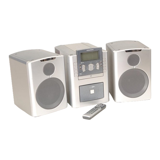
HIFI STEREO MICRO SYSTEM
Service Manual
UMS 100
GLK0752
6
TUNER/BAND
TIMER
MONO/
STEREO
DSC
BASS
BOOST
CD
OPEN/
CLOSE
Grundig Service
Technik:
TV
TV
SAT
VCR/LiveCam
HiFi/Audio
Car Audio
Telekommunikation
Planatron
Ersatzteil-Verkauf:
Hotline Deutschland...
...Mo.-Fr. 8.00-18.00 Uhr
0180/52318-41
0180/52318-49
0180/52318-48
0180/52318-42
0180/52318-43
0180/52318-44
0180/52318-45
Fax:
0180/52318-51
0180/52318-99
(8.00-22.00 Uhr)
...Mo.-Fr. 8.00-19.00 Uhr
Telefon:
0180/52318-40
Fax:
0180/52318-50
Advertisement
Table of Contents

Related Manuals for Grundig UMS-100


Summary of Contents for Grundig UMS-100
-
Page 1: Grundig Service
REV MODE BASS RANDOM BOOST INTRO REC/ CD COPY OPEN/ CLOSE HIFI STEREO MICRO SYSTEM Grundig Service Hotline Deutschland..Mo.-Fr. 8.00-18.00 Uhr Technik: 0180/52318-41 0180/52318-49 Zusätzlich erforderliche Unterlagen für den Komplettservice 0180/52318-48 Additionally required Service Documents for the Complete Service VCR/LiveCam... -
Page 2: Table Of Contents
Testcassette 3150Hz/10kHz (z.B. 448), Test-CD Digital voltmeter, Test cassette 3150Hz/10kHz (e.g. 448), Test CD Beachten Sie bitte das GRUNDIG Messtechnik-Programm, das Sie Please note the GRUNDIG Catalog "Test and Measuring Equipment" unter folgender Adresse erhalten: obtainable from: GRUNDIG AG; Geschäftsbereich Instruments; Test- und Mess-Systeme Würzburger Str. -
Page 3: Technische Daten
Abmessungen Lautsprecher ....B x H x T 200 x 280 x 260mm Weight of device ............... 4.5kg Dimensions of speakers ....W x H x L 200 x 280 x 260mm Gewicht pro Lautsprecher ............3,2kg Weight per speaker ..............3.2kg GRUNDIG Service 1 - 3... -
Page 4: Bedienhinweise
Allgemeiner Teil / General Section UMS 100 Bedienhinweise Dieses Kapitel enthält Auszüge aus der Bedienungsanleitung. Weitergehende Informationen entnehmen Sie bitte der gerätespezifischen Bedienungsanleitung, deren Materialnummer Sie in der entsprechenden Ersatzteilliste finden. 1 - 4 GRUNDIG Service... - Page 5 UMS 100 Allgemeiner Teil / General Section GRUNDIG Service 1 - 5...
-
Page 6: Operating Hints
UMS 100 Operating Hints This chapter contains excerpts from the operating instructions. For further particulars please refer to the appropriate user instructions the part number of which is indicated in the relevant spare parts list. 1 - 6 GRUNDIG Service... - Page 7 UMS 100 Allgemeiner Teil / General Section GRUNDIG Service 1 - 7...
- Page 8 Allgemeiner Teil / General Section UMS 100 1 - 8 GRUNDIG Service...
-
Page 9: Ausbauhinweise
- Undo 2 screws F (Fig. 6) and remove the holder. - 2 Schrauben F (Fig. 6) herausdrehen und den Halter abnehmen. - When necessary unplug connectors. - Bei Bedarf Steckverbindungen lösen. Fig. 1 Fig. 2 Fig. 3 Fig. 5 Fig. 4 Fig. 6 GRUNDIG Service 1 - 9... - Page 10 - 2 Schrauben K (Fig. 10) herausdrehen. - Undo 2 screws K (Fig. 10). - Rastnase L (Fig. 10) ausrasten. - Disengage hook L (Fig. 10). - Bei Bedarf Steckverbindungen lösen. - When necessary unplug connectors. Fig. 9 Fig. 10 1 - 10 GRUNDIG Service...
-
Page 11: General Section ............................ 1 - 2
Cassettentürhalter • die in Fig. 14 (Fig. 13) is fitted correct and the cassette door holder • is in the gezeigte Position hat. position shown in Fig. 14. Fig. 11 Fig. 12 • Fig. 13 Fig. 14 GRUNDIG Service 1 - 11... -
Page 12: Abgleichvorschriften
Eingang (alternativ: Rundfunksender). Digital-Voltmeter zwischen Messpunkte D und E. Mit T107 g (linker Kanal) und mit T108 f (rechter 5. 19kHz-Sperrkreise Mess-Sender an FM-Antennen-Eingang; Kanal) auf NF-Minimum abgleichen. Ue = 50dBµV; f = 19kHz; Oszilloskop an Lautsprecher-Ausgänge. 2 - 1 GRUNDIG Service... -
Page 13: Cassette
Bei “TAPE <“ mit Kopfschraube n auf maximalen und gleichen Pegel auf beiden Kanälen abgleichen. 4. Band- Frequenzzähler an Lautsprecher-Ausgang. Mit dem Einstellregler (im Cass.-Motor) ± Geschwindigkeit Test-Cassette einlegen und 3,15kHz-Teil abspielen. auf 3,15kHz 0,1% einstellen. Bandgeschwindigkeit Tape Speed GRUNDIG Service 2 - 2... - Page 14 Taste T drücken und gedrückt halten. Digital-Voltmeter an Messpunkte J und I (GND). 3. Tracking Offset CD STOP. ± Mit VR3 u auf 0V VR4 r auf Mittelstellung. 100mV abgleichen. ± Mit VR4 r auf 0V 5mV abgleichen. 2 - 3 GRUNDIG Service...
-
Page 15: Adjustment Procedures
Digital Voltmeter between Testpoints D and E. Adjust with T107 g (left channel) and with T108 f (right 5. 19kHz Filter Signal Generator to FM Aerial Input; channel) for AF Minimum. Ue = 50dBµV; f = 19kHz; Oscilloscope to Loudspreaker Outputs. GRUNDIG Service 2 - 4... -
Page 16: Cassette
4. Tape Speed Frequency Counter to Loudspreaker Output. With adjustment control (in the cassette motor) set the ± Insert Test Cassette and play 3.15kHz part. frequency to 3.15kHz 0.1%. Bandgeschwindigkeit Tape Speed 2 - 5 GRUNDIG Service... - Page 17 Press and hold depressed the button T. Digital Voltmeter to Testpoints J and I (GND). 3. Tracking Offset CD STOP. ± With VR3 u adjust for 0V Set VR4 to Center Position. 100mV. ± With VR4 r adjust for 0V 5mV. GRUNDIG Service 2 - 6...
-
Page 18: Layout Of Pcbs And Circuit Diagrams
CN901 RECTIFIER PCB M201-01-06 CASSETTE.PCB AGND TAPE_R_OUT AGND M201-01-03 TAPE_L_OUT TAPE_REC_R_IN AGND TAPE_REC_L_IN CN301 HS301 R/P HEAD REC/PL PLAY-M REC-M CHGND CN302 12VM R-REC CASSETTE DECK PC MTR+ PL-SW SENSOR SOL_A_(PLUNGER) PACK F-REC BEAT CN304 3 - 1 GRUNDIG Service... -
Page 19: Mains Unit
Page 3-5 IC 901 - BA09ST Termal Fuse 125¡C IC 902 - NJM78M56FA zu CON8 Hauptplatte Schaltplanteil Tuner Seite 3-6 to CON8 Main PCB Circuitdiagram Netz/Mains Tuner 230V~ Page 3-6 GRUNDIG Service 3 - 2 GRUNDIG Service 3 - 3... -
Page 20: Main Pcb - Circuit Diagram Af / Amplifier
Schaltplanteil Circuitdiagram Tuner Tuner Seite 3-6 Page 3-6 zu CN301 zu CN901 to CN901 Cassettenteil Netzteil Mains Unit Seite 3-16 Seite 3-2 Page 3-2 to CN301 Tape PCB Page 3-16 3 - 4 GRUNDIG Service 3 - 5 GRUNDIG Service... -
Page 21: Main Pcb - Circuit Diagram Tuner Part
FFC201 Bedienplatte Block Diagram S./P. 3-10 Seite 3-13 Block Diagram to FFC201 S./P. 3-10 Operating PCB Page 3-13 Seite/Page zu CON2 Schaltplanteil Seite 3-8 to CON2 Circuitdiagram Page 3-8 GRUNDIG Service 3 - 6 GRUNDIG Service 3 - 7... -
Page 22: Main Pcb - Circuit Diagram Cd Part
FFC202 Operating PCB Page 3-13 zu CN304 Cassettenteil Seite 3-16 to CN304 Tape PCB Page 3-16 Seite/Page TA7291S zu CON1 to CON1 Schaltplanteil Circuitdiagram Tuner Tuner Seite 3-6 Page 3-6 3 - 8 GRUNDIG Service 3 - 9 GRUNDIG Service... -
Page 23: Main Pcb (Tuner, Af / Amplifier, Cd)
Für die tatsächliche Bestückung ist der Schaltplan maßgebend! The circuit diagram is relevant for the actual component assembly! Main PCB IC 102 - TC9257P IC 103 - BU1923 FE 101 GRUNDIG Service 3 - 10 GRUNDIG Service 3 - 11... - Page 24 Bedienplatte / Operating PCB zu FFC204 Hauptplatte Schaltplanteil Tuner Seite 3-6 to FFC204 Main PCB Circuitdiagram Tuner Page 3-6 zu FFC203 Hauptplatte Schaltplanteil Seite 3-8 to FFC203 Main PCB Circuitdiagram Page 3-8 3 - 12 GRUNDIG Service 3 - 13 GRUNDIG Service...
- Page 27 Seite 3-8 to CON304 Main PCB Circuitdiagram Page 3-8 zu CON304 Hauptplatte Schaltplanteil NF / Verstärker Seite 3-4 to CON304 Main PCB Circuitdiagram AF / Amplifier Page 3-4 IC301 - UPC1330HA GRUNDIG Service 3 - 16 GRUNDIG Service 3 - 17...
- Page 28 Explosionszeichnungen und Ersatzteilliste / Exploded Views and Spare Parts List UMS 100 Explosionszeichnungen und Ersatzteilliste / Exploded Views and Spare Parts List UMS 100 Explosionszeichnungen und Ersatzteilliste / Exploded Views and Spare Parts List UMS 100 4 - 1 GRUNDIG Service 4 - 2 GRUNDIG Service...
- Page 29 UMS 100 Explosionszeichnungen und Ersatzteilliste / Exploded Views and Spare Parts List CD-Laufwerk / CD Mechanism Boxen / Boxes GRUNDIG Service 4 - 3...
- Page 30 759550145600 PUFFER CUSHION F 00906 831561700400 SI 5X20 T1A L 250V Q 00113 759550360800 TRANS 3CA8550 0201.000 759550405700 EMBLEM GRUNDIG EMBLEM GRUNDIG F 00907 831561900331 SI 5X20 T1,6A L 250V Q 00115 759550360800 TRANS 3CA8550 0202.000 759550368700 GUMMI FUSS 10X2MM...
- Page 31 POS. NR. MATERIAL-NR. BEZEICHNUNG POS. NR. MATERIAL-NR. BEZEICHNUNG POS. NO. PART NUMBER DESCRIPTION POS. NO. PART NUMBER DESCRIPTION Q 00307 759550360700 TRANS 3DA8050 T 00108 759550362000 FILTER IFTPF012C 10MM Q 00308 759550141700 TRANS SC-072 T 00301 759550401500 FILTER IFT 3A700N Q 00309 759545032200 TRANSISTOR DTC114ES R21...
Need help?
Do you have a question about the UMS-100 and is the answer not in the manual?
Questions and answers