Advertisement
Available languages
Available languages
Service
Zusätzlich erforder-
Manual
liche Unterlagen
für den
Komplettservice:
UMS 1
UMS 2
Additionally
required Service
Sach-Nr./Part No.
Manuals for the
72010-748.20
Complete Service:
UMS 1
UMS 2
IR-Geber / IR Remote Control RC-UMS
Änderungen vorbehalten
Subject to alteration
SERVICE MANUAL
Service
Manual
Sicherheit
Safety
Sach-Nr./Part No.
72010-800.00
38
(9.79401-8151 / G.LF 1251)
(9.79402-8151 / G.LF 1351)
(75954-029.64)
Printed in Germany
VK 231 0196
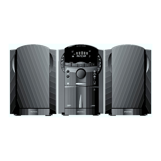
HiFi-Micro-System UMS 1
HiFi-Micro-System UMS 2
3
ANTENA
SLEEP
TUNER
PTY
< STATION >
CD
TAPE
AUX
+
EQUALIZER
VOLUME
R C U M S
Service Manual Sach-Nr.
Service Manual Part No.
72010-748.20
Advertisement
Table of Contents

Related Manuals for Grundig UMS 2


Summary of Contents for Grundig UMS 2
- Page 1 Safety Additionally required Service Sach-Nr./Part No. Sach-Nr./Part No. Manuals for the 72010-748.20 72010-800.00 HiFi-Micro-System UMS 1 Complete Service: HiFi-Micro-System UMS 2 ANTENA SLEEP TUNER < STATION > TAPE EQUALIZER VOLUME R C U M S UMS 1 (9.79401-8151 / G.LF 1251) UMS 2 (9.79402-8151 / G.LF 1351)
-
Page 2: Table Of Contents
Testcassette 448 A part no. 35079-023.00 Drehmomentcassette 456 Sach-Nr. 35079-014.00 Cassette torque meter 456 part no. 35079-014.00 Beachten Sie bitte das GRUNDIG Meßtechnik-Programm, das Sie Please note the Grundig Catalog “Test and Measuring Equipment” unter folgender Adresse erhalten: obtainable from: GRUNDIG electronics GmbH GRUNDIG electronics GmbH Würzburger Str. -
Page 3: Technische Daten
UMS 1 / UMS 2 Allgemeiner Teil / General Section Technische Daten Technical Data Verstärker Amplifier Ausgangsleistung (DIN 45500) Output power (DIN 45500) UMS 1 UMS 1 Musikleistung (4Ω) ............. 2 x 24W Music (4Ω) ..............2 x 24W Sinusleistung (4Ω, 10% Klirrfaktor, f = 1kHz) .... 2 x 15W Nominal (4Ω, 10% dist., f = 1kHz) ...... -
Page 4: Bedienhinweise
TUNER-Betrieb: Mit dieser Taste wird auf der Anzeige zwischen STATION 1 2 – Mit dieser Tasten wählen Sie die Speicherplätze. PHONES Hier können Sie einen handelsüblichen Sendername (RDS, nur UMS 2) (oder einem Stereo-kopfhörer mit 6,3 mm-Klinkenstecker von Ihnen gegebenen Namen), RADIOTEXT anschließen. Die Lautstärke stellen Sie mit und Senderfrequenz hin- und hergeschaltet. - Page 5 • Wählen Sie den Tuner durch Drücken der Taste TUNER. JAZZ: für den metallischen Biß von Jazz-Quartets aus der • Drücken Sie die Tasten 1 STATION 2. RDS Radio Data System (nur UMS 2) Nähe. – Im Display erscheint die ausgewählte Speicherstelle, und CLASSIC: für die dramatische Tiefe klassischer Musik in...
- Page 6 • Drücken Sie die Taste , wechselt die Anzeige zwischen Sendungen mit populären Hits und modernen Schlägern, Eingabesperre. Übertragungen von Bundestags- und Landtagsdebatten o.ä. Stationsnamen RDS (nur UMS 2) oder eigen vergeben), deutsch und international. RDS-Zeit, RADIOTEXT (bei RDS-Sendern, nur UMS 2) ) INFO = Spezielle Wortprogramme ROCK M.
- Page 7 Allgemeines Abspielen einer CD Titelsprung (TRACK NEXT/PREVIOUS) Programm-Betrieb Um die Disc aus ihrem Gehäuse • Drücken Sie die Taste B auf dem Gerät (oder auf dem • Drücken Sie die Taste SKIP T, so wird an den Anfang Jede CD läßt sich in der Reihenfolge der Titel neu gestalten, zu nehmen, fassen Sie sie mit Ferngeber) um die Wiedergabe zu starten.
- Page 8 Cassettendeck Kopieren von CD auf Cassette (CD-COPY) Allgemeines Rauschminderungssystem (DOLBY NR) Programmieren im PLAY-Betrieb Sie können CD´s mit nur einem Tastendruck auf Band Copyright: Aufzeichnungen sind insoweit erlaubt, als dadurch Dolby Rauschunterdrückung ist hergestellt unter Lizenz von Sie können ein Programm auch erstellen, während Sie eine CD überspielen.
- Page 9 Cassettendeck Uhr und Timer Schneller Vor-/Rücklauf einer Cassette Aufnahme Uhreinstellung Timer-Funktion Diese Funktionen sind nur aus STOP heraus möglich. Ihr Gerät ist mit der Funktion ALC (Automatic Level Control), Das Gerät verfügt über eine eingebaute Uhr (24 Stunden). Stellen Sie vor dem Einstellen des Timers sicher, daß die Uhr einer automatischen Aussteuerung ausgestattet.
-
Page 10: Operating Hints
This button is used for switching the Volume is adjusted with the rotary display between the station name (RDS, VOLUME knob. only UMS 2), or another name you assign, The system´s speaker outputs are auto- RADIOTEXT and station frequency. matically switched off when the head-... - Page 11 Memory location 6 is not assigned to a station. CLASSIC: for the dramatic depth of classical music in a RDS Radio Data System (only UMS 2) If you are situated at memory location number 5 and press concert hall.
- Page 12 POP M. = Pop music broadcasts of political and similar events. between RDS station name (only UMS 2) or one you have Programmes with popular and modern hits from home and • If you press CANCEL when the name input mode is...
- Page 13 General information CD playback Skip function (TRACK NEXT/PREVIOUS) Programming To remove a CD from its case, • Press B on the unit (or on the remote control) to start play- • By pressing SKIP T you can skip to the beginning of You can programme your own track sequence for each CD.
- Page 14 Cassette Deck Programming in PLAY mode Copying from a CD to cassette (CD-COPY) General information DOLBY NR noise reduction system You can also enter a programme while a CD is playing. Your system enables you to carry out the CD-COPY function Copyright: Making recordings from a prerecorded sound Dolby noise reduction is manufactured under license from by pressing just one button.
- Page 15 Cassette Deck The Clock and Timer Fast winding during normal operation Recording Setting the clock The timer function These funtions are only possible when in the STOP mode. Your unit is equipped with the function (Automatic Level Your unit has a 24 hour clock. Before setting the timer, ensure that the correct clock time is set.
-
Page 16: Ausbauhinweise
Allgemeiner Teil / General Section UMS 1 / UMS 2 Ausbauhinweise Disassembly Instructions Lage der Leiterplatten Location of the PCBs Tastenplatte links Front Keyboard PCB left Bedienplatte Control PCB Control-CD-Platte Control CD PCB Tastenplatte rechts Keyboard PCB right Tunerplatte Tuner PCB Steckverbindungen lösen... - Page 17 UMS 1 / UMS 2 Allgemeiner Teil / General Section 3. CD-Teil ausbauen 3. Removing the CD Unit - Frontblende abnehmen (Pkt. 2). - Remove the front panel (para 2). - 2 Schrauben e (kurz), 2 Schrauben f (lang) und Schraube g - Undo 2 screws e (short), 2 screws f (long) and screw g herausdrehen (Fig.
- Page 18 Allgemeiner Teil / General Section UMS 1 / UMS 2 6. Audioplatte ausbauen 6. Removing the Audio PCB - Chassis-Seitenteil abnehmen (Pkt. 4). - Remove the chassis side part (para 4). - Control-CD-Platte ausbauen (Pkt. 5). - Remove the control CD PCB (para 5).
- Page 19 UMS 1 / UMS 2 Allgemeiner Teil / General Section Fig. 16 Fig. 17 10. Linke bzw. rechte Tastenplatte ausbauen 10. Removing the Keyboard PCB, left or right - Vorsichtig die aufgeklebte seitliche Blende v mit einem Schrau- - Lift off the glued lateral mask v carefully with a screw driver bendreher abhebeln (Fig.
- Page 20 Allgemeiner Teil / General Section UMS 1 / UMS 2 13. Cassettenlaufwerk ausbauen 13. Removing the Tape Drive Mechanism - Frontblende abnehmen (Pkt. 2). - Remove the front panel (para 2). - 4 Schrauben B herausdrehen (Fig. 20). - Undo 4 Schrauben B (Fig. 20).
- Page 21 UMS 1 / UMS 2 Allgemeiner Teil / General Section Chassis Vorlaufkupplung Forward clutch Magnet Fig. 24 Fig. 25 18. Kupplungen ausbauen 18. Removing the Clutches - Laufwerkplatte ausbauen (Pkt. 16). - Remove the drive mechanism circuit board (para 16).
-
Page 22: Bandlaufprüfung
Allgemeiner Teil / General Section UMS 1 / UMS 2 Bandlaufprüfung Tape Run Test - Cassettenaufwerk ausbauen, siehe Pkt. 13 der Ausbauhinweise. - Remove the cassette drive mechanisms, see para 13 of the - Kopflehre 401 (Sach-Nr. 72008-401.00) auflegen. Achten Sie disassembly Instructions. - Page 23 UMS 1 / UMS 2 Abgleich / Alignment Abgleich 1. Tuner Meßgeräte: Wobbler, Meßsender, Stereocoder, Tongenerator, Oszilloskop, Digitalvoltmeter, NF-Voltmeter, Klirrfaktormeßgerät Hinweis: Das Frontend ist ein komplett abgeglichener Baustein. Nur das ZF-Filter muß dem ZF-Verstärker angeglichen werden (1). Die Abstimmspannungen des Frontends haben folgende Größen: 87,5MHz = typ.
- Page 24 Abgleich / Alignment UMS 1 / UMS 2 Abgleichlageplan Tuner 120-150µH Tunerplatte I I I R124 R118 V I I R123 R119 Tabelle für ZF-Programmierung ZF (MHz) ZF/IF Filter 0 = Brücke geöffnet IF (MHz) Farbe 1 = Brücke geschlossen...
- Page 25 UMS 1 / UMS 2 Abgleich / Alignment 2. Cassettendeck Meßgeräte/Meßmittel: Frequenzzähler, NF-Voltmeter, NF-Generator, Klirranalysator, Tonhöhenschwankungsmesser, Cr-Testcassette 448 A (Sach-Nr. 35079-023.00), Drehmomentcassette 456 (Sach-Nr. 35079-014.00). Abgleich-Lageplan siehe Seite 2-5. Abgleich Vorbereitung Abgleichvorgang ± 1. Bandgeschwin- Frequenzzähler an Meßpunkt L. LINE OUT oder R. LINE Mit dem Einstellregler SVR106 3150Hz 1% einstellen.
- Page 26 Abgleich / Alignment UMS 1 / UMS 2 Abgleich Vorbereitung Abgleichvorgang 9. NF-Kopfstrom NF-Voltmeter an Meßpunkt L. REC (linker Kanal) bzw. R. Mit SVR104 (linker Kanal) und mit SVR204 (rechter Kanal) Grobeinstellung REC (rechter Kanal). an den Meßpunkten L. REC und R. REC 6,0mV einstellen.
- Page 27 UMS 1 / UMS 2 Abgleich / Alignment Abgleichlageplan Cassettendeck L. LINE OUT R156 R256 R. LINE OUT IC104 R. DOLBY L. DOLBY R292 F124 F224 R192 BANDGESCHWINDIGKEIT MPX FILTER TAPE SPEED OPT1 WIEDERGABEPEGEL PLAYBACK LEVEL T123 VORMAGNETISIERUNG BIAS KOPFSTROM...
- Page 28 Abgleich / Alignment UMS 1 / UMS 2 Alignment 1. Tuner Test Equipment: Sweep generator, Test generator, Stereo coder, AF generator, Oscilloscope, Digital voltmeter, AF voltmeter, Distortion meter Note: The frontend is a completely preadjusted module. Only the IF filter must be adjusted to the IF amplifier (1). The values of the tuning voltages are: 87.5MHz = typ.
- Page 29 UMS 1 / UMS 2 Abgleich / Alignment Alignment Scheme Tuner 120-150µH Tuner Board I I I R124 R118 V I I R123 R119 Table for IF-Programming ZF (MHz) ZF/IF Filter 0 = Bridge opened IF (MHz) Colour 1 = Bridge closed...
- Page 30 Abgleich / Alignment UMS 1 / UMS 2 2. Cassette Deck Measuring instruments/equipment: Frequency counter, AF voltmeter, AF generator, distortion analyzer, wow and flutter meter, Cr test cassette 448 A (part no. 35079-023.00), torque test cassette 456 (part no. 35079-014.00).
- Page 31 UMS 1 / UMS 2 Abgleich / Alignment Adjustment Preparations Adjustment Procedure 9. Head current AF-voltmeter to test point L. REC (left channel) or to test With SVR104 (left channel) and with SVR204 (right (coarse) point R. REC (right channel).
- Page 32 Abgleich / Alignment UMS 1 / UMS 2 Alignment Scheme Cassette Deck L. LINE OUT R156 R256 R. LINE OUT IC104 R. DOLBY L. DOLBY R292 F124 F224 R192 BANDGESCHWINDIGKEIT MPX FILTER TAPE SPEED OPT1 WIEDERGABEPEGEL PLAYBACK LEVEL T123 VORMAGNETISIERUNG...
- Page 33 UMS 1 / UMS 2 Schaltpläne und Platinenabbildungen / Circuit Diagrams and Layout of PCBs UMS 1 / UMS 2 Schaltpläne und Platinenabbildungen / Circuit Diagrams and Layout of PCBs Schaltpläne und Platinenabbildungen Audioplatte Audio PCB Cassettenplatte Circuit Diagrams and Layout of PCBs...
- Page 34 Schaltpläne und Platinenabbildungen / Circuit Diagrams and Layout of PCBs UMS 1 / UMS 2 Schaltpläne und Platinenabbildungen / Circuit Diagrams and Layout of PCBs UMS 1 / UMS 2 Schaltbild / Circuit Diagram Audio TO CONTROL/CD BOARD TO CONTROL/CD BOARD...
- Page 35 UMS 1 / UMS 2 Schaltpläne und Platinenabbildungen / Circuit Diagrams and Layout of PCBs UMS 1 / UMS 2 Schaltpläne und Platinenabbildungen / Circuit Diagrams and Layout of PCBs Leiterplatten / PCBs Bestückungsseite Component side Kopfhörerplatte / Headphon PCB...
-
Page 36: Bedienteil, Lautstärkeregler
Schaltpläne und Platinenabbildungen / Circuit Diagrams and Layout of PCBs UMS 1 / UMS 2 Schaltpläne und Platinenabbildungen / Circuit Diagrams and Layout of PCBs UMS 1 / UMS 2 Schaltbild / Circuit Diagram Bedienteil, Lautstärkeregler Keyboard Control, Volume Control... - Page 37 UMS 1 / UMS 2 Schaltpläne und Platinenabbildungen / Circuit Diagrams and Layout of PCBs Leiterplatten / PCBs Bestückungsseite Bedienplatte / Keyboard Control PCB Component side DP601 S604 R635 R636 JP603 JP610 JP608 R605 R604 R602 R603 JP609 R606 JP605...
-
Page 38: Tuner
Schaltpläne und Platinenabbildungen / Circuit Diagrams and Layout of PCBs UMS 1 / UMS 2 Tunerplatte / Tuner PCB Bestückungsseite Component side BR0 BR1 BR2 C113 BR111 BR110 C112 C114 R119 R123 BR102 BR103 BR149 BR114 BR116 BR115 R132 C108... - Page 39 UMS 1 / UMS 2 Schaltpläne und Platinenabbildungen / Circuit Diagrams and Layout of PCBs UMS 1 / UMS 2 Schaltpläne und Platinenabbildungen / Circuit Diagrams and Layout of PCBs Schaltplan / Circuit Diagram Tuner 440.0061.00 2SC2714 IFOUT 100R +12V 0...5P...
- Page 40 Schaltpläne und Platinenabbildungen / Circuit Diagrams and Layout of PCBs UMS 1 / UMS 2 Schaltpläne und Platinenabbildungen / Circuit Diagrams and Layout of PCBs UMS 1 / UMS 2 Schaltplan / Circuit Diagram Control, CD CONTROL R651 TO AUDIO BD...
- Page 41 UMS 1 / UMS 2 Schaltpläne und Platinenabbildungen / Circuit Diagrams and Layout of PCBs UMS 1 / UMS 2 Schaltpläne und Platinenabbildungen / Circuit Diagrams and Layout of PCBs TO AUDIO BD TC506 PAGE 3-3 R235 CN506 +12V +5VUP MOTOR DRV.
- Page 42 Schaltpläne und Platinenabbildungen / Circuit Diagrams and Layout of PCBs UMS 1 / UMS 2 Schaltpläne und Platinenabbildungen / Circuit Diagrams and Layout of PCBs UMS 1 / UMS 2 Control-CD-Platte / Control CD PCB Bestückungsseite Component side JP148 C165...
-
Page 43: Cd-Laufwerk
UMS 1 / UMS 2 Schaltpläne und Platinenabbildungen / Circuit Diagrams and Layout of PCBs UMS 1 / UMS 2 Schaltpläne und Platinenabbildungen / Circuit Diagrams and Layout of PCBs CD-Laufwerk Schaltplan / Circuit Diagram CD Drive Mechanism Cassette C109... - Page 44 Schaltpläne und Platinenabbildungen / Circuit Diagrams and Layout of PCBs UMS 1 / UMS 2 Schaltpläne und Platinenabbildungen / Circuit Diagrams and Layout of PCBs UMS 1 / UMS 2 MECH. DECK (R/P) +12V PLAYBACK CRF 4134 LEVEL L DOLBY NOISE...
- Page 45 UMS 1 / UMS 2 Schaltpläne und Platinenabbildungen / Circuit Diagrams and Layout of PCBs UMS 1 / UMS 2 Schaltpläne und Platinenabbildungen / Circuit Diagrams and Layout of PCBs Cassettenplatte / Cassette PCB Laufwerk-Verdrahtung Bestückungsseite Drive Mechanism Wiring Component side...
- Page 46 Schaltpläne und Platinenabbildungen / Circuit Diagrams and Layout of PCBs UMS 1 / UMS 2 Schaltpläne und Platinenabbildungen / Circuit Diagrams and Layout of PCBs UMS 1 / UMS 2 IC Blockdiagramme IC X 24 COOP IC TDA 1311 IC LM 833, NJM 4556...
- Page 47 UMS 1 / UMS 2 Explosionszeichnungen und Ersatzteillisten / Exploded Views and Spare Parts Lists UMS 1 / UMS 2 Explosionszeichnungen und Ersatzteillisten / Exploded Views and Spare Parts Lists Explosionszeichnungen und Ersatzteillisten Ersatzteilliste Exploded Views and Spare Parts Lists...
- Page 48 Explosionszeichnungen und Ersatzteillisten / Exploded Views and Spare Parts Lists UMS 1 / UMS 2 Explosionszeichnungen und Ersatzteillisten / Exploded Views and Spare Parts Lists UMS 1 / UMS 2 Explosionszeichnung Exploded View UMS 1 / UMS 2 4 - 3...
- Page 49 0037.000 75954-029.44 KNOPF BETRIEBSART OBEN KNOB MODE UPPER 0038.000 75952-042.08 ZAHNRAD, CASSETTENDECKEL GEAR WHEEL, CASS.LID 0040.000 75954-029.45 FEDER SPRING 0041.000 75952-055.04 GRUNDIG LOGO GRUNDIG EMBLEM 0042.000 59852-004.00 DRUCKSCHNAEPPER PRESSURE SNAPPER 0043.000 75954-029.46 CASSETTE TUER CASSETTE DOOR 0046.000 75954-029.48 ABDECKUNG COVER 0047.000...
- Page 50 IC TA 8135P DIP 16 D 606 75952-030.43 SI-DIODE 1 N 4148 D 607 75954-029.11 DIODE LED GREEN RLL3N4GD- D 608 75954-029.11 DIODE LED GREEN RLL3N4GD- L 102 75954-015.22 SPULE 10MH +-10% ÄNDERUNGEN VORBEHALTEN ALTERATIONS RESERVED 4 - 6 GRUNDIG Service...
-
Page 51: Tuner
Service Manual "Sicherheit", valid as provided by the "Safety" Service Manual, Sach-Nummer 72010-800.00, sowie zusätzlich part number 72010-800.00, as well as the die eventuell abweichenden, landesspezifischen respective national deviations. Vorschriften! ÄNDERUNGEN VORBEHALTEN ALTERATIONS RESERVED GRUNDIG Service 4 - 7... - Page 52 Ersatzteilliste / Spare Parts List UMS 2 Ersatzteilliste Spare Parts List 32700 # 12 / 95 UMS 2 SACH-NR. / PART NO.: 9.79402-8151 BESTELL-NR. / ORDER NO.: G.LF 1351 POS. ABB. SACHNUMMER ANZ. DESCRIPTION BEZEICHNUNG POS. NO. FIG. PART NUMBER QUA.
- Page 53 UMS 2 Ersatzteilliste / Spare Parts List POS. SACHNUMMER BEZEICHNUNG POS. SACHNUMMER BEZEICHNUNG POS. PART NUMBER DESCRIPTION POS. PART NUMBER DESCRIPTION CD PLATTE D 609 75954-029.11 DIODE LED GREEN RLL3N4GD- D 610 75954-029.11 DIODE LED GREEN RLL3N4GD- CR 601 75954-029.01 QUARZ KERAMIK CST6,00 MHZ 75954-029.13...
- Page 54 Ersatzteilliste / Spare Parts List UMS 2 POS. SACHNUMMER BEZEICHNUNG POS. SACHNUMMER BEZEICHNUNG POS. PART NUMBER DESCRIPTION POS. PART NUMBER DESCRIPTION 75954-010.14 TRIMMER 4,5/20 PF L 202 75954-015.22 SPULE 10MH +-10% 75954-010.14 TRIMMER 4,5/20 PF L 401 75954-010.66 OSZ.SPULE 75954-010.18...
Need help?
Do you have a question about the UMS 2 and is the answer not in the manual?
Questions and answers