Table of Contents
Advertisement
Advertisement
Table of Contents

Subscribe to Our Youtube Channel
Related Manuals for Grundig GCI-K1503B


Summary of Contents for Grundig GCI-K1503B
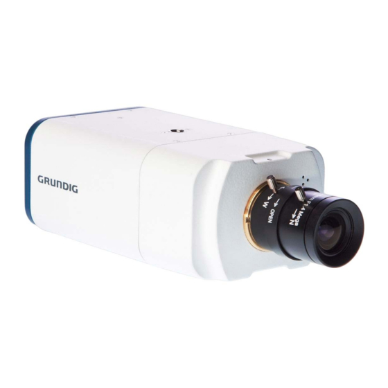
- Page 1 Owner's Manual IP Cameras & Domes GCI-K1503B 2 Megapixel Full HD CMOS Box IP Camera ICR GCI-K1603B 2 Megapixel Full HD CMOS Box IP Camera Soft D/N GCI-F0505B 3 Megapixel Full HD CMOS Box IP Camera ICR WDR GCI-G0509B 5 Megapixel Full HD CMOS Box IP Camera ICR WDR GCI-K1503B.64.1.29.08.2012...
-
Page 3: Table Of Contents
12. Storage Management (on Camera) 16. GRUNDIG Viewer Download Procedure 13. Recording (on Camera) 17. Install UPnP Components 14. File Location (on PC) 18. Deleting the Existing GRUNDIG Viewer 15. Iris Adjustment 19. Back Focus Adjustment 16. View Log File 17. View User Information 18. -
Page 4: Introduction
1. Introduction Supported with both H.264 and MJPEG standard, this GRUNDIG camera series not only features a superior Full HD resolution for streaming at 25 fps, but also supplies a D1 720p streaming. With more computing power, these IP Cameras can provide more flexibility for users and system managers. -
Page 5: Camera Overview
4.1. Camera Overview 4.2. System Requirements To perform the IP Camera via web browser, please ensure your PC is in good network connection, and meets the system requirements as described below. Personal Computer : 1.) Intel Pentium M, 2.16 GHz or Intel Core 2 Duo, 2.0 GHz 2.) 2 GB RAM or more Operating System : Windows XP / Windows VISTA / Windows 7... -
Page 6: Lens Mounting
Mount lens, you need a 5 mm C/CS Mount Adapter between the camera and the C-Mount lens, as shown in the illustration below. 4.4. Power Connection Power Connection for GCI-K1503B and GCI-G0509B: Please refer to section 4.1. Camera Overview for power wiring. Additionally, if using PoE, make sure Power Sourcing Equipment (PSE) is in use in the network. -
Page 7: Alarm Application
Finder.exe, which can be found on the supplied CD. GRUNDIG Finder Software Setup : Step 1: Double-click on the program GRUNDIG Finder.exe (see the desktop icon below). Its window will appear as shown below. Then click on the “Find Device” button. - Page 8 Device Search : Step 3: Click “Find Device” again, afterwards all IP devices found will be listed on the page, as shown in the picture below. The IP Camera’s default IP address is: 192.168.1.1. Step 4: Double-click or right-click and select “Browse” to access the camera directly via the web browser. Step 5: Then the dialogue box for entering the default user name and password (as shown below) will appear for login to the IP Dome Camera.
- Page 9 NOTE: ID and password are case sensitive. It is strongly advised to alter the administrator’s password due to security concerns. Please refer to section 9.2. Security for further details. Additionally, users can change the IP Camera’s network property, either to DHCP or Static IP, directly in the device finding list.
- Page 10 16. GRUNDIG Viewer Download Procedure. NOTE: If the Live Video Pane on the Home Page cannot be shown to the users who have installed the GRUNDIG Viewer on the PC previously, please refer to the procedure in chapter 18. Delete the Existing GRUNDIG Viewer.
- Page 11 Once logged in to the IP Camera, users will see the Home page as shown below: Administrator/User Privileges : “Administrator” represents the person who can configure the IP Camera and who authorises users to have access to the camera; “User” refers to someone who has access to the camera with limited authority, i.e. to enter the Home and Camera setting pages.
-
Page 12: Video Resolution Setup
The users can set up the Video Resolution on the Video Format page of the user-friendly browser-based configuration interface. The page “Video Format” can be found in the IP camera menu under the path: Streaming > Video Format. For the camera model GCI-K1503B the resolution options are: English... - Page 13 English...
- Page 14 For more streaming combinations with several streams, please refer to "Streaming" > "Video Format" in the camera menu. English...
- Page 15 For the camera model GCI-K1603B the resolution options are different. For this camera the following options are available: English...
- Page 16 English...
- Page 17 For more streaming combinations with several streams, please refer to "Streaming" > "Video Format" in the camera menu. English...
- Page 18 For the camera model GCI-F0505B the resolution options are different. For this camera the following options are available: English...
- Page 19 English...
- Page 20 For more streaming combinations with several streams, please refer to "Streaming" > "Video Format" in the camera menu. English...
- Page 21 For the camera model GCI-G0509B the resolution options are different. For this camera the following options are available: English...
- Page 22 English...
- Page 23 For more streaming combinations with several streams, please refer to "Streaming" > "Video Format" in the camera menu. English...
-
Page 24: Browser-Based Viewer Introduction
Users can adjust various camera parameters. Further details will be interpreted in chapter 11. Camera Settings. Pan/Tilt : This menu is only available in the models GCI-K1503B and GCI-G0509B with RS-485 Interface. The users can adjust here various PTZ parameters. -
Page 25: Home Page
8. Home Page In the Home page, there are several function buttons that are specified below. Display Mode (Screen Size Adjustment) : The display size of the image can be adjusted to x1/2 and full screen. Talk button (on/off) : Talk function allows the local site to talk to the remote site. - Page 26 NOTE: The following functions are not available for the Browsers Firefox, Chrome, Safari and Opera: Full Screen Mode, Audio talk/listen, Snapshot, Playback and Recording. The following functions are additional in the camera models GCI-K1503B and GCI-G0509B with RS- 485 Interface: Pan/Tilt : Here you find the settings for the Pan/Tilt function.
- Page 27 Focus Adjustment : Users can adjust the focus manually via the "Near" and "Far" buttons. Iris Adjustment : Please choose <Open> to open the iris and <Close> to close the iris. English...
-
Page 28: System Related Settings
9. System Related Settings The picture below shows all categories under the “System” tab. Each category in the left column will be explained in the following sections. NOTE: The “System” configuration page is only accessible by the Administrator. 9.1. Host Name & System Time Setting Click on the first category <System>... -
Page 29: Security
Host Name : The name is for camera identification (max. 30 characters). If the alarm function (see section 9.8. 'Application (Alarm Settings)') is enabled and is set to send an alarm message by Mail/FTP, the host name entered here will be displayed in the alarm message. - Page 30 Admin Password : Change the administrator’s password by putting in the new password in both text boxes. The input characters/numbers will be displayed as dots for security purposes. After clicking <Save>, the web browser will ask the Administrator for the new password for access. The maximum length of the password is 14 digits. NOTE: The following characters are valid: A-Z, a-z, 0-9, !#$%&’-.@^_~.
- Page 31 <HTTPS> : <HTTPS> allows secure connections between the IP Camera and the web browser using the <Secure Socket Layer (SSL)> or the <Transport Layer Security (TLS)>, which prevent others from snooping on your camera settings or Username/Password. It is required to install a self-signed certificate or a CA-signed certificate for implemention of <HTTPS>.
- Page 32 Create self-signed certificate : Before a CA-issued certificate is obtained, users can create and install a self-signed certificate first. Click on the <Create> button under “Create self-signed certificate” and provide the requested information to install a self-signed certificate for the IP Camera. Please refer to the last part of this section: "Provide the Certificate Information"...
- Page 33 Install signed certificate : Click on the “Create Certificate Request” button to create and submit a certificate request in order to obtain a signed certificate from the CA (Certificate Authority). Provide the requested information in the Create Dialog. Please refer to the section "Provide the Certificate Information"...
- Page 34 When the signed certificate is returned, install it by uploading the signed certificate. Provide the Certificate Information : To create a Self-signed HTTPS Certificate or a Certificate Request to CA, please enter the information as requested: English...
- Page 35 - Country: Enter a 2-letter combination code to indicate the country the certificate will be used in. For instance, type in “GB” to indicate Great Britain. - State or province: Enter the local administrative region. - Locality: Enter other geographical information. - Organisation: Enter the name of the organisation to which the entity identified in “Common Name”...
- Page 36 <IP Filter> : When using the IP filter, access to the IP Camera can be restricted by denying/allowing specific IP addresses. General : - Enable IP Filter: Check the box to enable the IP Filter function. Once enabled, access to the IP Camera will be allowed/denied for the listed IP addresses (IPv4).
- Page 37 <IEEE 802.1X> : The IP Camera can access a network protected by 802.1X/EAPOL (Extensible Authentication Protocol over LAN). To do this, users need to contact the network administrator to receive certificates, user IDs and passwords. CA Certificate : The CA certificate is created by the Certification Authority for the purpose of validating itself. Upload the certificate for checking the server’s identity.
-
Page 38: Network
9.3. Network When you click on the category <Network>, there will be a drop-down menu with several tabs including <Basic>, <QoS>, <SNMP>, and <UPnP>. <Basic> : Users can choose to connect to the IP Camera through a fixed or dynamic (DHCP) IP address. The IP Camera also provides PPPoE (Point-to-Point Protocol over Ethernet) support for users who connect to the network via PPPoE. - Page 39 192.168.44.1. Click on “Save” to confirm the new setting. When using a static IP address to login to the IP Camera, users can access it either through the “GRUNDIG Finder” software (see 6. Accessing the Camera) or input the IP address in the URL bar and click on “Enter”.
- Page 40 - Secondary DNS: Secondary DNS is a secondary domain name server that backs up the primary DNS. Use PPPoE : The PPPoE users need to enter the PPPoE Username and Password into the fields, and need to click on the “Save”...
- Page 41 DSCP Settings : The DSCP value range is from 0 to 63. The default DSCP value is 0, which means that DSCP is disabled. The IP Camera uses the following QoS Classes: Video, Audio and Management. - Video DSCP: This class consists of applications such as MJPEG over HTTP, RTP/RTSP and RTSP/HTTP. - Audio DSCP: This setting is only available for the IP Cameras which support audio.
- Page 42 Traps for SNMP v1/v2 : Traps are used by the IP Camera to send messages to a management system about important events or status changes. - Enable Traps: Check the box to activate trap reporting. - Trap address: Enter the IP address of the management server. - Trap community: Enter the community to use when sending a trap message to the management system.
- Page 43 UPnP Setting : - Enable UPnP: When UPnP is enabled, whenever the IP Camera is presented to LAN, the icon of the connected IP Cameras will appear in My Network Places to allow for direct access as shown below. NOTE: To enable this function, please make sure the UPnP component is installed on your computer. Please refer to chapter 17.
-
Page 44: Ddns
9.4. DDNS The Dynamic Domain Name System (DDNS) allows a host name to be constantly synchronised with a dynamic IP address. In other words, it allows those using a dynamic IP address to be associated to a static domain name so that others can connect to it through this name. -
Page 45: Mail
9.5. Mail The Administrator can can set up the sending of an e-mail via Simple Mail Transfer Protocol (SMTP) when a motion is detected. SMTP is a protocol for sending e-mail messages from server to server. SMTP is a relatively simple, text-based protocol, where one or more recipients of a message are specified and to whom the message text is transferred. -
Page 46: Ftp
9.6. FTP The Administrator can set the sending of alarm messages to a specific File Transfer Protocol (FTP) site when motion is detected. Users can assign an alarm message to up to two FTP sites. The FTP setting page is shown below. -
Page 47: Http
9.7. HTTP A HTTP Notification server can listen for notification messages from IP Cameras by triggered events. The HTTP setting page is shown below. Enter the HTTP details, which include the server name (for instance, http://192.168.1.1/admin.php), user name, and password into the fields. <Alarm> triggered and <Motion Detection>... -
Page 48: Application (Alarm Settings)
The alarm configuration page is also shown below. PIN 1: Output+ PIN 2: Output- PIN 3: Input+ PIN 4: Input- Additional for GCI-K1503B and GCI-G0509B with RS-485 Interface: PIN 5: GND PIN 6: D- PIN 7: D+ Alarm Switch : The Administrator can enable or disable the alarm function. - Page 49 Triggered Action (Multi-option) : The Administrator can specify alarm actions that will take place when the alarm is triggered. All options are listed as follows: - Enable Alarm Output: Select this item to enable alarm relay output. - IR Cut Filter: If you select this item, the camera’s IR cut filter (ICR) will be removed (on) or blocked (off) when the alarm input is triggered.
- Page 50 The <Pre-trigger buffer> recording function allows users to check what happened to trigger the alarm. The pre- trigger buffer time range is from 1 to 20 frames. On the other hand, the <Post-trigger buffer> is for uploading a certain amount of images after the alarm input is triggered.
- Page 51 The <Pre-trigger buffer> recording function allows users to check what happened to trigger the alarm. The pre- trigger buffer time range is from 1 to 20 frames. On the other hand, the <Post-trigger buffer> is for uploading a certain amount of images after the alarm input is triggered.
- Page 52 - Record Stream to SD Card: After selecting this item, the alarm-triggered recording will be saved on your Micro SD card. The pre-trigger buffer recording function allows users to check what happened to trigger the alarm. The pre- trigger buffer time range is from 1 to 3 seconds. Select <Upload for __ sec>...
-
Page 53: Motion Detection
Save : After completing all the settings mentioned above, please click on the Save button to save all the settings in this page. 9.9. Motion Detection The Motion Detection function allows detecting suspicious motion and triggers alarms when motion volume in the detected area reaches/exceeds the determined sensitivity threshold value. - Page 54 When a motion is detected, the signals will be displayed in the Motion window as shown below: The detailed settings of Motion Detection are described as follows: Motion Detection : You will be able to turn the Motion Detection on/off in the System section "Motion Detection". The default setting is: Off.
- Page 55 - Record Stream to SD Card: When you select this item, the Motion Detection recording will be stored on your Micro SD/SDHC card when motion is detected. The pre-trigger buffer recording function allows users to check what happened to trigger the alarm. The pre- trigger buffer time range is from 1 to 3 seconds.
- Page 56 - Upload Image by E-Mail: After selecting this item, the Administrator can assign an e-mail address and configure various parameters as shown in the picture below. When a motion is detected, event images will be sent to the appointed e-mail address. The <Pre-trigger buffer>...
-
Page 57: Network Failure Detection
9.10. Network Failure Detection This function is used to detect network failure that might happen during camera operation. Detection Switch : Here you can turn the Network Failure Detection on and off. Detection Type : Here you can set an IP address that should be pinged in order to detect network failure. Please also set the interval (in minutes) for this pinging. -
Page 58: Tampering
NOTE: Please make sure that the local recording (with Micro SD/ SDHC card) is activated so that this function can be implemented. See section 9.13. 'Recording (on Camera)' for further details. - Send Alarm Message by FTP: The Administrator can select whether to send an alarm message by FTP when Network Failure is detected. - Send Alarm Message by E-Mail: The Administrator can choose to send an alarm message by E-Mail when Network Failure is detected. - Page 59 - Enable Alarm Output: Check this item and select the predefined type of alarm output to enable alarm relay output when tampering is detected. - Record Stream to SD Card: When you check this item, the alarm-triggered recording will be stored on your Micro SD/SDHC card when tampering is detected.
-
Page 60: Storage Management (On Camera)
- Upload Image by E-Mail: After selecting this item, the Administrator can assign an e-mail address and configure various parameters as shown in the figure below. When tampering is detected, event images will be sent to the appointed e-mail address. The <Pre-trigger buffer>... - Page 61 NOTE: Please format the Micro SD/SDHC card when using it for the first time. Formatting will also be required when a memory card has already been used on one device and was later transferred to another device with a different software platform. Device Information : When users insert the Micro SD/SDHC card, the card information such as the memory capacity and status will be shown in the Device Information section.
- Page 62 When the recording mode is set to “Always” (consecutive recording) in the submenu "Recording" and the Micro SD/SDHC card recording is also allowed to be enabled when triggered by events, once the events occur, the system will immediately implement the recorded events to the memory card. After event recording, the device will return to regular recording mode.
-
Page 63: Recording (On Camera)
9.13. Recording (on Camera) In the Recording setting page, users can specify the recording schedule that fits the present surveillance requirement. Activating Micro SD/SDHC Card Recording : Two types of schedule mode are offered: "Always" and "Only during time frame". You can set up the time frame according to your requirements or you can choose “Always”... -
Page 64: File Location (On Pc)
9.14. File Location (on PC) Users can specify a storage location for the snapshots and the live video recording. The default setting is: C:\. Once the setting is confirmed, click on “Save,” and all the snapshots and recordings will be saved in the designated location. -
Page 65: Iris Adjustment
9.15. Iris Adjustment For users who use an auto-iris lens, when it is required to undertake an iris adjustment, please refer to the iris adjustment procedure in the sub-menu "Iris Adjustment" to adjust the iris. 9.16. View Log File Click on the link to view the system log file. The content of this file provides useful information about configuration and connections after system boot-up. -
Page 66: View User Information
9.17. View User Information The Administrator can view each user’s login information and their privileges (see section 9.2. Security). View User Login Information : All the users in the network will be listed in the “User Information” zone, as shown below. The picture below shows: User: 4321 This indicates that one user’s login username is: User, and the password is: 4321 English... - Page 67 View User Privilege : If you click on “Get user privacy” at the bottom of the page, the Administrator will be able to view each user’s privileges. As the picture above shows: User: 1:1:0:1 1:1:0:1 = I/O access : Camera control : Talk : Listen (see 9.2. Security) This denotes that the user has been granted the privileges of I/O access, Camera control and Listen.
-
Page 68: View Parameters
9.18. View Parameters Click on this item to view the entire system’s parameter setting. 9.19. Factory Default The factory default setting page is shown below. Follow the instructions to reset the IP Camera to factory default setting if needed. English... -
Page 69: Software Version
Set Default : Click on the “Set Default” button to recall the factory default settings. After 30 seconds the system will restart. NOTE: The IP address will also be restored to default (192.168.1.1). Reboot : When you click on the “Reboot” button, the system will restart without changing the current settings. 9.20. -
Page 70: Software Upgrade
Step 5: Go to “Start” on your Windows desktop, activate “Control Panel”, and then double-click on ”Add or Remove Programs“. In the “Currently installed programs” list, select “GRUNDIG Viewer” and click on the button “Remove” to uninstall the existing GRUNDIG Viewer. -
Page 71: Maintenance
9.22. Maintenance Users can export configuration files to a specified location and retrieve data by uploading an existing configuration file to the IP Camera. This is especially convenient if you want to have the same configuration for multiple cameras. Export: Users can save the system settings by exporting the configuration file (.bin) to a specified location for future use. -
Page 72: Streaming Settings
10. Streaming Settings 10.1. Video Format Video Resolution : Under the Video Resolution section, the available video resolution formats include MJPEG and H.264. Please refer to Chapter 6. Video Resolution Setup for combination details. Click on “Save” to confirm the setting. Text Overlay Settings : Users can select these items to display data (date/time/text) on the live video pane. - Page 73 To rotate the image, users can select “Flip video”, for instance. Then the displayed image will be reversed as shown below. The following are descriptions of different video rotation types. - Flip video: If you select <Flip video>, the image will be rotated horizontally. - Mirror video: If you select <Mirror video>, the image will be rotated vertically.
-
Page 74: Video Compression
10.2. Video Compression Users can specify the values for MJPEG/H.264 compression mode in the video compression page (see the picture below), depending on the application. MJPEG compression setting (MJPEG Q (Quality) factor): A higher value implies higher bit rates and a higher visual quality. The default setting is 35; the setting range is from 1 to 70. -
Page 75: Video Ocx Protocol
10.3. Video OCX Protocol In the Video OCX protocol setting page, users can select RTP over UDP, RTP over TCP, RTSP over HTTP or MJPEG over HTTP, for streaming media over the network. In the case of multicast networking, users can select the Multicast mode. -
Page 76: Video Frame Rate
10.4. Video Frame Rate Video frame skipping is for saving bandwidth if necessary. The setting page is shown below. MJPEG / H.264-1 / H.264-2 / H.264-3 / H.264-4 Frame Rate: The default setting of MJPEG/H.264-1/H.264-2/H.264-3/H.264-4 Frame Rate is 25 fps. The setting range is from 1 to 25. -
Page 77: Video Mask
10.5. Video Mask There are five video masks which can be set by the users. Active Mask Function : - Add a Mask: When you check a Video Mask checkbox, a red frame will come out in the Live Video pane at the right side. Use the mouse to adjust the mask’s size and drag and drop the frame to place it on the target zone. -
Page 78: Audio (Audio And Bit Rate Settings)
10.6. Audio (Audio and Bit Rate Settings) The audio setting page is shown below. In the Audio page, the Administrator can select one transmission mode and the audio bit rate. Transmission Mode : - Full-duplex (Talk and Listen simultaneously): In the Full-duplex mode, the local and remote sites can communicate with each other simultaneously, i.e. both sites can speak and be heard at the same time. -
Page 79: Camera Settings
11. Camera Settings The picture below is the camera configuration page. Details of each parameter setting are described in the following subsections. 11.1. Exposure Setting Display of the Exposure pull-down menu: The exposure is the amount of light received by the image sensor and is determined by the width of lens diaphragm opening, the amount of exposure by the sensor (shutter speed) and other exposure parameters. -
Page 80: White Balance Setting
- Auto Shutter Mode: This function is used to control the shutter speed and to adjust the iris automatically according to the light intensity. It is also effective if a fixed iris lens is being used. The minimum shutter speed range is configurable from 1/1.5 to 1/425 sec. -
Page 81: Picture Adjustment
11.3. Picture Adjustment Display of the Picture Adjustment pull-down menu: Brightness: The users can adjust the image’s brightness by adjusting the item. Please select a number from the range of -12 to +13. To increase the video brightness, select a bigger number. Click on <... -
Page 82: Ir Function
11.6. IR Function With the IR cut filter, the Camera can still catch a clear image at night time or in low light conditions. NOTE: The IR Function is not available for the camera GCI-K1603B. Auto/On/Off Mode: With the IR cut filter, the Dome Camera can still catch a clear image at night time or in low light conditions. Smart Mode: The Smart Mode enhances the monochrome/night mode stability in ascenario where IR illumination is dominant. -
Page 83: Pan/Tilt
12. Pan/Tilt The camera models GCI-K1503B and GCI-K0509B have a RS-485 Interface. This chapter is referring to the "Pan/Tilt" menu of these specific camera models. With RS-485 support, this IP camera type is capable of working with a Pan Tilt Head for pan and tilt control. -
Page 84: Preset
12.1. Preset Before setting this function, users must enable the Pan/Tilt Control first. Please refer to section 12.3. Pan/Tilt Control for more details. There are up to 127 preset points that can be set in the Preset setup page. Please follow the steps below to set and run the preset points. -
Page 85: Sequence
12.2. Sequence The Sequence function supports in total eight Sequences; each Sequence consists of up to 64 Preset Points. Please refer to the instructions below to program a Sequence. NOTE: Before setting this function, users must pre-define at least two Preset Points. Sequence Setting: - Sequence No.: Please select a number for the Sequence to be set from the drop-down list. -
Page 86: Pan/Tilt Control
12.3. Pan/Tilt Control The users can activate the pan/tilt function here and select the RS-485 protocol that the Pan Tilt Head needs. Pan/Tilt Control: Users can enable or disable the Pan/Tilt Control. Click “Save” to confirm the setting. RS-485 Protocol Type: Protocol and Baud rate type options include: - DSCP (9600) - PelcoD (2400) -
Page 87: Logout
The GRUNDIG CMS Software gives the user access to monitor multiple IP Cameras and Video Servers, and allows the user to monitor simultaneously 16 sites per group (up to 10 groups) within several clicks. -
Page 88: Internet Security Settings
15. Internet Security Settings If the ActiveX control installation is blocked, please either set the Internet security level to default or change ActiveX controls and plug-in settings. Internet Security Level : Default Step 1: Start the Internet Explorer. Step 2: Select <Tools> from the main menu of the browser. Then click on <Internet Options>. Step 3: Click on the <Security>... - Page 89 Step 4: Down the page, click on “Default level…” and then click “OK” to confirm the setting. Close the browser window, and open a new one later when accessing the IP Camera. ActiveX Controls and Plug-in Settings : Step 1~3: Please refer to the previous section above. Step 4: Down the page, click on “Custom level…”...
- Page 90 The Security Settings screen is displayed as shown below: Step 5: Under “ActiveX controls and plug-ins”, set ALL items (as listed below) to <Enable> or <Prompt>. Please note that the items may vary depending on the Internet Explorer version you are using. ActiveX controls and plug-in settings: 1.
-
Page 91: Grundig Viewer Download Procedure
The procedure of the GRUNDIG Viewer software download is specified as follows: Step 1: In the GRUNDIG Viewer installation page, click “Next” to start the installation. Step 2: Setup starts. Please wait for a while until the loading bar runs out. - Page 92 Step 3: Click on “Finish” to close the GRUNDIG Viewer installation page. Then, the IP Camera’s Home page will be displayed as follows: NOTE: Please note that the function buttons may vary depending on the camera model. English...
-
Page 93: Install Upnp Components
17. Install UPnP Components Please follow the instructions below to install UPnP components. (The procedure is for Windows XP, for other systems please refer to the corresponding manuals.) Step 1: Go to “Start”, click on “Control Panel”, and then double-click on “Add or Remove Programs”. Step 2: Click on “Add/Remove Windows Components”... - Page 94 Step 3: Select “Networking Services” from the Components list in the Windows Components Wizard window, and then click on “Details”. Step 4: Select “UPnP User Interface” in the Networking Services’ subcomponents list and then click on “OK”. Step 5: Click on “Next” in the Windows Components Wizard page. English...
-
Page 95: Deleting The Existing Grundig Viewer
Step 6: Click on “Finish” to complete the installation. 18. Deleting the Existing GRUNDIG Viewer Users who have installed the GRUNDIG Viewer for 1.3 Megapixel Series IP Cameras on the PC need to delete the existing GRUNDIG Viewer first from the PC before accessing this IP Camera. - Page 96 STEP 1: Click on the “Tools” tab and select the option “Internet Options”. STEP 2: Click on “Delete” in the first pop-up window. Then tap “Delete Files” in the “Temporary Internet files” section in the next pop-up window. English...
-
Page 97: Back Focus Adjustment
19. Back Focus Adjustment When to adjust the back focus: Back Focus refers to the distance from the rear lens element to the camera focal plane. It is only required to adjust the back focus only when the focus cannot be adjusted throughout its zoom range. Requirements: Tools required when carrying out back focus adjustment include: 1. - Page 98 Specifications GCI-K1503B Image Sensor 1/2.7" CMOS Omnivision, 2 Megapixel Pixels - Total 1920(H) x 1080(V) Col/B&W On/Off/Auto, IR-cut filter removable (ICR) Sensitivity Colour 0.5 Lux@F1.2 (IRE50), 0.2 Lux@F1.2 (IRE30) Sensitivity B&W 0.1 Lux@F1.2 (IRE50), 0.02 Lux@ F1.2 (IRE30) Lens Mount...
- Page 99 Video OUT (BNC), Power (DC Jack), RJ-45, Micro SD Card Slot, Alarm Terminal 4-Pin (Alarm In 2-Pin, Alarm Out 2-Pin), Audio (2 mini Jack 3.5mm) More specifications please see GCI-K1503B, Interfaces/Protocol/PTZ Control: not available Supply Voltage 12 VDC / PoE IEEE 802.3af Power Consumption Weight 0.36 kg...
- Page 100 English...
- Page 101 EC Declaration of Conformity GCI-K1503B 2 Megapixel Full HD CMOS Box IP Camera ICR GCI-K1603B 2 Megapixel Full HD CMOS Box IP Camera Soft D/N GCI-F0505B 3 Megapixel Full HD CMOS Box IP Camera ICR WDR GCI-G0509B 5 Megapixel Full HD CMOS Box IP Camera...
Need help?
Do you have a question about the GCI-K1503B and is the answer not in the manual?
Questions and answers