Table of Contents
Advertisement
ASUS P5SD1-FM2 Manual
http://www.manuallib.com/file/2595652
From ManualLib.com
ManualLib.com collects and classifies the global product
instrunction manuals to help users access anytime and
anywhere, helping users make better use of products.
Home: http://www.manuallib.com/ Chinese: http://www.shuomingshuku.com/
This Manual: http://www.manuallib.com/file/2595652
Advertisement
Table of Contents

Related Manuals for Asus P5SD1-FM2


Summary of Contents for Asus P5SD1-FM2
- Page 1 ASUS P5SD1-FM2 Manual http://www.manuallib.com/file/2595652 From ManualLib.com ManualLib.com collects and classifies the global product instrunction manuals to help users access anytime and anywhere, helping users make better use of products. Home: http://www.manuallib.com/ Chinese: http://www.shuomingshuku.com/ This Manual: http://www.manuallib.com/file/2595652...
- Page 2 P5SD1-FM2 This Manual: http://www.manuallib.com/file/2595652...
- Page 3 Product warranty or service will not be extended if: (1) the product is repaired, modified or altered, unless such repair, modification of alteration is authorized in writing by ASUS; or (2) the serial number of the product is defaced or missing.
-
Page 4: Table Of Contents
Contents Notices ......................vi Safety information ..................vii P5SD1-FM2 specifications summary ............. viii Chapter 1: Hardware information 1 . 1 Before you proceed ..............1 - 2 1 . 2 Motherboard overview ............... 1 - 3 1.2.1 Placement direction ............ 1 - 3 1.2.2... - Page 5 ASUS EZ Flash utility ........... 2 - 3 2.1.3 AFUDOS utility ............. 2 - 4 2.1.4 ASUS CrashFree BIOS 2 utility ........2 - 6 2 . 2 BIOS setup program ..............2 - 1 0 2.2.3 Navigation keys ............2 - 1 1 2.2.1...
- Page 6 Contents 2 . 5 Power menu ................2 - 2 6 2.5.1 ACPI Aware O/S ............2 - 2 6 2.5.2 Suspend Mode ............2 - 2 6 2.5.3 Repost Video on S3 Resume ........2 - 2 6 2.5.4 ACPI 2.0 Support ............
-
Page 7: Notices
Notices Federal Communications Commission Statement This device complies with Part 15 of the FCC Rules. Operation is subject to the following two conditions: • This device may not cause harmful interference, and • This device must accept any interference received including interference that may cause undesired operation. -
Page 8: Safety Information
Safety information Electrical safety • To prevent electrical shock hazard, disconnect the power cable from the electrical outlet before relocating the system. • When adding or removing devices to or from the system, ensure that the power cables for the devices are unplugged before the signal cables are connected. -
Page 9: P5Sd1-Fm2 Specifications Summary
P5SD1-FM2 specifications summary ® ® LGA775 socket for Intel Pentium 4/Celeron processor ® Compatible with Intel Performance Universal FMB ® Supports Intel Hyper-Threading Technology C h i p s e t Northbridge: SiS 649 Southbridge: SiS 965 Front Side Bus... - Page 10 P5SD1-FM2 specifications summary I n t e r n a l 1 x Floppy disk drive connector 1 x Power LED connector c o n n e c t o r s 2 x IDE connectors 4 x Serial ATA connectors...
- Page 11 This Manual: http://www.manuallib.com/file/2595652...
-
Page 12: Chapter 1: Hardware Information
This chapter lists the hardware setup procedures that you have to perform when installing system components. It includes description of the jumpers and connectors on the motherboard. Hardware information This Manual: http://www.manuallib.com/file/2595652... -
Page 13: Before You Proceed
Before you proceed Take note of the following precautions before you install motherboard components or change any motherboard settings. • Unplug the power cord from the wall socket before touching any component. • Use a grounded wrist strap or touch a safely grounded object or a metal object, such as the power supply case, before handling components to avoid damaging them due to static electricity •... -
Page 14: Motherboard Overview
Place six (6) screws into the holes indicated by circles to secure the motherboard to the chassis. Do not overtighten the screws! Doing so can damage the motherboard. Place this side towards the rear of the chassis ASUS P5SD1-FM2 This Manual: http://www.manuallib.com/file/2595652... -
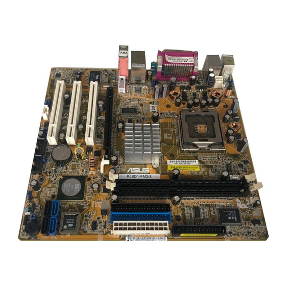
Page 15: Motherboard Layout
1 . 2 . 3 Motherboard layout PS/2KBMS KBPWR CHA_FAN T: Mouse B: Keyboard ATX12V CPU_FAN F_USB12 LGA775 SPDIF_O COM1 USBPW12 USBPW34 LAN_USB34 RTL8201CL Top:Line In Center:Line Out Below:Mic In IE1394_2 PCIEX16 SATA2 PCI1 SATA4 VT6307 BIOS SATA1 PCI2 SATA3 CR2032 3V Lithium Cell CMOS Power... -
Page 16: Layout Contents
9. USB 2.0 ports 3 and 4 1 - 2 6 10. Serial port 1 - 2 6 11. USB 2.0 ports 1 and 2 1 - 2 6 12. PS/2 keyboard port 1 - 2 6 ASUS P5SD1-FM2 This Manual: http://www.manuallib.com/file/2595652... - Page 17 Internal connectors P a g e 1. Floppy disk drive connector (34-1 pin FLOPPY) 1 - 2 7 2. Power LED connector (3-1 pin PLED) 1 - 2 7 3. IDE connectors (40-1 pin PRI_IDE, SEC_IDE) 1 - 2 8 4.
-
Page 18: Central Processing Unit (Cpu)
Contact your retailer immediately if the PnP cap is missing, or if you see any damage to the PnP cap/socket contacts/motherboard components. ASUS will shoulder the cost of repair only if the damage is shipment/ transit-related. •... - Page 19 Press the load lever with your thumb (A), then move it to the left (B) until it is released from the retention tab. Retention PnP cap Load lever This side of the socket box should face you. To prevent damage to the socket pins, do not remove the PnP cap unless you are installing a CPU.
- Page 20 Power up the system and enter the BIOS Setup (see Chapter 2: BIOS setup). Under the Advanced Menu, make sure that the item Hyper-Threading Technology is set to Enabled. The item appears only if you installed a CPU that supports Hyper-Threading Technology. Reboot the computer. ASUS P5SD1-FM2 This Manual: http://www.manuallib.com/file/2595652...
-
Page 21: Installing The Cpu Heatsink And Fan
1 . 3 . 2 Installing the CPU heatsink and fan ® ® The Intel Pentium 4 LGA775 processor requires a specially designed heatsink and fan assembly to ensure optimum thermal condition and performance. • When you buy a boxed Intel ®... - Page 22 CPU_FAN. CPU_FAN CPU FAN PWM CPU FAN IN CPU FAN PWR P5SD1-FM2 CPU fan connector Do not forget to connect the CPU fan connector! Hardware monitoring errors can occur if you fail to plug this connector. ASUS P5SD1-FM2 1-11...
-
Page 23: Uninstalling The Cpu Heatsink And Fan
1 . 3 . 3 Uninstalling the CPU heatsink and fan To uninstall the CPU heatsink and fan: Disconnect the CPU fan cable from the connector on the motherboard. Rotate each fastener counterclockwise. Pull up two fasteners at a time in a diagonal sequence to disengage the heatsink and fan assembly from the motherboard. - Page 24 Rotate each fastener clockwise to ensure correct orientation when reinstalling. Narrow end of the groove The narrow end of the groove should point outward after resetting. (The photo shows the groove shaded for emphasis.) ASUS P5SD1-FM2 1-13 This Manual: http://www.manuallib.com/file/2595652...
-
Page 25: System Memory
The motherboard comes with two 184-pin Double Data Rate (DDR) Dual Inline Memory Modules (DIMM) sockets. The following figure illustrates the location of the sockets: P5SD1-FM2 184-pin DDR DIMM sockets 1 . 4 . 2 Memory Configurations You may install 256 MB, 512 MB and 1 GB unbuffered non-ECC DDR DIMMs into the DIMM sockets using the memory configurations in this section. -
Page 26: Recommended Memory Configurations
D I M M _ A 1 D I M M _ A 2 (black) (black) Single-channel ( 1 ) Installed — ( 2 ) — Installed ( 3 ) * Installed Installed * Use only identical DDR DIMM pairs. ASUS P5SD1-FM2 1-15 This Manual: http://www.manuallib.com/file/2595652... -
Page 27: Installing A Dimm
1 . 4 . 3 Installing a DIMM Make sure to unplug the power supply before adding or removing DIMMs or other system components. Failure to do so may cause severe damage to both the motherboard and the components. Unlock a DIMM socket by DDR DIMM notch pressing the retaining clips outward. -
Page 28: Expansion Slots
Turn on the system and change the necessary BIOS settings, if any. See Chapter 2 for information on BIOS setup. Assign an IRQ to the card. Refer to the tables on the next page. Install the software drivers for the expansion card. ASUS P5SD1-FM2 1-17 This Manual: http://www.manuallib.com/file/2595652... -
Page 29: Interrupt Assignments
1 . 5 . 3 Interrupt assignments Standard interrupt assignments I R Q P r i o r i t y Standard Function System Timer Keyboard Controller Re-direct to IRQ#9 Communications Port (COM2)* Communications Port (COM1)* IRQ holder for PCI steering* Floppy Disk Controller Printer Port (LPT)* System CMOS/Real Time Clock... -
Page 30: Pci Slots
The figure shows a LAN card installed on a PCI slot. 1.5.5 PCI Express x16 slot This motherboard supports PCI Express x16 graphic cards that comply with PCI Express specifications. The figure shows a graphics card installed on the PCI Express x16 slot. ASUS P5SD1-FM2 1-19 This Manual: http://www.manuallib.com/file/2595652... -
Page 31: Jumpers
Normal Clear CMOS (Default) P5SD1-FM2 Clear RTC RAM You do not need to clear the RTC when the system hangs due to overclocking. For system failure due to overclocking, use the C.P.R. (CPU Parameter Recall) feature. Shut down and reboot the system so the BIOS can automatically reset parameter settings to default values. - Page 32 USBPW56 +5VSB +5VSB (Default) (Default) P5SD1-FM2 USB device wake-up • The USB device wake-up feature requires a power supply that can provide 500 mA on the +5VSB lead for each USB port; otherwise, the system would not power up. •...
- Page 33 BIOS. KBPWR +5VSB (Default) P5SD1-FM2 Keyboard power setting Clear password (3-pin PWSKP) Set this jumper to 1-2 (Default) if you want to enable the password setting in the BIOS. Set this jumper to 2-3 if you want to skip the password.
- Page 34 8 . Reboot your computer. 9 . Hold down the <Del> key during the boot process and enter BIOS setup to re-enter data. BIOSREC Normal Recovery (Default) P5SD1-FM2 BIOS recovery setting 1 - 2 4 Chapter 1: Hardware information This Manual: http://www.manuallib.com/file/2595652...
-
Page 35: Connectors
4-channel mode 5.1/6-channel mode Blue Line in Line in Center/LFE* Green Line out Front speaker out Front speaker out Pink Rear speaker out Rear speaker out *Low frequency enhanced output ASUS P5SD1-FM2 1 - 2 5 This Manual: http://www.manuallib.com/file/2595652... - Page 36 USB 2.0 ports 3 and 4. These two 4-pin Universal Serial Bus (USB) ports are available for connecting USB 2.0 devices. 1 0 . Serial port. This 9-pin COM1 port is for pointing devices or other serial devices. 1 1 . USB 2.0 ports 1 and 2. These two 4-pin Universal Serial Bus (USB) ports are available for connecting USB 2.0 devices.
-
Page 37: Internal Connectors
NOTE: Orient the red markings on the floppy ribbon cable to PIN 1. PIN 1 P5SD1-FM2 Floppy disk drive connector Power LED connector (3-1 pin PLED) This 3-1 pin connector is for the system power LED. Connect the 3-pin power LED cable from the system chassis to this connector. The LED lights up when you turn on the system power, and blinks when the system is in sleep mode. - Page 38 Use the 80-conductor IDE cable for Ultra DMA 100/66 IDE devices. NOTE: Orient the red markings (usually zigzag) on the IDE ribbon cable to PIN 1. P5SD1-FM2 IDE connectors PIN 1 1 - 2 8 Chapter 1: Hardware information This Manual: http://www.manuallib.com/file/2595652...
- Page 39 Standard IDE mode, you can connect Serial ATA boot/data hard disk drives to these connectors. SATA1 SATA2 SATA3 SATA4 P5SD1-FM2 SATA connectors Important notes on Serial ATA • The Serial ATA RAID feature (RAID 0, RAID 1) is available only if you are using Windows ®...
- Page 40 P5SD1-FM2 Fan connectors Speaker out connector (4-pin SPEAKER) This connector is for the case-mounted speaker and allows you to hear system beeps and warnings. SPEAKER P5SD1-FM2 Speaker out connector 1 - 3 0 Chapter 1: Hardware information This Manual: http://www.manuallib.com/file/2595652...
- Page 41 These connectors are for USB 2.0 ports. These USB connectors comply with USB 2.0 specification that supports up to 480 Mbps connection speed. USB56 USB78 P5SD1-FM2 USB 2.0 connectors Never connect a 1394 cable to the USB connectors. Doing so will damage the motherboard! ASUS...
- Page 42 +5 Volts Power OK -5 Volts Ground Ground +5 Volts Ground Ground Ground +5 Volts PSON# Ground Ground +3 Volts -12 Volts P5SD1-FM2 ATX power connectors +3 Volts +3 Volts 1 - 3 2 Chapter 1: Hardware information This Manual: http://www.manuallib.com/file/2595652...
- Page 43 Left Audio Channel Ground Right Audio Channel P5SD1-FM2 Internal audio connector 1 0 . Front panel audio connector (10-1 pin FP_AUDIO) This connector is for a chassis-mounted front panel audio I/O module that supports AC ‘97 audio standard. Connect one end of the front panel audio I/O module cable to this connector.
-
Page 44: System Panel Connector
1 1 . System panel connector (10-1 pin F_PANEL) This connector supports several chassis-mounted functions. PLED PWRBTN F_PANEL HDLED RESET P5SD1-FM2 System panel connector The sytem panel connector is color-coded for easy connection. Refer to the connector description below for details. • System power LED (Green 2-pin PLED) This 3-pin connector is for the system power LED. -
Page 45: Chapter 2: Bios Setup
This chapter tells how to change the system settings through the BIOS Setup menus. Detailed descriptions of the BIOS parameters are also provided. BIOS setup This Manual: http://www.manuallib.com/file/2595652... -
Page 46: Managing And Updating Your Bios
System (BIOS) setup. ASUS EZ Flash (Updates the BIOS using a floppy disk during POST.) ASUS AFUDOS (Updates the BIOS in DOS mode using a bootable floppy disk.) Refer to the corresponding sections for details on these utilities. Save a copy of the original motherboard BIOS file to a bootable floppy disk in case you need to restore the BIOS in the future. -
Page 47: Asus Ez Flash Utility
2 . 1 . 2 ASUS EZ Flash utility The ASUS EZ Flash feature allows you to update the BIOS without having to go through the long process of booting from a floppy disk and using a DOS-based utility. The EZ Flash utility is built into the BIOS chip so it is accessible by pressing <Alt>... -
Page 48: Afudos Utility
2 . 1 . 3 AFUDOS utility The AFUDOS utility allows you to update the BIOS file in DOS environment using a bootable floppy disk with the updated BIOS file. This utility also allows you to copy the current BIOS file that you can use as backup when the BIOS fails or gets corrupted during the updating process. - Page 49 A:\>afudos /iP5SD1FMF.ROM The utility verifies the file and starts updating the BIOS. A:\>afudos /iP5SD1FMF.ROM AMI Firmware Update Utility - Version 1.19(ASUS V2.07(03.11.24BB)) Copyright (C) 2003 American Megatrends, Inc. All rights reserved. WARNING!! Do not turn off power during flash BIOS Reading file ..
- Page 50 The utility returns to the DOS prompt after the BIOS update process is completed. Reboot the system from the hard disk drive. A:\>afudos /iP5SD1FMF.ROM AMI Firmware Update Utility - Version 1.19(ASUS V2.07(03.11.24BB)) Copyright (C) 2003 American Megatrends, Inc. All rights reserved. WARNING!! Do not turn off power during flash BIOS Reading file ..
-
Page 51: Bios Setup Program
The BIOS setup screens shown in this section are for reference purposes only, and may not exactly match what you see on your screen. • Visit the system builder’s website to download the latest BIOS file for this motherboard. ASUS P5SD1-FM2 This Manual: http://www.manuallib.com/file/2595652... -
Page 52: Navigation Keys
[Thu,02/24/2005] a field. Legacy Diskette A [1.44M, 3.5 in] Primary IDE Master [ST320410A] Use [+] or [-] to Primary IDE Slave [ASUS CD-S520/A] configure the System Secondary IDE Master [Not Detected] Time. Secondary IDE Slave [Not Detected] Third IDE Master... -
Page 53: Menu Items
[1.44M, 3.5 in] a field. bar displays the specific items for Primary IDE Master : [ST320410A] Primary IDE Slave : [ASUS CD-S520/A] Use [+] or [-] to Secondary IDE Master : [Not Detected] configure the System Secondary IDE Slave : [Not Detected] that menu. -
Page 54: Main Menu
[Thu,02/24/2005] a field. Legacy Diskette A [Disabled] Primary IDE Master [ST320410A] Use [+] or [-] to Primary IDE Slave [ASUS CD-S520/A] configure the System Secondary IDE Master [Not Detected] time. Secondary IDE Slave [Not Detected] Third IDE Master [Not Detected]... -
Page 55: Primary, Secondary, Third, And Fourth Ide Master/Slave
When set to [Disabled], the data transfer from and to the device occurs one sector at a time. Configuration options: [Disabled] [Auto] ASUS P5SD1-FM2 2-11 This Manual: http://www.manuallib.com/file/2595652... -
Page 56: Onboard Pci S-Ata Controller
PIO Mode [Auto] Selects the PIO mode. Configuration options: [Auto] [0] [1] [2] [3] [4] DMA Mode [Auto] Automatically sets the DMA mode. SMART Monitoring [Auto] Sets the Self-Monitoring, Analysis, and Reporting Technology. Configuration options: [Auto] [Disabled] [Enabled] 32Bit Data Transfer [Disabled] Enables or disables 32-bit data transfer. -
Page 57: System Information
: Genuine Intel(R) CPU 3.06 GHz Speed : 3066 MHz Count System Memory Size : 256 MB AMI BIOS Displays the auto-detected BIOS information. Processor Displays the auto-detected CPU specification. System Memory Displays the auto-detected system memory. ASUS P5SD1-FM2 2-13 This Manual: http://www.manuallib.com/file/2595652... -
Page 58: Advanced Menu
Advanced menu The Advanced menu items allow you to change the settings for the CPU and other system devices. Take caution when changing the settings of the Advanced menu items. Incorrect field values can cause the system to malfunction. Configure CPU. CPU Configuration Chipset Onboard Devices Configuration... -
Page 59: Cpu Configuration
Enables or disables microcode updation. Configuration options: [Disabled] [Enabled] Max CPUID Value Limit [Disabled] Enable this item to boot legacy operating systems that cannot support CPUs with extended CPUID functions. Configuration options: [Disabled] [Enabled] ASUS P5SD1-FM2 2-15 This Manual: http://www.manuallib.com/file/2595652... -
Page 60: Chipset
NX Technology [Disabled] Allows you to enable or disable the No-Execution page protection technology feature. Configuration options: [Disabled] [Enabled] Enhanced C1 Control [Auto] When set to [Auto], the BIOS will automatically check the CPU’s capability to enable the C1E support. In C1E mode, the CPU power consumption is lower when idle. - Page 61 Displays auto-detected CPU FSB and DRAM frequency information. DRAM CAS# Latency [By SPD] Controls the latency between the SDRAM read command and the time the data actually becomes available. Configuration options: [By SPD] [2T] [2.5T] [3T] ASUS P5SD1-FM2 2-17 This Manual: http://www.manuallib.com/file/2595652...
- Page 62 SouthBridge SiS965 Chipset Configuration Onboard AC97 Audio Device [Enabled] Onboard SiS191 LAN Device [Enabled] Onboard LAN Boot ROM [Disabled] Onboard AC97 Audio Device [Enabled] Enables or disables the onboard AC `97 audio CODEC. Configuration options: [Disabled] [Enabled] Onboard SiS191 LAN Device [Enabled] Enables or disables the onboard SiS191 LAN controller.
-
Page 63: Onboard Devices Configuration
Allows you to set the Parallel Port ECP DMA. This item appears only when the Parallel Port Mode is set to [ECP] or [EPP+ECP]. Configuration options: [DMA0] [DMA1] [DMA3] Parallel Port IRQ [IRQ7] Allows selection of the Parallel Port IRQ. Configuration options: [IRQ5] [IRQ7] ASUS P5SD1-FM2 2-19 This Manual: http://www.manuallib.com/file/2595652... -
Page 64: Pci Pnp
Onboard 1394 Controller [Enabled] Allows you to enable or disable the onboard IEEE 1394a controller. Configuration options: [Disabled] [Enabled] 2 . 4 . 4 PCI PnP The PCI PnP menu items allow you to change the advanced settings for PCI/PnP devices. The menu includes setting IRQ and DMA channel resources for either PCI/PnP or legacy ISA devices, and setting the memory size block for legacy ISA devices. - Page 65 When set to [PCI Device], the specific DMA channel is free for the use of PCI/PnP devices. When set to [Reserved], the IRQ is reserved for legacy ISA devices. Configuration options: [PCI Device] [Reserved] ASUS P5SD1-FM2 2-21 This Manual: http://www.manuallib.com/file/2595652...
-
Page 66: Usb Configuration
2 . 4 . 5 USB Configuration The items in this menu allow you to change the USB-related features. Select an item then press <Enter> to display the configuration options. USB Configuration Module Version - 2.23.2-9.4 USB Devices Enabled: None USB Function [Enabled] Legacy USB Support... -
Page 67: Power Menu
Allows you to enable or disable the Advanced Configuration and Power Interface (ACPI) support in the Advanced Programmable Interrupt Controller (APIC). When set to [Enabled], the ACPI APIC table pointer is included in the RSDT pointer list. Configuration options: [Disabled] [Enabled] ASUS P5SD1-FM2 2-23 This Manual: http://www.manuallib.com/file/2595652... -
Page 68: Apm Configuration
2 . 5 . 6 APM Configuration Power Button Mode [On/Off] Select Power button functionality. AC Power Loss Restart [Previous State] Power On By PS/2 Devices [Disabled] Power On By PCI Devices [Disabled] Power On By External Modems [Disabled] Power On By RTC Alarm [Disabled] Power Button Mode [Off/On] Allows you to select the power button function. -
Page 69: Hardware Monitor
The onboard hardware monitor automatically detects the voltage output through the onboard voltage regulators. Smart Q-Fan Function [Enabled] Allows you to enable or disable the ASUS Q-Fan feature that smartly adjusts the fan speeds for more efficient system operation. Configuration options: [Disabled] [Enabled]... - Page 70 Fan Auto Mode Start Voltage [2.0V] Allows you to select the voltage level at which the fan automatically starts. Configuration options: [2.0V] [3.0V] [4.0V] Fan Auto Mode Start Speed Temp [45ºC] Allows you to select the temperature level at which the fan automatically starts.
-
Page 71: Boot Menu
Configuration options: [Disabled] [Enabled] Full Screen Logo [Enabled] This allows you to enable or disable the full screen logo display feature. Configuration options: [Disabled] [Enabled] Set this item to [Enabled] to use the ASUS MyLogo™ feature. ASUS P5SD1-FM2 2-27 This Manual: http://www.manuallib.com/file/2595652... - Page 72 Bootup Num-Lock [On] Allows you to select the power-on state for the NumLock. Configuration options: [Off] [On] Wait for ‘F1’ If Error [Disabled] When set to Enabled, the system waits for the F1 key to be pressed when error occurs. Configuration options: [Disabled] [Enabled] Hit ‘DEL’...
-
Page 73: Security
To change the supervisor password, follow the same steps as in setting a user password. To clear the supervisor password, select the Change Supervisor Password then press <Enter>. The message “Password Uninstalled” appears. ASUS P5SD1-FM2 2-29 This Manual: http://www.manuallib.com/file/2595652... -
Page 74: Change User Password
If you forget your BIOS password, you can clear it by erasing the CMOS Real Time Clock (RTC) RAM. See section “1.6 Jumpers” for information on how to erase the RTC RAM. After you have set a supervisor password, the other items appear to allow you to change other security settings. -
Page 75: Clear User Password
F10 key can be used Discard Changes for this operation. Load Setup Defaults Pressing <Esc> does not immediately exit this menu. Select one of the options from this menu or <F10> from the legend bar to exit. ASUS P5SD1-FM2 2-31 This Manual: http://www.manuallib.com/file/2595652... - Page 76 Exit & Save Changes Once you are finished making your selections, choose this option from the Exit menu to ensure the values you selected are saved to the CMOS RAM. An onboard backup battery sustains the CMOS RAM so it stays on even when the PC is turned off.
- Page 77 ASUS P5SD1-FM2 2-33 This Manual: http://www.manuallib.com/file/2595652...
Need help?
Do you have a question about the P5SD1-FM2 and is the answer not in the manual?
Questions and answers