Table of Contents
Advertisement
Advertisement
Chapters
Table of Contents

Related Manuals for Asus P5SD2-FM


Summary of Contents for Asus P5SD2-FM
- Page 1 P5SD2-FM...
- Page 2 Product warranty or service will not be extended if: (1) the product is repaired, modifi ed or altered, unless such repair, modifi cation of alteration is authorized in writing by ASUS; or (2) the serial number of the product is defaced or missing.
-
Page 3: Table Of Contents
Contents Notices ... vi Safety information ... vii P5SD2-FM specifications summary ... x Chapter 1: Product introduction 1.1 Before you proceed ... 1-2 1.2 Motherboard overview ... 1-3 1.2.1 Placement direction ... 1-3 1.2.2 Screw holes ... 1-3 1.2.3 Motherboard layout ... 1-4 1.3 Central Processing Unit (CPU) ... - Page 4 Contents Chapter 2: 2.1 BIOS setup 2.2 BIOS setup program ... 2-02 2.2.1 BIOS menu screen ... 2-03 2.2.2 Menu bar ... 2-03 2.2.3 Navigation keys ... 2-03 2.2.4 Menu items ... 2-04 2.2.5 Sub-menu items ... 2-04 2.2.6 Confi guration fi elds ... 2-04 2.2.7 Pop-up window ...
- Page 5 Contents 2.5 Power menu ... 2-18 2.5.1 ACPI Aware ... 2-18 2.5.2 Suspend Modet ... 2-18 2.5.3 Respost Video on S3 Resume ... 2-18 2.5.4 ACPI 2.0 Support ... 2-28 2.5.5 ACPI APCI Support ... 2-18 2.5.6 APM Configuration...2-19 2.5.7 Hardware Monitor...2-20 2.6 Boot menu ...
-
Page 6: Federal Communications Commission Statement
Notices Federal Communications Commission Statement This device complies with Part 15 of the FCC Rules. Operation is subject to the following two conditions: • This device may not cause harmful interference, and • This device must accept any interference received including interference that may cause undesired operation. -
Page 7: Electrical Safety
Safety information Electrical safety • To prevent electrical shock hazard, disconnect the power cable from the electrical outlet before relocating the system. • When adding or removing devices to or from the system, ensure that the power cables for the devices are unplugged before the signal cables are connected. -
Page 8: Specifications
4 x USB 2.0 ports 1 x Serial port 8-channel audio ports BIOS 4 Mb Flash ROM, AMI BIOS, PnP, WfM2.0, DMI2.0, features SM BIOS 2.3, ASUS EZ Flash, CrashFree BIOS2, Qfan1, Special ASUS Q-Fan features ASUS EZ Flash ASUS CrashFree BIOS 2... - Page 9 P5SD2-FM specifications summary 4 x USB connectors Internal 1 x CPU fan connector connectors 1 x Chassis fan connector 1 x 24-pin EATX power connector 1 x 4-pin ATX 12 V power connector 1 x Internal audio connector 1 x Front panel audio connector...
- Page 11 This chapter lists the hardware setup procedures that you have to perform when installing system components. It includes description of the jumpers and connectors on the motherboard. Hardware information...
-
Page 12: Before You Proceed
Before you proceed Take note of the following precautions before you install motherboard components or change any motherboard settings. • Unplug the power cord from the wall socket before touching any component. • Use a grounded wrist strap or touch a safely grounded object or a metal object, such as the power supply case, before handling components to avoid damaging them due to static electricity •... -
Page 13: Motherboard Overview
Screw holes Place six (6) screws into the holes indicated by circles to secure the motherboard to the chassis. Do not overtighten the screws! Doing so can damage the motherboard. Place this side towards the rear of the chassis ASUS P5SD2-FM... -
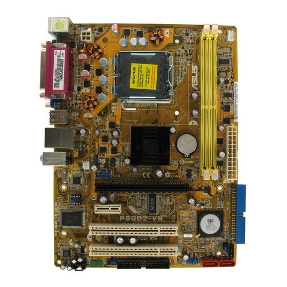
Page 14: Motherboard Layout
1.2.3 Motherboard layout ATX12V SPDIF_O1 F_USB12 USBPW12 USBPW34 LAN_USB34 REALTEK SPDIF_O2 VT6307 PCIEX1_1 ALC880 AAFP 23.0 cm (9.0 in) CPU_FAN LGA775 649DX PCIEX16 PCI1 PCI2 CR2032 3V Lithium Cell CMOS Power USBPW56 USBPW78 IE1394_1 USB56 USB78 Chapter 1: Hardware information CHA_FAN SATA2 SATA4... -
Page 15: Layout Contents
6. Line In port 7. Line Out port 8. Microphone port 9. Rear Speaker Out port 10. USB 2.0 ports 3 and 4 11. USB 2.0 ports 1 and 2 12. PS/2 keyboard port ASUS P5SD2-FM Page 1-14 1-20 1-20 Page 1-21... - Page 16 Internal connectors 1. Floppy disk drive connector (34-1 pin FLOPPY) 2. Power LED connector (3-1 pin PLED) 3. IDE connectors (40-1 pin PRI_IDE, SEC_IDE) 4. Serial ATA connectors (7-pin SATA1 [black], SATA2 [black]) 5. CPU and Chassis fan connectors (4-pin CPU_FAN, 3-pin CHA_FAN) 6.
-
Page 17: Central Processing Unit (Cpu)
ASUS will shoulder the cost of repair only if the damage is shipment/transit-related. • Keep the cap after installing the motherboard. ASUS will process Return Merchandise Authorization (RMA) requests only if the motherboard comes with the cap on the LGA775 socket. - Page 18 Press the load lever with your thumb (A), then move it to the left (B) until it is released from the retention tab. Retention tab Load lever To prevent damage to the socket pins, do not remove the PnP cap unless you are installing a CPU.
- Page 19 Under the Advanced Menu, make sure that the item Hyper-Threading Technology is set to Enabled. The item appears only if you installed a CPU that supports Hyper-Threading Technology. Reboot the computer. ASUS P5SD2-FM ® ® Pentium 4 CPUs in the 775-land package ®...
-
Page 20: Installing The Cpu Heatsink And Fan
1.3.2 Installing the CPU heatsink and fan ® ® The Intel Pentium 4 LGA775 processor requires a specially designed heatsink and fan assembly to ensure optimum thermal condition and performance. • When you buy a boxed Intel includes the CPU fan and heatsink assembly. If you buy a CPU separately, make sure that you use only Intel fan. - Page 21 Connect the CPU fan cable to the connector on the motherboard labeled CPU_FAN. P5SD2-FM CPU Fan Connector Do not forget to connect the CPU fan connector! Hardware monitoring errors can occur if you fail to plug this connector. ASUS P5SD2-FM...
-
Page 22: Uninstalling The Cpu Heatsink And Fan
1.3.3 Uninstalling the CPU heatsink and fan To uninstall the CPU heatsink and fan: Disconnect the CPU fan cable from the connector on the motherboard. Rotate each fastener counterclockwise. Pull up two fasteners at a time in a diagonal sequence to disengage the heatsink and fan assembly from the motherboard. - Page 23 Remove the heatsink and fan assembly from the motherboard. Rotate each fastener clockwise to reset the orientation. The narrow end of the groove should point outward after resetting. (The photo shows the groove shaded for emphasis.) ASUS P5SD2-FM Narrow end of the groove 1-13...
-
Page 24: System Memory
The motherboard comes with two 240-pin Double Data Rate (DDRII) Dual Inline Memory Modules (DIMM) sockets. The following figure illustrates the location of the sockets: P5SD2-FM 240-pin DDR DIMM Sockets 1.4.2 Memory Configurations You may install 256 MB, 512 MB and 1 GB unbuffered non-ECC DDR DIMMs into the DIMM sockets using the memory configurations in this section. -
Page 25: Installing A Dimm
Support the DIMM lightly with your fingers when pressing the retaining clips. The DIMM might get damaged when it flips out with extra force. Remove the DIMM from the socket. ASUS P5SD2-FM DDR2 DIMM notch Unlocked retaining clip DDR2 DIMM notch... -
Page 26: Expansion Slots
Expansion slots In the future, you may need to install expansion cards. The following sub-sections describe the slots and the expansion cards that they support. Make sure to unplug the power cord before adding or removing expansion cards. Failure to do so may cause you physical injury and damage motherboard components. -
Page 27: Interrupt Assignments
When using PCI cards on shared slots, ensure that the drivers support “Share IRQ” or that the cards do not need IRQ assignments; otherwise, conflicts will arise between the two PCI groups, making the system unstable and the card inoperable. ASUS P5SD2-FM Standard Function System Timer Keyboard Controller... -
Page 28: Pci Express X1
1.5.4 PCI Express x1 This motherboard supports PCI Express x1 network cards, SCSI cards and other cards that comply with the PCI Express specifications. The figure shows a network card installed on the PCI Express x1 slot. 1.5.5 PCI slots This motherboard has three PCI slots. -
Page 29: Clear Rtc Ram Clrtc
Except when clearing the RTC RAM, never remove the cap on CLRTC jumper default position. Removing the cap will cause system boot failure! P5SD2-FM Clear RTC RAM You do not need to clear the RTC when the system hangs due to overclocking. - Page 30 7. Replace the jumper cap from pins 2-3 to pins 1-2. 8. Reboot your computer. 9. Hold down the <Del> key during the boot process and enter BIOS set-up to re-enter data. P5SD2-FM BIOS Recovery Setting CPU_SEL For new Intel CPU types Default setting pin 1-2 For the current CPU types there is no need to change this jumper.
-
Page 31: Usb Device Wake-Up
Password Skip P5SD2-FM Clear Password Setting USB device wake-up (3-pin USBPW12, USBPW34, USBPW56, USBPW78) Set these jumpers to +5V to wake up the computer from S1 sleep mode (CPU stopped, DRAM refreshed, system running in low power mode) using the connected USB devices. Set to +5VSB to wake up from S3 and S4 sleep modes (no power to CPU, DRAM in slow refresh, power supply in reduced power mode). -
Page 32: Connectors
Connectors 1.7.1 Rear panel connectors Serial port. This 9-pin COM1 port is for pointing devices or other serial devices. IEEE 1394a port. This 6-pin IEEE 1394a port provides high-speed connectivity for audio/video devices, storage peripherals, PCs, or portable devices. LAN (RJ-45) port. This port allows connection to a Local Area Network (LAN) through a network hub. - Page 33 11. USB 2.0 ports 1 and 2. These two 4-pin Universal Serial Bus (USB) ports are available for connecting USB 2.0 devices. 12. S/PDIF out jack. This jack connects to external audio output devices. ASUS P5SD2-FM 4-channel 6-channel Line In...
-
Page 34: Internal Connectors
Pin 5 on the connector is removed to prevent incorrect cable connection when using an FDD cable with a covered Pin 5. P5SD2-FM Floppy Disk Drive Connector Power LED connector (3-1 pin PLED) This 3-1 pin connector is for the system power LED. Connect the 3-pin power LED cable from the system chassis to this connector. -
Page 35: Ide Connectors (40-1 Pin Pri_Ide, Sec_Ide)
Ultra DMA cable connector. This prevents incorrect insertion when you connect the IDE cable. • Use the 80-conductor IDE cable for Ultra DMA 100/66 IDE devices. P5SD2-FM IDE Connectors ASUS P5SD2-FM NOTE: Orient the red markings (usually zigzag) on the IDE ribbon cable to PIN 1. -
Page 36: Serial Ata Connectors (7-Pin Sata1 [Black], Sata2 [Black])
These connectors are set to Standard IDE configuration by default. In Standard IDE mode, you can connect Serial ATA boot/data hard disk drives to these connectors. P5SD2-FM SATA connectors Important notes on Serial ATA • The Serial ATA RAID feature (RAID 0, RAID 1) is available only if you are using Windows •... -
Page 37: Cpu And Chassis Fan Connectors (4-Pin Cpu_Fan, 3-Pin Cha_Fan)
DO NOT place jumper caps on the fan connectors. P5SD2-FM Fan Connectors Speaker out connector (4-pin SPEAKER) This connector is for the case-mounted speaker and allows you to hear system beeps and warnings. P5SD2-FM Speaker Out Connector ASUS P5SD2-FM CHA_FAN Rotation +12V... -
Page 38: Usb Connectors (10-1 Pin Usb56, Usb78)
These USB connectors comply with USB 2.0 specification that supports up to 480 Mbps connection speed. P5SD2-FM USB 2.0 Connectors Never connect a 1394 cable to the USB connectors. Doing so will damage the... -
Page 39: Atx Power Connector (24-Pin Eatxpwr, 4-Pin Atx12V)
The ATX 12 V Specification 2.0-compliant PSU passed the motherboard power requirement test with the following configuration: Memory Graphics card Parallel ATA devices : Serial ATA device Optical drives SCSI devices P5SD2-FM ATX Power Connectors ASUS P5SD2-FM Intel ® Pentium ® 4 3.6 GHz 512 MB DDR (x 2) -
Page 40: Internal Audio Connector (4-Pin Aux)
This connector is for a chassis-mounted front panel audio I/O module that supports AC ‘97 audio standard. Connect one end of the front panel audio I/ O module cable to this connector. P5SD2-FM Analog Front Panel Connector 1-32 AUX (White) -
Page 41: System Panel Connector (10-1 Pin F_Panel)
12. System panel connector (10-1 pin F_PANEL) This connector supports several chassis-mounted functions. P5SD2-FM System Panel Connector The sytem panel connector is color-coded for easy connection. Refer to the connector description below for details. • System power LED (Green 2-pin PLED) This 3-pin connector is for the system power LED. - Page 42 1-34 Chapter 1: Hardware information...
-
Page 43: Chapter 2: 2.1 Bios Setup
This chapter tells how to change the system settings through the BIOS Setup menus. Detailed descriptions of the BIOS parameters are also provided. BIOS setup... -
Page 44: Bios Setup Program
BIOS setup program This motherboard supports a programmable firmware chip that you can update using the provided utility described in section “2.1 Managing and updating your BIOS.” Use the BIOS Setup program when you are installing a motherboard, reconfiguring your system, or prompted to “Run Setup.” This section explains how to configure your system using this utility. -
Page 45: Bios Menu Screen
At the bottom right corner of a menu screen are the navigation keys for that particular menu. Use the navigation keys to select items in the menu and change the settings. Some of the navigation keys differ from one screen to another. ASUS P5SD2-FM Configuration fields [10:55:25] [FRI,03/10/2006] [1.44M, 3.5 in]... -
Page 46: Menu Items
[Thu 01/27/2005] Legacy Diskette A [1.44M, 3.5 in] Primary IDE Master : [ST320410A] Primary IDE Slave : [ASUS CD-S520/A] Secondary IDE Master : [Not Detected] Secondary IDE Slave : [Not Detected] Third IDE Master : [Not Detected] Third IDE Slave... -
Page 47: Main Menu
2.3.3 Legacy Diskette A [Disabled] Sets the type of floppy drive installed. Configuration options: [Disabled] [360K, 5.25 in.] [1.2M , 5.25 in.] [720K , 3.5 in.] [1.44M, 3.5 in.] [2.88M, 3.5 in.] ASUS P5SD2-FM [10:55:25] [FRI,03/10/2006] [Disabled] [ST320410A] [ASUS CD-S520/A]... -
Page 48: Primary, Third And Fourth Ide Master/Slave
2.3.4 Primary, Secondary, Third, and Fourth IDE Master/Slave While entering Setup, the BIOS automatically detects the presence of IDE devices. There is a separate sub-menu for each IDE device. Select a device item then press <Enter> to display the IDE device information. Primary IDE Master Device Vendor... -
Page 49: Pio Mode [Auto]
Configuration options: [Auto] [Disabled] [Enabled] 32Bit Data Transfer [Enabled] Enables or disables 32-bit data transfer. Configuration options: [Disabled] [Enabled] 2.3.5 SATA Mode Selection [4P(IDE)+4S(IDE)] Allows you to select the SATA mode. Configuration options: [Disabled] [4P(IDE)+4S(RAID)] [4P(IDE)+4S(IDE)] [2P2S(IDE)+2S(RAID)] [2P2S(IDE)+2S(AHCI)] [4P(IDE)+2S(RAID)] [4P(IDE)+2S(AHCI)] ASUS P5SD2-FM... -
Page 50: System Information
2.3.6 System Information This menu gives you an overview of the general system specifications. The BIOS automatically detects the items in this menu. AMIBIOS Version : 0121 Build Date : 01/17/06 Processor Type : Genuine Intel(R) CPU 2.80 GHz Speed : 2800 MHz Count System Memory... -
Page 51: Advanced Menu
The Advanced menu items allow you to change the settings for the CPU and other system devices. Take caution when changing the settings of the Advanced menu items. Incorrect field values can cause the system to malfunction. CPU Configuration Chipset Onboard Devices Configuration PCI PnP USB Configuration ASUS P5SD2-FM Configure CPU. -
Page 52: Cpu Configuration
2.4.1 CPU Configuration The items in this menu show the CPU-related information that the BIOS automatically detects. Configure advanced CPU Settings Manufacturer : Intel Brand String : Genuined Intel (R) CPU 2.80 GHz Frequency : 2800 MHz FSB Speed 800 MHz Cache L1 : 32 KB Cache L2... -
Page 53: Chipset
Configuration options: [100] ~ [355] 2.4.2 Chipset The Chipset menu allows you to change the advanced chipset settings. Select an item then press <Enter> to display the sub-menu. NorthBridge SIS649 Configuration SouthBridge SiS965/SiS965L Configuration ASUS P5SD2-FM Options for NB 2-11... -
Page 54: Chipset
NorthBridge SIS649 Chipset Configuration Primary Graphics Adapter CPU FSB Set To Chipset Timing Auto Detect DRAM Frequency CPU:DRAM Frequency Ratio Real CPU FSB:DRAM = 800(200*4): 533(266*2) MHz DRAM CAS# Latency Dual Core PATCH Primary Graphics Adapter [PCI Express] Allows selection of the graphics controller to use as a primary boot device. Configuration options: [PCI] [PCI Express] CPU FSB Set To Chipset Timing [FSB: 533MHz] Displays auto-detected CPU FSB information. - Page 55 MAC/PHY Interface Mode [MII/GMII Mode] Enables or disables the onboard SiS966 LAN controller. Configuration options: [Disabled] [Enabled] Onboard LAN Boot ROM [Disabled] Enables or disables the onboard LAN boot ROM feature. Configuration options: [Disabled] [Enabled] ASUS P5SD2-FM [Enabled] [Enabled] [MII/GMII Mode] [Disabled] 2-13...
-
Page 56: Onboard Devices Configuration
2.4.3 Onboard Devices Configuration Configure ITE8712 Super IO Chipset Serial Port1 Address Serial Port1 Mode Onboard 1394 Controller Serial Port1 Address [3F8/IRQ4] Allows you to select the Serial Port1 base address. Configuration options: [Disabled] [3F8/IRQ4] [3E8/IRQ4] [2E8/IRQ3] Serial Port1 Mode [Normal] Allows you to select the Serial Port1 mode. -
Page 57: Pci Pnp
[Yes] and if you install a Plug and Play operating system, the operating system configures the Plug and Play devices not required for boot. Configuration options: [No] [Yes] ASUS P5SD2-FM No: Lets the BIOS configure all the devices in the system. -
Page 58: Allocate Irq To Pci Vga [Yes]
Allocate IRQ to PCI VGA [Yes] When set to [Yes], BIOS assigns an IRQ to PCI VGA card if the card requests for an IRQ. When set to [No], BIOS does not assign an IRQ to the PCI VGA card even if requested. -
Page 59: Usb Configuration
Allows you to set the USB 2.0 controller mode to HiSpeed (480 Mbps) or FullSpeed (12 Mbps). Configuration options: [FullSpeed] [HiSpeed ] BIOS EHCI Hand-Off [Enabled] Allows you to enable or disable the BIOS EHCI Hand-Off.. Configuration options: [Disabled] [Enabled] ASUS P5SD2-FM [Enabled] [Enabled] [Enabled] [HiSpeed]... -
Page 60: Power Menu
Power menu The Power menu items allow you to change the settings for the ACPI and Advanced Power Management (APM). Select an item then press <Enter> to display the configuration options. ACPI Aware O/S Suspend Mode Repost Video on S3 Resume ACPI 2.0 Support ACPI APIC Support APM Configuration... -
Page 61: Apm Configuration
Thus, connection cannot be made on the first try. Turning an external modem off and then back on while the computer is off causes an initialization string that turns the system on. ASUS P5SD2-FM [On/Off] Select Power button functionality. -
Page 62: Hardware Monitor
The onboard hardware monitor automatically detects the voltage output through the onboard voltage regulators. Smart Q-Fan Function [Enabled] Allows you to enable or disable the ASUS Q-Fan feature that smartly adjusts the fan speeds for more efficient system operation. Configuration options: [Disabled] [Enabled] 2-20 C/122.5... -
Page 63: Boot Menu
These items specify the boot device priority sequence from the available devices. The number of device items that appears on the screen depends on the number of devices installed in the system. Configuration options: [Disabled] [xxx Drive] ASUS P5SD2-FM Specifies the Boot Device Boot Priority sequence. -
Page 64: Boot Settings Configuration
This allows you to enable or disable the full screen logo display feature. Configuration options: [Disabled] [Enabled] Set this item to [Enabled] to use the ASUS MyLogo™ feature. Bootup Num-Lock [On] Allows you to select the power-on state for the NumLock. -
Page 65: Security
To change the supervisor password, follow the same steps as in setting a user password. To clear the supervisor password, select the Change Supervisor Password then press <Enter>. The message “Password Uninstalled ”appears. ASUS P5SD2-FM <Enter> to change password. <Enter> again to disabled password. -
Page 66: Change User Password
If you forget your BIOS password, you can clear it by erasing the CMOS Real Time Clock (RTC) RAM. See section “1.6 Jumpers” for information on how to erase the RTC RAM. After you have set a supervisor password, the other items appear to allow you to change other security settings. -
Page 67: Clear User Password
Discard Changes Load Setup Defaults Pressing <Esc> does not immediately exit this menu. Select one of the options from this menu or <F10> from the legend bar to exit. ASUS P5SD2-FM Exit system setup after saving the changes. F10 key can be used for this operation. -
Page 68: Discard Changes
Exit & Save Changes Once you are finished making your selections, choose this option from the Exit menu to ensure the values you selected are saved to the CMOS RAM. An onboard backup battery sustains the CMOS RAM so it stays on even when the PC is turned off.
Need help?
Do you have a question about the P5SD2-FM and is the answer not in the manual?
Questions and answers