Texecom Premier LCD Installation Manual
Hide thumbs
Also See for Premier LCD:
- User manual (36 pages) ,
- Function manual (4 pages) ,
- Master user manual (64 pages)

Related Manuals for Texecom Premier LCD


Summary of Contents for Texecom Premier LCD
- Page 1 THANK YOU FOR VOTING TEXECOM THANK YOU FOR VOTING TEXECOM THANK YOU FOR VOTING TEXECOM THANK YOU FOR VOTING TEXECOM INSTALLATION MANUAL Remote Keypads...
-
Page 2: Table Of Contents
Premier LCD & LCDL Installation Manual Contents Contents 1. Overview.................... 3 General ........................3 Keypad PCB Layout .....................4 2. Installation ..................6 Mounting........................6 Connecting Keypads ....................7 Wiring the Network ..................7 Network Connections ...................8 Cable Distances ....................8 Overcoming Voltage Drop ................9 Installing a Power Supply ................9 Selecting an Address ..................10... -
Page 3: Overview
LCDL LCDL Installation Manual LCDL Overview 1. Overview General The Premier LCD and LCDL keypads are only compatible with the following control panels: • Premier 888 • Premier 8168 Any combination of Premier LCD and LCDL keypads can be used. -
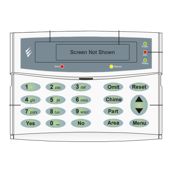
Page 4: Keypad Pcb Layout
Premier LCD & LCDL Installation Manual Overview Keypad PCB Layout Network Tamper Output Terminals Switch Address Switch Piezo Sounder NE TWORK Zones 1 & 2 Speaker Output LCDL Only) Premier LCDL Premier LCD Large Display Display Power Programmable Screen Not Shown ‘Info.’... - Page 5 These terminals can be used for connecting up to one 16Ω or two 8Ω loudspeakers (see page 12 for wiring details). Premier LCD & LCDL Display The 32-character display is used to show the status of the system and to view system data.
-
Page 6: Installation
Premier LCD & LCDL Installation Manual Installation 2. Installation Mounting Open the keypad by carefully inserting a small flat-blade screwdriver into each slot at the base of the unit. Gently push the screwdriver to ease the retaining clips upward, DO NOT LEVER OR TWIST. Excessive force is NOT required. The front flap and front cover can now be removed. -
Page 7: Connecting Keypads
Premier LCD & LCDL Installation Manual Installation Connecting Keypads Before connecting keypads, isolate ALL power from the control panel (AC Mains and Battery). Do not continue if there is power still present on the control panel. ! " Connecting a keypad with power still present on the control panel may damage the keypad or control panel and invalidate any warranty. -
Page 8: Network Connections
Premier LCD & LCDL Installation Manual Installation Network Connections Cable Distances The maximum recommended distance for keypads when using standard 7/0.2 alarm cable is: • 250m for each branch when using the star (parallel) configuration • When using a daisy chain (series) configuration the maximum distance will depend on the number of devices connected on the chain. -
Page 9: Overcoming Voltage Drop
Premier LCD & LCDL Installation Manual Installation Overcoming Voltage Drop There are several ways to overcome voltage drop: • Use thicker lower resistance cable. Standard 7/0.2 alarm cable has a resistance of 8Ω per 100m • Double up on the power connections – this will require using a 6 or 8-core cable rather than a 4-core cable •... -
Page 10: Selecting An Address
Premier LCD & LCDL Installation Manual Installation Selecting an Address Each keypad must be assigned a different address using the DIL switches located on the left hand side of the PCB. The table below shows the keypad addressing: Address DIL 1... -
Page 11: Wiring Zones To The Keypad
Premier LCD & LCDL Installation Manual Installation Wiring Zones to the Keypad The keypad has 2 fully programmable zones, ensure that no more than 5 detectors are connected to each zone. Please refer to the Premier 888/8168 Installation Manual for programming details. -
Page 12: Connecting Speakers To The Keypad
Premier LCD & LCDL Installation Manual Installation Connecting Speakers to the Keypad The Premier LCDL has an output on it that can be used to drive loudspeakers. The output is capable of driving up to one 16Ω or two 8Ω loudspeakers as shown below: The speakers should be tested to ensure correct operation (see page 13 for details). -
Page 13: Other Features
LCD & LCD-Pro Installation Manual Installation Other Features Programmable ‘Info.’ LED The ‘Info.’ LED on the front of the keypad can be programmed to mimic the keypad output or show the armed status of an area. For details on programming the ‘Info.’ LED, please refer to the Premier 888/8168 Installation Manual. -
Page 14: Specifications
Premier LCD & LCDL Installation Manual Specifications 3. Specifications Electrical Operating Voltage 10 - 13.7V Current Consumption Quiescent 35mA In Alarm 85mA Network 4-wire standard 7/0.2 alarm cable up to 250m. Star, Daisy Chain or any combination of the two... -
Page 15: Physical
LCDL keypads are covered by a two-year warranty against defects in material or workmanship. As the Premier LCD and LCDL keypads are not a complete alarm system but only a part thereof, Texecom cannot accept responsibility or liability for any damages whatsoever based on a claim that the Premier LCD or LCDL failed to function correctly. - Page 16 Texecom Limited, Bradwood Court, St. Crispin Way, Haslingden, Lancashire BB4 4PW, England. Technical Support: Tel: +44 (0)1706 234833 Tel: +44 (0)1706 234811 Fax: +44 (0)1706 213187 INS180...
Need help?
Do you have a question about the Premier LCD and is the answer not in the manual?
Questions and answers