Table of Contents
Advertisement
Quick Links
Unpacking
Thank you for buying the MSI
to make sure your motherboard box contains the following items. If something is
missing, contact your dealer as soon as possible.
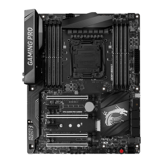
Motherboard
Quick Guide
I/O Shield
RGB LED Extension Cable 40cm x1
RGB LED Extension Cable 80cm x1
* These pictures are for reference only and may vary without notice.
** The packing contents may vary according to the country you purchased.
X99A GAMING PRO CARBON
®
Drivers & Utilities
Disc
SLI Bridge
Connector x2
Door Hanger
motherboard. Check
Motherboard User
Guide
SATA Cable x6
SATA Cable Labels
Case Badge
1
Unpacking
Advertisement
Table of Contents

Related Manuals for MSI X99A GAMING PRO CARBON


Summary of Contents for MSI X99A GAMING PRO CARBON
-
Page 1: Unpacking
Unpacking Thank you for buying the MSI X99A GAMING PRO CARBON motherboard. Check ® to make sure your motherboard box contains the following items. If something is missing, contact your dealer as soon as possible. Drivers & Utilities Motherboard User... -
Page 2: Safety Information
Safety Information The components included in this package are prone to damage from electrostatic discharge (ESD). Please adhere to the following instructions to ensure successful computer assembly. Ensure that all components are securely connected. Loose connections may cause the computer to not recognize a component or fail to start. Hold the motherboard by the edges to avoid touching sensitive components. -
Page 3: Quick Start
Quick Start Preparing Tools and Components Intel LGA 2011-3 CPU ® CPU Fan Thermal Paste DDR4 Memory Power Supply Unit Chassis SATA Hard Disk Drive Graphics Card SATA DVD Drive A Package of Screws Phillips Screwdriver Quick Start... -
Page 4: Installing A Processor
Installing a Processor https://youtu.be/QnwHWBx3NnE Quick Start... -
Page 5: Installing Ddr4 Memory
Installing DDR4 memory http://youtu.be/T03aDrJPyQs Quick Start... -
Page 6: Connecting The Front Panel Header
Connecting the Front Panel Header http://youtu.be/DPELIdVNZUI HDD LED + Power LED + HDD LED - Power LED - Reset Switch Power Switch Reset Switch Power Switch JFP1 Reserved No Pin JFP1 HDD LED - HDD LED HDD LED + POWER LED - POWER LED POWER LED + Quick Start... -
Page 7: Installing The Motherboard
Installing the Motherboard Quick Start... -
Page 8: Installing Sata Drives
Installing SATA Drives http://youtu.be/RZsMpqxythc Quick Start... -
Page 9: Installing A Graphics Card
Installing a Graphics Card http://youtu.be/mG0GZpr9w_A Quick Start... -
Page 10: Connecting Peripheral Devices
Connecting Peripheral Devices Quick Start... -
Page 11: Connecting The Power Connectors
Connecting the Power Connectors http://youtu.be/gkDYyR_83I4 JPWR1 JPWR2 Quick Start... -
Page 12: Power On
Power On Quick Start... -
Page 13: Table Of Contents
Contents Unpacking ......................1 Safety Information ....................2 Quick Start ......................3 Preparing Tools and Components ................3 Installing a Processor ..................... 4 Installing DDR4 memory ..................5 Connecting the Front Panel Header ............... 6 Installing the Motherboard ..................7 Installing SATA Drives..................... - Page 14 JUSB3~4: USB 2.0 Connectors ................45 JLED1: RGB LED connector ................. 45 CPUFAN1,SYSFAN1~3,PUMPFAN1: Fan Connectors .......... 46 JAUD1: Front Audio Connector ................47 JCI1: Chassis Intrusion Connector ............... 47 BIOS1: Multi-BIOS Switch ..................48 POWER1, RESET1: Power Button, Reset Button ..........49 JBAT1: Clear CMOS (Reset BIOS) Jumper ............
- Page 15 Nahimic 2 ......................95 XSplit Gamecaster V2 ................... 99 Intel Extreme Tuning Utility ................103 ® RAID Configuration .................... 104 Using Intel Rapid Storage Technology Option ROM ......... 104 ® Degraded RAID Array ..................107 Troubleshooting ....................109 Regulatory Notices .................... 110 Contents...
-
Page 16: Specifications
Quad channel memory architecture Supports Intel Extreme Memory Profile (XMP) ® * For the latest information about memory, please visit http://www.msi.com 4x PCIe 3.0 x16 slots* Support x16/ x0/ x0/ x0, x16/ x16/ x0/ x0, x16/ x16/ x0/ ƒ x8, x8/ x16/ x8/ x8 with the CPU that supports 40 PCIe lanes. - Page 17 Continued from previous page Intel X99 Chipset ® 10x SATA 6Gb/s ports (2 ports from SATAe port) SATA1~6 support RAID 0, RAID 1, RAID 5 and RAID 10 ƒ SATA7~10 only support IDE mode and AHCI mode ƒ 1x M.2 slot (Key M)* Supports up to PCIe 3.0 x4 and SATA 6Gb/s ƒ...
- Page 18 Continued from previous page 1x 24-pin ATX main power connector 1x 8-pin ATX 12V power connector 10x SATA 6Gb/s connectors 1x SATA Express connector 1x M.2 slot 1x U.2 port 2x USB 2.0 connectors (supports additional 4 USB 2.0 ports) 2x USB 3.1 Gen1 connectors (supports additional 4 USB 3.1 Gen1 ports) 1x USB 3.1 Gen1 Type-C port...
- Page 19 Continued from previous page Drivers COMMAND CENTER LIVE UPDATE 6 FAST BOOT SUPER CHARGER GAMING APP SMART UTILITIES M-CLOUD RAMDISK Software GAMING LAN MANAGER USB SPEED UP Nahimic 2 XSplit Gamecaster V2 Intel Extreme Tuning Utility ® Norton Internet Security Solution ™...
- Page 20 Continued from previous page AUDIO BOOST 3 Isolated Audio PCB ƒ EMI Shielding ƒ High Quality Audio Capacitors ƒ Golden Audio Connectors ƒ GAME BOOST Easy Overclocking ƒ 7 Gear Clock Change ƒ GAMING LAN Intel Gigabit Ethernet ® ƒ GAMING Network Manager power by cFos ƒ...
- Page 21 ƒ Military Class Stability and Reliability ƒ ESD Protection ˜ EMI Protection ˜ Humidity Protection ˜ Circuit Protection ˜ MSI Exclusive High Temperature Protection ˜ Features VGA Armor Slot ˜ COMMAND CENTER System Monitor ƒ Smart Fan Control ƒ RAMDISK...
- Page 22 Continued from previous page DDR4 BOOST 2 Support Quad-Channel DDR4 Memory Support ƒ Isolated DDR4 Circuit Design ƒ DDR4 XMP Ready ƒ Steel Armor Ready ƒ PCI Express 3.0 Support 3-Way Nvidia SLI Support ƒ 3-Way AMD CrossFire Support ƒ Multi-GPU with Steel Armor USB 3.1 Gen2 Type-A/ Type-C Ready Specification...
-
Page 23: Block Diagram
Block Diagram 4 Channel DDR4 Memory Processor PCI Express Bus Switch PCIe x1 slot PCIe x1 slot 1x U.2 5x USB 3.1 Gen1 DMI 2.0 1x M.2 8x USB 2.0 1x SATA Express Switch 2x SATA 6Gb/s X99 PCH VL805 4x USB 3.1 Gen1 PCI Express Bus ASMEDIA... -
Page 24: Rear I/O Panel
Rear I/O Panel Audio Ports PS/2 USB 3.1 Gen2 Optical S/PDIF-Out USB 3.1 Gen1 USB 2.0 USB 2.0 Clear CMOS USB 3.1 Gen2 Type-C Clear CMOS button - Power off your computer. Press and hold the Clear CMOS button for about 5-10 seconds to reset BIOS to default values. LAN Port LED Status Table Link/ Activity LED Speed LED... -
Page 25: Realtek Hd Audio Manager
Realtek HD Audio Manager After installing the Realtek HD Audio driver, the Realtek HD Audio Manager icon will appear in the system tray. Double click on the icon to launch. Device Selection Advanced Settings Jack Status Application Enhancement Main Volume Connector Strings Profiles... - Page 26 Audio jacks to headphone and microphone diagram Audio jacks to stereo speakers diagram AUDIO INPUT Audio jacks to 7.1-channel speakers diagram AUDIO INPUT Rear Front Side Center/ Subwoofer Rear I/O Panel...
-
Page 27: Overview Of Components
Overview of Components CPUFAN1 DIMM1 DIMM2 JPWR2 DIMM3 PUMPFAN1 DIMM4 CPU Socket SYSFAN1 DIMM8 DIMM7 DIMM6 DIMM5 SYSFAN2 JPWR1 JUSB1 JCI1 M2_1 JBAT1 USB5 PCI_E1 JUSB2 PCI_E2 SATA1_2 PCI_E3 SATA3_4 PCI_E4 SATA7_8 PCI_E5 BIOS1 U2_1 JTPM1 JFP2 PCI_E6 SATA9 JSLOW1 SATA10 JAUD1 RESET1... - Page 28 Component Contents Port Name Port Type Page BIOS1 Multi-BIOS Switch CPUFAN1,SYSFAN1~3,PUMPFAN1 Fan Connectors CPU Socket LGA2011-3 DIMM1~8 DIMM Slots JAUD1 Front Audio Connector JBAT1 Clear CMOS (Reset BIOS) Jumper JCI1 Chassis Intrusion Connector JFP1, JFP2 Front Panel Connectors JLED1 RGB LED connector JPWR1~2 Power Connectors JSLOW1...
-
Page 29: Cpu Socket
Always unplug the power cord from the power outlet before installing or removing the CPU. Please retain the CPU protective cap after installing the processor. MSI will deal with Return Merchandise Authorization (RMA) requests if only the motherboard comes with the protective cap on the CPU socket. -
Page 30: Dimm Slots
DIMM Slots DIMM3 DIMM6 DIMM1 DIMM8 Channel A Channel B Channel D Channel C DIMM4 DIMM5 DIMM2 DIMM7 Memory module installation recommendation DIMM3 DIMM1 DIMM1 DIMM5 DIMM7 DIMM3 DIMM5 DIMM1 DIMM3 DIMM6 DIMM2 DIMM7 DIMM1 Overview of Components... - Page 31 DIMM4 DIMM5 DIMM3 DIMM6 DIMM2 DIMM7 DIMM1 DIMM8 Important Always insert a memory module in the DIMM1 slot first. To ensure system stability for Dual/ Triple/ Quad channel mode, memory modules must be of the same type, number and density. And for every channel, the odd number DIMM slot must to be installed first.
-
Page 32: Pci_E1~6: Pcie Expansion Slots
With MSI PCI-E Ambient Light feature, you will be able to easily find out which PCIe x16 slot is operating with full 3.0 x16 speed. Red PCIe LED ambient light indicate the PCIe x16 slot is operating at full 3.0 x16 speed, and white PCIe LED ambient light... - Page 33 Multiple graphics cards installation recommendation x16*/ 8** x16* x8** x8** x16* x8** * For the CPU with 40 PCIe lanes support. ** For the CPU with 28 PCIe lanes support. Overview of Components...
- Page 34 Installing SLI graphics cards For power supply recommendations for SLI configurations, please refer to the user guide of your graphics card to make sure you meet all the system requirements. To install SLI graphics cards: Turn off your computer and disconnect the power cord, install two graphics cards into the PCI_E1 and PCI_E3 slots.
-
Page 35: Sata1~10: Sata 6Gb/S Connectors
SATA1~10: SATA 6Gb/s Connectors These connectors are SATA 6Gb/s interface ports. Each connector can connect to one SATA device. SATA2 SATA1 SATA4 SATA3 SATA8 SATA7 SATA9 SATA6 SATA10 SATA5 SE1_65: SATAe Connector This connector is a SATAe (SATA Express) interface port. Each SATAe connector can be used with a single SATAe device or two legacy SATA devices. -
Page 36: M2_1: M.2 Slot (Key M)
M2_1: M.2 Slot (Key M) Important Intel RST only supports PCIe M.2 SSD with UEFI ROM, ® does not support Legacy ROM. Video Demonstration Watch the video to learn how to Install M.2 module. http://youtu.be/JCTFABytrYA Installing M.2 module Remove the screw from the base screw. -
Page 37: U2_1: U.2 Connector
U2_1: U.2 Connector This connector is a U.2 interface port. Each connector can connect to one PCIe 3.0 x4 NVMe storage device. Video Demonstration Watch the video to learn how to Install U.2 SSD. http://youtu.be/KgFvKDxymvw Installing U.2 SSD Connect the U.2 cable to the U.2 connector on the motherboard. - Page 38 U.2/ M.2/ SATAe & SATA combination table Slot Available SATA/ SATAe connectors PCI_E6 Installed Empty U2_1 Disabled Empty Installed M2_1 SATA/ PCIe* SATA PCIe/ Empty SATA/ PCIe* Empty ─ ─ ✓ ─ ✓ SE1_65 ✓ ✓ ✓ ✓ ✓ SATA1 ✓...
- Page 39 M.2 slots with examples of various combination possibilities The combination possibilities below are set up in empty PCI_E6 slot condition. 1xU.2+ 1xM.2 PCIe 2.0+ 8xSATA 1xU.2+ 1xM.2 SATA+ 8xSATA PCIe 2.0 SATA SATA9 SATA9 SATA10 SATA10 1xM.2 PCIe 3.0+ 1xSATAe+ 8xSATA 1xM.2 PCIe 3.0+ 10xSATA PCIe 3.0 PCIe 3.0...
-
Page 40: Oc1: Game Boost Knob
Note: The above table is for Haswell processors only. If you want to learn about the CPU frequency of each stage in GAME BOOST mode for Broadwell processors, please visit: www.msi.com Power on and then GAME BOOST will automatically overclock processor depending on the stage you selected. -
Page 41: Jtpm1: Tpm Module Connector
Rotate the GAME BOOST knob to 0 and then power on. The configuration parameters will be returned to its default values. Important You can also control the GAME BOOST function in BIOS Setup or with MSI COMMAND CENTER software. In order to optimize performance and improve system stability, when you activate the GAME BOOST function, please leave the settings in the BIOS >... -
Page 42: Jpwr1~2: Power Connectors
JPWR1~2: Power Connectors These connectors allow you to connect an ATX power supply. JPWR2 Ground +12V Ground +12V Ground +12V Ground +12V +3.3V +3.3V +3.3V -12V Ground Ground PS-ON# Ground Ground Ground JPWR1 Ground Ground PWR OK 5VSB +12V +12V +3.3V Ground Important... -
Page 43: Jfp1, Jfp2: Front Panel Connectors
JFP1, JFP2: Front Panel Connectors These connectors connect to the switches and LEDs on the front panel. JFP1 HDD LED + Power LED + HDD LED - Power LED - Reset Switch Power Switch Reset Switch Power Switch Reserved No Pin Speaker - Buzzer + JFP2... -
Page 44: Usb5: Usb 3.1 Gen1 Type-C Connector
However, when you boot the computer into Windows , you will need to install the MSI SUPER CHARGER application to turn ON/ ®... -
Page 45: Jusb3~4: Usb 2.0 Connectors
JUSB3~4: USB 2.0 Connectors These connectors allow you to connect USB 2.0 ports on the front panel. USB0- USB1- USB0+ USB1+ Ground Ground No Pin Important Note that the VCC and Ground pins must be connected correctly to avoid possible damage. -
Page 46: Cpufan1,Sysfan1~3,Pumpfan1: Fan Connectors
CPUFAN1,SYSFAN1~3,PUMPFAN1: Fan Connectors Fan connectors can be classified as PWM (Pulse Width Modulation) Mode and Voltage Mode. PWM Mode fan connectors provide constant 12V output and adjust fan speed with speed control signal. Voltage Mode fan connectors control fan speed by changing voltage. -
Page 47: Jaud1: Front Audio Connector
JAUD1: Front Audio Connector This connector allows you to connect audio jacks on the front panel. MIC L Ground MIC R Head Phone R MIC Detection SENSE_SEND No Pin Head Phone L Head Phone Detection JCI1: Chassis Intrusion Connector This connector allows you to connect the chassis intrusion switch cable. Normal Trigger the chassis intrusion event... -
Page 48: Recovering Bios
When BIOS updating fails or causes the computer non-bootable, you can recover the failed BIOS by the steps below. Before recovering, please download the latest BIOS file that matches your motherboard model from MSI website. And then save the BIOS file to the root of the USB flash drive. -
Page 49: Power1, Reset1: Power Button, Reset Button
POWER1, RESET1: Power Button, Reset Button The Power / Reset button allows you to power on / reset the computer. Power button Reset button JBAT1: Clear CMOS (Reset BIOS) Jumper There is CMOS memory onboard that is external powered from a battery located on the motherboard to save system configuration data. -
Page 50: Jslow1: Slow Mode Booting Jumper
JSLOW1: Slow Mode Booting Jumper This jumper is used for LN2 cooling solution, that provides the extreme overclocking conditions, to boot at a stable processor frequency and to prevent the system from crashing. Normal Enabled (default) (Please enable this jumper during BIOS POST.) Important Users will try extreme low temperature overclocking at their own risks. -
Page 51: Led Status Indicators
LED Status Indicators Debug Code LED EZ Debug LED 2: DRAM BOOT XMP LED BIOS B LED BIOS A LED GAME BOOST HW LED GAME BOOST SW LED LED Status Table LED Status Description Light CPU is not detected or fail DRAM Light Memory is not detected or fail... -
Page 52: Debug Code Led Table
Debug Code LED Table Post Status 02,07 Power on CPU Initialization 03,08 Power on North Bridge Initialization 04,09 Power on South Bridge Initialization Power on Cache Initialization 11~14,32~36,56~5A Early CPU Initialization 15~18,37~3A Early North Bridge Initialization 19~1C,3B~3E Early South Bridge Initialization 1D~2F,31,3F~4E,50~55 Early Memory Initialization 63~67,D0... -
Page 53: Bios Setup
Press Delete key, when the Press DEL key to enter Setup Menu, F11 to enter Boot Menu message appears on the screen during the boot process. Use MSI FAST BOOT application. Click on GO2BIOS button and choose OK. The system will reboot and enter BIOS setup directly. -
Page 54: Resetting/Updating Bios
Updating BIOS Updating BIOS with M-FLASH Before updating: Please download the latest BIOS file that matches your motherboard model from MSI website. And then save the BIOS file into the USB flash drive. Updating BIOS: Press Del key to enter the BIOS Setup during POST. -
Page 55: Ez Mode
EZ Mode At EZ mode, it provides the basic system information and allows you to configure the basic setting. To configure the advanced BIOS settings, please enter the Advanced Mode by pressing the Setup Mode switch or F7 function key. XMP switch Setup Mode switch Screenshot... - Page 56 Important Please don’ t make any changes in OC menu and don’ t load defaults to keep the optimal performance and system stability after activating the GAME BOOST function. Favorites - press any Favorites tab or the F3 key to enter Favorites menu. It allows you to create personal BIOS menu where you can save and access favorite/ frequently-used BIOS setting items.
-
Page 57: Advanced Mode
Advanced Mode Press Setup Mode switch or F7 function key can switch between EZ Mode and Advanced Mode in BIOS setup. XMP switch Setup Mode switch Screenshot Favorites Language System information GAME BOOST switch Boot device priority bar BIOS menu BIOS menu selection selection... -
Page 58: Settings
SETTINGS System Status System Date Sets the system date. Use tab key to switch between date elements. The format is <day> <month> <date> <year>. <day> Day of the week, from Sun to Sat, determined by BIOS. Read-only. <month> The month from Jan. through Dec. <date>... - Page 59 fPEG X - PCI_EX-Gen X [Auto] Sets PCI Express protocol of PCIe x16 slots for matching different installed devices. [Auto] This item will be configured automatically by BIOS. [Gen1] Enables PCIe Gen1 support only. [Gen2] Enables PCIe Gen2 support only. [Gen3] Enables PCIe Gen3 support only.
- Page 60 fIpv6 PXE Support [Enabled] When “Enabled” , the system UEFI network stack will support Ipv6 protocol. This item will appear when “Network Stack” is enabled. [Enabled] Enables the Ipv6 PXE boot support. [Disabled] Disables the Ipv6 PXE boot support. fSATA Mode [AHCI Mode] (For SATA1~6) Sets the operation mode of the onboard SATA controller.
- Page 61 fLegacy USB Support [Enabled] Sets Legacy USB function support. [Auto] The system will automatically detect if any USB device is connected and enable the legacy USB support. [Enabled] Enable the USB support under legacy mode. [Disabled] The USB devices will be unavailable under legacy mode. Power Management Setup Sets system Power Management of EuP2013 and AC Power Loss behaviors.
- Page 62 Fast Boot [Disabled] MSI Fast Boot is the fastest way to boot the system. It will disable more devices to speed up system boot time which is faster than the boot time of Fast Boot. [Enabled] Enables the MSI Fast Boot function to speed up booting time. And the following Fast Boot field will be disabled and fixed.
- Page 63 fResume By RTC Alarm [Disabled] Disables or enables the system wake up by RTC Alarm. [Enabled] Enables the system to boot up on a scheduled time/ date. [Disabled] Disables this function. fDate (of month) Alarm/ Time (hh:mm:ss) Alarm Sets RTC alarm date/ Time. If Resume By RTC Alarm is set to [Enabled], the system will automatically resume (boot up) on a specified date/hour/minute/second in these fields (using the + and - keys to select the date &...
-
Page 64: Boot
Boot Sets the sequence of system boot devices. Full Screen Logo Display [Enabled] Enables or disables to show the full screen logo while system POST. [Enabled] Shows the logo in full screen. [Disabled] Shows the POST messages. GO2BIOS [Disabled] Allows system to enter BIOS setup directly by pressing the Power button for 4 sec upon bootup. -
Page 65: Save & Exit
Password Clear [Enabled] Enables or disables the clear CMOS behavior to clear a set password. [Enabled] The password will be erased after clear CMOS. [Disabled] The password will always be kept. Important When selecting the Administrator / User Password items, a password box will appear on the screen. - Page 66 Important Overclocking your PC manually is only recommended for advanced users. Overclocking is not guaranteed, and if done improperly, it could void your warranty or severely damage your hardware. If you are unfamiliar with overclocking, we advise you to use GAME BOOST function for easy overclocking.
- Page 67 CPU Ratio Mode [Dynamic Mode]* Selects the CPU Ratio operating mode. This item will appear when you set the CPU ratio manually. [Fixed Mode] Fixes the CPU ratio. [Dynamic Mode] CPU ratio will be changed dynamically according to the CPU loading.
- Page 68 CPU Base Clock Apply Mode [Auto]* Sets the applying mode for adjusted CPU base clock. [Auto] This setting will be configured automatically by BIOS. [Next Boot] CPU will run the adjusted CPU base clock at next boot. [Immediate] CPU runs the adjusted CPU base clock immediately. [During Boot] CPU will run the adjusted CPU base clock during boot.
- Page 69 DigitALL Power Press Enter to enter the sub-menu. Controls the digital powers related to CPU PWM. fVR 12VIN OCP Expander [Auto] Expands the limitation of VR Over Current Protection with 12V input voltage. The higher expanding value indicates less protection. Therefore, please adjust the current carefully if needed, or it may damage the CPU/ VR MOS.
- Page 70 fDRAM CH_A/B, CH_C/D Phase Control [Auto] Controls PWM phase proportionally to the DRAM loading. If set to “Auto” , BIOS will optimize the DRAM PWM phase automatically. [Auto] This setting will be configured automatically by BIOS. [Optimized] Sets the optimum power phase profile. [Disabled] Disables the PWM power phase switching feature.
- Page 71 PCH Voltages control [Auto] These options allows you to set the voltages related to PCH. If set to Auto, BIOS will set these voltages automatically or you can set it manually. CPU Specifications Press Enter to enter the sub-menu. This sub-menu displays the information of installed CPU.
- Page 72 fIntel Virtualization Tech [Enabled] Enables or disables Intel Virtualization technology. [Enabled] Enables Intel Virtualization technology and allows a platform to run multiple operating systems in independent partitions. The system can function as multiple systems virtually. [Disabled] Disables this function. fIntel VT-D Tech [Enabled] Enables or disables Intel VT-D (Intel Virtualization for Directed I/O) technology.
- Page 73 fCFG Lock [Enabled] Lock or un-lock the MSR 0xE2[15], CFG lock bit. [Enabled] Locks the CFG lock bit. [Disabled] Un-locks the CFG lock bit. fEIST [Disabled] Enables or disables the Enhanced Intel SpeedStep Technology. This item ® willappear when Simple/ Advanced Mode is set to Simple. [Enabled] Enables the EIST to adjust CPU voltage and core frequency dynamically.
-
Page 74: M-Flash
M-FLASH provides the way to update BIOS with a USB flash drive. Please down-load the latest BIOS file that matches your motherboard model from MSI website, save the BIOS file into your USB flash drive. And then follow the steps below to update BIOS. -
Page 75: Oc Profile
OC PROFILE Overclocking Profile 1/ 2/ 3/ 4/ 5/ 6 Overclocking Profile 1/ 2/ 3/ 4/ 5/ 6 management. Press <Enter> to enter the sub- menu. fSet Name for Overclocking Profile 1/ 2/ 3/ 4/ 5/ 6 Name the current overclocking profile. fSave Overclocking Profile 1/ 2/ 3/ 4/ 5/ 6 Save the current overclocking profile. -
Page 76: Hardware Monitor
HARDWARE MONITOR Current Temperature & Speed information Fan control field Setting Buttons Voltage display Current Temperature & Speed information Shows the current CPU temperature, system temperature and fans' speeds. Fan control field This motherboard provides a fan speed control feature call Smart Fan. Please check the Smart Fan Mode box to enable the Smart Fan. -
Page 77: Software Description
7/ 8.1/ 10. ® Installing Drivers Start up your computer in Windows 7/ 8.1/ 10. ® Insert MSI Driver Disc into your optical drive. ® The installer will automatically appear and it will find and list all necessary drivers. Click Install button. -
Page 78: Command Center
COMMAND CENTER COMMAND CENTER is an user-friendly software and exclusively developed by MSI, helping users to adjust system settings and monitor status under OS. With the help of COMMAND CENTER, making it possible to achieve easier and efficient monitoring process and adjustments than that under BIOS. In addition, the COMMAND CENTER can be a server for mobile remote control application. - Page 79 CPU Fan CPU Fan control panel provides Smart mode and Manual Mode. You can switch the control mode by clicking the Smart Mode and Manual Mode buttons on the top of the CPU Fan control panel. Manual Mode - allows you to manually control the CPU fan speed by percentage.
- Page 80 GAME BOOST GAME BOOST has 8 overclocking stages for you to overclock your computer. COMMAND CENTER provides the software interface instead of GAME BOOST knob on the motherboard. You can click on the center button to switch GAME BOOST control between software (SW) and hardware (HW) .
- Page 81 Find the IP address on the SoftAP Management Setting area, and enter the IP address on your MSI COMMAND CENTER APP to link your system. ® Press Refresh on the MSI COMMAND CENTER APP to verify that monitoring and ® OC functions are working properly.
-
Page 82: Live Update 6
LIVE UPDATE 6 LIVE UPDATE 6 is an application for the MSI system to scan and download the latest ® drivers, BIOS and utilities. With LIVE UPDATE 6, you don’ t need to search the drivers on websites, and don’ t need to know the models of motherboard and graphics cards. -
Page 83: Total Installer
Choose Automatic scan, system will automatically scan all the items and search for the latest update files. Or you can choose Manual scan and select the items you wish to scan. Click the Scan button at the bottom. It may take several moments to complete the process. -
Page 84: Gaming App
GAMING APP GAMING APP is an application designed to quickly control your system for improving gaming performance. Setting Button Information Button Display Mode Button CPU Frequency GPU Frequency Gaming Function Full Speed GPU Fan Buttons Control Mode Buttons Setting Button - allows you to run GAMING APP when Windows starts. Information Button - shows the information of this application. - Page 85 OSD Setting Panel Use the OSD setting panel to specify information within on-screen display (OSD). Apply Button - allows you to accept selections. LED Effect LED Effect allows you to control LED lights on your motherboard. All LED - controls all LEDs on your motherboard. Each LED - separately controls each segment of LEDs on your motherboard.
- Page 86 Login Keys - provides hotkey login function. ƒ MSI Smart Keys - allows you to define hotkeys for MSI Smart Keys. ƒ Hotkey Manager - allows you to create, edit and delete hotkeys. Current Hotkeys - shows all existing hotkeys.
- Page 87 Mouse Master Mouse Master provides mouse macro function. You can also use it to change DPI of your mouse. DPI Setting Delay Time Default Button Macro Hot Key DPI Hot Key Mouse Action Action List Test Area Edit Buttons Clear Button Load Button Save Button Delay Time - allows you to input delay time and click the Add button to insert a...
-
Page 88: M-Cloud
M-CLOUD M-CLOUD is an application of MSI network sharing. It allows you to turn your computer into Wi-Fi AP. It can also transfer files between your MSI computers. Soft AP ON/OFF History Server Information Users & Permissions Server Local Directory... - Page 89 Setting up Soft AP (optional) The Soft AP function is only available for the motherboard with the built-in WiFi module. You can share your network connection to your smartphones, tablets and laptops with the Soft AP function. Important You must have an active network connection and an installed Wi-Fi moudle to enable Soft AP.
- Page 90 Managing User Accounts This section describes how to create/ remove a user account and configure individual access permissions. Click the Users & Permissions button and the Users & Permissions Management window will pop up. Click Add Account button create a new user account. Fill in user’...
-
Page 91: Ramdisk
RAMDISK RAMDISK creates a virtual RAM drive using the available memory in your computer, the performance of the RAMDISK is faster than an SSD and hard drive. RAMDISK allows you to store any temporary information on it. Furthermore, using the RAMDISK will extend your SSD’... -
Page 92: Usb Speed Up
USB SPEED UP Enabling USB SPEED UP can speed up the date transfer rates of the USB storage devices. Setting On/ Off button Display Setting - enables or disables Run USB SPEED UP when windows starts. Default setting is enabled On/ Off button - switches the USB SPEED UP on or off. -
Page 93: Gaming Lan Manager
GAMING LAN MANAGER GAMING LAN MANAGER is an utility for traffic shaping for the Windows 7/ 8.1/ 10. It can keep your internet fast during heavy upload/ download and improve your ping for online games. If your motherboard has a Wi-Fi module, GAMING LAN MANAGER provides virtual access point function for traffic shaping for your mobile devices. - Page 94 Speed Testing The speed testing is used to optimize bandwidth usage. To test the Upload and Down- load speed, please follow the steps below: Click the Network Test block in GAMING LAN MANAGER. Click Test Network Speed button. The test takes several minutes to test your network speed.
-
Page 95: Nahimic 2
HD Audio Recorder2 and Sound Tracker. Installation and Update Nahimic 2 is included in the audio driver. If you need to install it or update it, please use the Driver Disc with your motherboard or download the driver from MSI’ s official website. Audio Tab From this tab, you can access all of Nahimic 2’... - Page 96 Smart Loudness - maintains a constant volume for all elements of the audio ƒ experience to making them all sound softer, balanced or louder. Voice Clarity - boosts the speech in movies, video games and incoming ƒ communication from +0 through +12 dB (0 to 100%). Reset Button - restores the current profile to its default values.
- Page 97 Device properties - allows you to boost the volume and modify the left/ right ƒ balance of microphone. Clicks on this button and a device properties panel will show. Microphone Loopback - turns the microphone loopback On/Off. In order to avoid any feedback (Larsen effect).
- Page 98 Control Page - by clicking the arrow button, you can access the control page. Audio Launchpad ON/OFF - switches the Audio Launchpad on or off. ƒ HD Audio Recorder 2 - The HD Audio Recorder 2 is, by default, automatically ƒ...
-
Page 99: Xsplit Gamecaster V2
Login button. Important When starting XSplit Gamecaster V2 on select MSI gaming laptops, all-in ones or on ® machines that contain select MSI motherboards or graphics cards, you will receive ®... - Page 100 Learning stream and record Refer to the Start page of XSplit Gamecaster V2 to learn how to stream and record your gameplay. Tool Tip When you click the question mark next to a feature name on the panel, a tooltip will show, describing the particular function of that item.
- Page 101 Share Button - If you authorize your Facebook, Twitter, and/or Google+ accounts, you can quickly share your stream URL and status update within the overlay. Annotations - This feature of XSplit Gamecaster V2 allows you to draw directly onto your game play. You can activate annotation mode by clicking on the pencil button in the overlay.
- Page 102 Microphone Settings - In this region, you can select your desired microphone. What is shown in the list depends on what you have connected to your PC. If you don’ t see your desired device in the list, please make sure that it is detected and it is not disabled in your recording devices list in the Windows Sound Menu (Start >...
-
Page 103: Intel ® Extreme Tuning Utility
Intel Extreme Tuning Utility ® Intel Extreme Tuning Utility (Intel XTU) is a simple overclocking software for you to ® tune, test and monitor your system. Tuning Controls Views Settings Help System Navigation Table System System Monitors Graphs Views Settings Help Views - toggles to switche between Monitoring and Show All view. -
Page 104: Raid Configuration
RAID Configuration Below are the different types of a RAID. RAID 0 breaks the data into blocks which are written to separate hard drives. Spreading the hard drive I/O load across independent channels greatly improves I/O performance. RAID 1 provides data redundancy by mirroring data between the hard drives and provides enhanced read performance. - Page 105 Creating s RAID Volume Select option Create RAID Volume and press Enter key. The following screen appears. CREATE VOLUME MENU Name : Volume0 RAID Level : RAID1(Mirror) Disks : Select Disks Strip Size : N / A Capacity : XXX.X GB Sync : N / A Create Volume...
- Page 106 Removing a RAID Volume Here you can delete the RAID volume, but please be noted that all data on RAID drives will be lost. Important If your system currently boots to RAID and you delete the RAID volume in the IRST Option ROM, your system will become unbootable.
-
Page 107: Degraded Raid Array
Important You will lose all data on the RAID drives and any internal RAID structures when you perform this operation. Possible reasons to Reset Disks to Non-RAID could include issues such as incompatible RAID configurations or a failed volume or failed disk. Recovery Volume Options Select option Recovery Volume Options from the main menu screen and press Enter to change recovery volume mode. -
Page 108: Failed Hard Drive Member
Reboot to Windows ; the rebuild will occur automatically. ® Failed Hard Drive Member Power off. Replace the failed hard drive with a new one that is of equal or greater capacity. Reboot the system to IRST Option ROM by press Ctrl + I keys during the POST. Select the port of the destination disk for rebuilding, and then press Enter. -
Page 109: Troubleshooting
Troubleshooting Lost BIOS password Before sending the motherboard for RMA repair, try to go over troubleshooting Clear the CMOS, but that will cause guide first to see if your got similar you to lose all customized settings in symptoms as mentioned below. the BIOS. -
Page 110: Regulatory Notices
EU REACH Regulation (Regulation EC No. 1907/2006 of the European Parliament and the This device complies with part 15 of the FCC Rules. Council), MSI provides the information of chemical Operation is subject to the following two conditions: substances in products at: (1) This device may not cause harmful interference, and http://www.msi.com/html/popup/csr/evmtprtt_pcm. - Page 111 MSI will comply with the product take entregar a una empresa autorizada para la recogida de back requirements at the end of life of MSI-branded estos residuos.
- Page 112 MSI si adeguerà a tale Direttiva ritirando tutti i prodotti marchiati MSI che sono stati venduti all’interno dell’Unione Europea alla fine del loro ciclo di vita.
- Page 113 Alternatively, please try the following help resources for further guidance. y Visit the MSI website for technical guide, BIOS updates, driver updates, and other information: http://www.msi.com y Register your product at: http://register.msi.com...
Need help?
Do you have a question about the X99A GAMING PRO CARBON and is the answer not in the manual?
Questions and answers