Table of Contents
Advertisement
Advertisement
Table of Contents

Related Manuals for MSI X99S GAMING 9 AC


Summary of Contents for MSI X99S GAMING 9 AC
- Page 1 Preface X99S GAMING 9 AC Motherboard G52-78821X3...
-
Page 2: Copyright Notice
Copyright Notice The material in this document is the intellectual property of MICRO-STAR INTERNATIONAL. We take every care in the preparation of this document, but no guarantee is given as to the correctness of its contents. Our products are under continual improvement and we reserve the right to make changes without notice. -
Page 3: Technical Support
Smartphone Application is a smart web gadget that works as a shopping navigator and provides specs comparison for IT buyers. With a simple tap of the smartphone, you'll efficiently locate your ideal products from a wide variety of choices and, if product details are required, you may easily download user manuals within minutes. -
Page 4: Safety Instructions
Safety Instructions ■ Always read the safety instructions carefully. ■ Keep this User’s Manual for future reference. ■ Keep this equipment away from humidity. ■ Lay this equipment on a reliable flat surface before setting it up. ■ The openings on the enclosure are for air convection hence protects the equipment from overheating. - Page 5 2) this device must accept any interference received, including interference that may cause undesired operation. CE Conformity Hereby, Micro-Star International CO., LTD declares that this device is in compliance with the essential safety requirements and other relevant provisions set out in the European Directive.
- Page 6 Radiation Exposure Statement This equipment complies with FCC radiation exposure limits set forth for an uncontrolled environment. This equipment and its antenna should be installed and operated with minimum distance 20 cm between the radiator and your body. This equipment and its antenna must not be co-located or operating in conjunction with any other antenna or transmitter.
-
Page 7: Battery Information
Battery Information European Union: Batteries, battery packs, and accumulators should not be disposed of as unsorted household waste. Please use the public collection system to return, recycle, or treat them in compliance with the local regulations. Taiwan: For better environmental protection, waste batteries should be collected separately for recycling or special disposal. - Page 8 WEEE (Waste Electrical and Electronic Equipment) Statement ENGLISH To protect the global environment and as an environmentalist, MSI must remind you that... Under the European Union (“EU”) Directive on Waste Electrical and Electronic Equipment, Directive 2002/96/EC, which takes effect on August 13, 2005, products of “electrical and electronic equipment”...
- Page 9 ESPAÑOL MSI como empresa comprometida con la protección del medio ambiente, recomienda: Bajo la directiva 2002/96/EC de la Unión Europea en materia de desechos y/o equipos electrónicos, con fecha de rigor desde el 13 de agosto de 2005, los productos clasificados como “eléctricos y equipos electrónicos”...
- Page 10 TÜRKÇE Çevreci özelliğiyle bilinen MSI dünyada çevreyi korumak için hatırlatır: Avrupa Birliği (AB) Kararnamesi Elektrik ve Elektronik Malzeme Atığı, 2002/96/EC Kararnamesi altında 13 Ağustos 2005 tarihinden itibaren geçerli olmak üzere, elektrikli ve elektronik malzemeler diğer atıklar gibi çöpe atılamayacak ve bu elektonik cihazların üreticileri, cihazların kullanım süreleri bittikten sonra ürünleri geri toplamakla yükümlü...
- Page 11 日本JIS C 0950材質宣言 日本工業規格JIS C 0950により、2006年7月1日以降に販売される特定分野の電気お よび電子機器について、製造者による含有物質の表示が義務付けられます。 http://www.msi.com/html/popup/csr/cemm_jp.html http://tw.msi.com/html/popup/csr_tw/cemm_jp.html India RoHS This product complies with the “India E-waste (Management and Handling) Rule 2011” and prohibits use of lead, mercury, hexavalent chromium, polybrominated biphenyls or polybrominated diphenyl ethers in concentrations exceeding 0.1 weight % and 0.01 weight % for cadmium, except for the exemptions set in Schedule 2 of the Rule.
-
Page 12: Table Of Contents
CONTENTS ▍ Chapter 1 Getting Started................1-1 Packing Contents ....................1-2 Assembly Precautions ..................1-3 Motherboard Specifications .................. 1-4 Block Diagram ...................... 1-7 Connectors Quick Guide ..................1-8 Back Panel Quick Guide ..................1-10 CPU (Central Processing Unit) ................1-12 Introduction to the LGA2011-3 CPU ............1-12 CPU &... - Page 13 FV1: V-Check Connectors ................1-31 Button ......................... 1-32 OC1: OC Genie Button ................1-32 POWER1: Power Button ................1-33 RESET1: Reset Button ................1-33 Jumper ....................... 1-34 JBAT1: Clear CMOS Jumper ............... 1-34 Switch ......................... 1-35 BIOS1: Multi-BIOS Switch ................1-35 OC_SWITCH6: OC Genie Mode Switch ............
- Page 14 Advanced ....................... 3-9 Boot ......................3-13 Security ......................3-14 Save & Exit ....................3-14 OC ........................3-16 M-FLASH ......................3-26 OC PROFILE ..................... 3-27 HARDWARE MONITOR ..................3-28 Appendix A Realtek Audio ................A-1 Software Configuration ..................A-2 Software panel overview ................A-2 Auto popup dialog ..................A-3 Appendix B Intel RAID ................
-
Page 15: Chapter 1 Getting Started
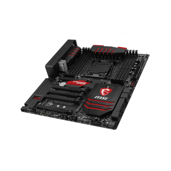
Chapter 1 Getting Started Thank you for choosing the X99S GAMING 9 AC Series (MS-7882 v1.X) EATX motherboard. The X99S GAMING 9 AC Series motherboards are based on Intel X99 chipset for optimal system efficiency. Designed to fit ® the advanced Intel LGA2011-3 processor, the X99S GAMING 9 AC Series ®... -
Page 16: Packing Contents
Packing Contents Drivers & Utilities Motherboard I/O Shield Motherboard Disc User Guide Wi-Fi/Bluetooth Software & Application V-Check Cable x6 SATA Cable x6 Driver Disc User Guide Wi-Fi/Bluetooth Antenna x2 SLI Cable x2 M-Connector module Audio Power eSATA Power eSATA Bracket eSATA Cable Adapter Cable... -
Page 17: Assembly Precautions
Assembly Precautions ■ The components included in this package are prone to damage from electrostatic discharge (ESD). Please adhere to the following instructions to ensure successful computer assembly. ■ Always turn off the power supply and unplug the power cord from the power outlet before installing or removing any computer component. -
Page 18: Motherboard Specifications
Motherboard Specifications ■ Supports New Intel Core™ i7 Processor Extreme Edition for ® LGA2011-3 Socket Support Chipset ■ Intel X99 Express Chipset ® Memory ■ 8x DDR4 memory slots supporting up to 128GB ■ Supports DDR4-2133/ 2200(OC)/ 2400(OC)/ 2600(OC)/ 2666(OC)/ Support 2750(OC) / 3000(OC)/ 3110(OC)/ 3333(OC) ■... - Page 19 ■ 1x Killer E2205 Gigabit LAN controller* * The Killer Network Manager is only available for Windows 7/ 8/ 8.1 currently. The support- ed drivers for other operating systems would be available on the website if provided by vender. Wireless ■...
- Page 20 BIOS ■ 2x 128 Mb flash ■ UEFI AMI BIOS Features ■ ACPI 5.0, PnP 1.0a, SM BIOS 2.7, DMI 2.0 ■ Multi-language Special ■ Streaming Engine ■ Audio Boost 2 Features ■ Military Class 4 ■ OC Genie 4 ■...
-
Page 21: Block Diagram
Block Diagram 4 Channel DDR4 Memory Haswell-E Processor LGA2011-3 CPU Switch Switch Streaming Engine PCI Express Bus (for 40 lanes CPU only) Switch PCI Express Bus Killer E2205 Gigabit LAN DMI 2.0 1 x M.2 Switch 1 x SATA Express Wi-Fi / Bluetooth 10 x SATA 6Gb/s... -
Page 22: Connectors Quick Guide
Connectors Quick Guide Wi-Fi/Bluetooth expansion BIOS1 module connector JPWR2 CPUFAN2 OC_SWITCH6 JPWR3 DIMM1 DIMM8 CPUFAN1 DIMM2 DIMM7 DIMM3 DIMM6 DIMM4 DIMM5 POWER1 Back RESET1 Panel JPWR1 SYSFAN3 JUSB3 PCI_E1 Streaming SATA1_2 Engine PCI_E2 SATA3_4 PCI_E3 SATA5_6_7_8 PCI_E4 M2_1 AUD_SW1 SATA9_10 PCI_E5 JCI1 JBAT1... - Page 23 Connectors Reference Guide Port Name Port Type Page AUDPWR1 Direct Audio Power Connector 1-29 AUD_SW1 Audio Power Switch 1-36 Back panel 1-10 BIOS1 Multi-BIOS Switch 1-35 LGA2011-3 Socket 1-12 CPUFAN1~2,SYSFAN1~3 Fan Power Connectors 1-25 DIMM1~8 Memory slots 1-16 V-Check Connectors 1-31 JAUD2 Front Panel Audio Connector...
-
Page 24: Back Panel Quick Guide
Back Panel Quick Guide LAN Port PS/2 Port* CS-Out Line-In/ SS-Out USB 3.0 Port USB 3.0 Port Clear CMOS RS-Out Line-Out Button USB 2.0 Port* USB 3.0 Port USB 3.0 Port Optical S/PDIF-Out * Gaming Device Port ▶ PS/2 Port A PS/2 DIN connector is for a PS/2 mouse/keyboard. - Page 25 ▶ LAN Port The standard RJ-45 LAN jack is for connecting to a Local Area Network (LAN). LED Status Description No link Link/ Activity LED Yellow Linked LINK/ACT SPEED Blinking Data activity 10 Mbps connection Speed LED Green 100 Mbps connection Orange 1 Gbps connection ▶...
-
Page 26: Cpu (Central Processing Unit)
CPU (Central Processing Unit) Introduction to the LGA2011-3 CPU The surface of the LGA2011-3 CPU has four alignment keys and a yellow triangle to assist in correctly lining up the CPU for motherboard placement. The yellow triangle is the Pin 1 indicator. Alignment Key Yellow triangle is the Pin 1 indicator... -
Page 27: Cpu & Heatsink Installation
CPU & Heatsink Installation When installing a CPU, always remember to install a CPU heatsink. A CPU heatsink is necessary to prevent overheating and maintain system stability. Follow the steps below to ensure correct CPU and heatsink installation. Wrong installation can damage both the CPU and the motherboard. - Page 28 5. Line up the CPU to fit the CPU socket. Be sure to hold the CPU by the base with the metal contacts facing downward. The alignment keys on the CPU will line up with the edges of the CPU socket to ensure a correct fit. 6.
- Page 29 9. Evenly spread a thin layer of thermal paste (or thermal tape) on the top of the CPU. This will help in heat dissipation and prevent CPU overheating. 10. Locate the CPU fan connector on the motherboard. CPUFAN1 Thermal paste 11.
-
Page 30: Memory
Memory These DIMM slots are used for installing memory modules. DIMM1 DIMM2 DIMM3 DIMM4 DIMM8 DIMM7 DIMM6 DIMM5 Video Demonstration Watch the video to learn how to install memory. http://youtu.be/T03aDrJPyQs Up to Quad-Channel mode This motherboard supports up to four memory channels. Two DIMM slots provide a single channel. -
Page 31: Suggestions For Multi-Channel Mode Population Rule
Suggestions for Multi-Channel mode population rule Dual-Channel mode Installed DIMMs Diagram (2 memory modules) DIMM1 DIMM2 DIMM3 DIMM4 DIMM1, DIMM5 DIMM8 DIMM7 DIMM6 DIMM5 Triple-Channel mode Installed DIMMs Diagram (3 memory modules) DIMM1 DIMM2 DIMM3 DIMM4 DIMM1, DIMM3, DIMM5 DIMM8 DIMM7 DIMM6 DIMM5... - Page 32 Quad-Channel mode Installed DIMMs Diagram (6 memory modules) DIMM1 DIMM2 DIMM3 DIMM4 DIMM1, DIMM2, DIMM3, DIMM5, DIMM6, DIMM7 DIMM8 DIMM7 DIMM6 DIMM5 Installed DIMMs Diagram (8 memory modules) DIMM1 DIMM2 DIMM3 DIMM1, DIMM2, DIMM4 DIMM3, DIMM4, DIMM5, DIMM6, DIMM8 DIMM7, DIMM8 DIMM7 DIMM6 DIMM5...
-
Page 33: Mounting Screw Holes
Mounting Screw Holes When installing the motherboard, first install the necessary mounting stands required for an motherboard on the mounting plate in your computer case. If there is an I/O back plate that came with the computer case, please replace it with the I/O backplate that came with the motherboard package. -
Page 34: Power Supply
Power Supply Video Demonstration Watch the video to learn how to install power supply connectors. http://youtu.be/gkDYyR_83I4 JPWR1~3: ATX Power Connectors These connectors allow you to connect an ATX power supply. To connect the ATX power supply, align the power supply cable with the connector and firmly press the cable into the connector. -
Page 35: Expansion Slots
Expansion Slots This motherboard contains numerous slots for expansion cards, such as discrete graphics or audio cards. PCI_E1~5: PCIe Expansion Slots The PCIe slot supports the PCIe interface expansion card. PCIe 3.0 x16 Slot PCIe Bandwidth Table ■ 3.0 = PCIe Gen 3.0 lanes, 2.0 = PCIe Gen 2.0 lanes Bandwidth 1-Way 2-Way... -
Page 36: Video/ Graphics Cards
Video/ Graphics Cards If available, this motherboard takes advantage of the CPU’s integrate graphics processor, but discrete video cards can be installed by way of the motherboard’s expansion slots. Adding on one or more discrete video cards will significantly boost the system’s graphics performance. -
Page 37: Internal Connectors
Internal Connectors SATA1~10: SATA Connectors This connector is a high-speed SATA interface port. Each connector can connect to one SATA device. SATA devices include disk drives (HDD), solid state drives (SSD), and optical drives (CD/ DVD/ Blu-Ray). Video Demonstration Watch the video to learn how to Install SATA HDD. http://youtu.be/RZsMpqxythc SATA2 SATA1... -
Page 38: Sata_Ex1: Sata Express Connector
SATA_EX1: SATA Express Connector The SATA Express, a new high performance storage interface, supports to connect 1 SATA Express device with up to 10 Gb/s transfer rate. Connects the SATA Express device to this 3-in-1 connector by a SATA Express cable. SATA Express M2_1: M.2 Port The M.2 port supports either M.2 SATA 6Gb/s module or M.2 PCIe module. -
Page 39: Cpufan1~2,Sysfan1~3: Fan Power Connectors
CPUFAN1~2,SYSFAN1~3: Fan Power Connectors The fan power connectors support system cooling fans with +12V. If the motherboard has a System Hardware Monitor chipset on-board, you must use a specially designed fan with a speed sensor to take advantage of the CPU fan control. Remember to connect all system fans. -
Page 40: Jfp1, Jfp2: System Panel Connectors
JFP1, JFP2: System Panel Connectors These connectors connect to the front panel switches and LEDs. The JFP1 connector is compliant with the Intel Front Panel I/O Connectivity Design Guide. When ® installing the front panel connectors, please use the optional M-Connector to simplify installation. -
Page 41: Jusb3~4: Usb 3.0 Expansion Connectors
JUSB3~4: USB 3.0 Expansion Connectors The USB 3.0 port is backwards compatible with USB 2.0 devices. It supports data transfer rates up to 5Gbits/s (SuperSpeed). The JUSB3 (red mark) connector supports MSI’s new Super-Charger technology which provides quicker USB charging of your smartphone or other USB-powered devices. -
Page 42: Jusb1~2: Usb 2.0 Expansion Connectors
JUSB1~2: USB 2.0 Expansion Connectors This connector is designed for connecting high-speed USB peripherals such as USB HDDs, digital cameras, MP3 players, printers, modems, and many others. Important Note that the VCC and GND pins must be connected correctly to avoid possible damage. -
Page 43: Jaud2: Front Panel Audio Connector
JAUD2: Front Panel Audio Connector This connector allows you to connect the front audio panel located on your computer case. This connector is compliant with the Intel Front Panel I/O Connectivity Design ® Guide. AUDPWR1: Direct Audio Power Connector This connector is used to provide direct power to back panel audio ports. The direct audio power can provide the better audio quality. -
Page 44: Jtpm1: Tpm Module Connector
JTPM1: TPM Module Connector This connector connects to a TPM (Trusted Platform Module). Please refer to the TPM security platform manual for more details and usages. Getting Started 1-30... -
Page 45: Voltage Checkpoints
Voltage Checkpoints These voltage checkpoints are used to measure the current system voltages. A multimeter (not included) will be required to check voltages. FV1: V-Check Connectors To check the voltage, please use the optional voltage checkpoint cables included in the motherboard package. Attach the positive lead of the multimeter to the voltage checkpoint cable and the negative lead to the ground connector. -
Page 46: Button
Button The motherboard has numerous on-board buttons to control various functions. This section will explain how to change your motherboard’s functions through the use of these on-board buttons. OC1: OC Genie Button This button is used to automatically overclock the system. To enable OC Genie, Set this button to ON while the system is in power off mode. -
Page 47: Power1: Power Button
POWER1: Power Button This button is used to turn-on and turn-off the system. Press the button once to turn-on or turn-off the system. RESET1: Reset Button This reset button is used to reset the system. Press the button to reset the system. 1-33 Getting Started... -
Page 48: Jumper
Jumper JBAT1: Clear CMOS Jumper There is CMOS RAM onboard that is external powered from a battery located on the motherboard to save system configuration data. With the CMOS RAM, the system can automatically boot into the operating system (OS) every time it is turned on. If you want to clear the system configuration, set the jumpers to clear the CMOS RAM. -
Page 49: Switch
Switch BIOS1: Multi-BIOS Switch This motherboard has two built-in BIOS ROMs (Labeled A and B, default BIOS ROM is A). If one is crashed, you can shift to the other for booting by sliding the switch. BIOS B BIOS A Blue LED Green LED BIOS recovery with AFUDOS command... -
Page 50: Oc_Switch6: Oc Genie Mode Switch
OC_SWITCH6: OC Genie Mode Switch This swtich provides two overclocking modes (Gear 1 and Gear 2) for OC Genie operation. When you press the OC Genie button, the overclocking procedure will be performed according to the setting of this switch. The Gear 1 Mode is the default setting. -
Page 51: Slow_1: Slow Mode Booting Switch
SLOW_1: Slow Mode Booting Switch This switch is used for LN2 cooling solution, that provides the extreme overclocking conditions, to boot at a stable processor frequency and to prevent the system from crashing. Normal Enabled (Default) (Please enable this swtich during BIOS POST.) Important •... -
Page 52: Led Status Indicators
LED Status Indicators OC Switch Gear 1 LED OC Switch Gear 2 LED Debug code LED BIOS A LED BIOS B LED LED Status Table The following table describes the status of LED indicators. LED Status Description OC Switch Gear 1 Blue Gear 1 OC Genie mode OC Switch Gear 2... -
Page 53: Debug Code Led Table
Debug Code LED Table Please refer to the table below to get more information about the Debug Code LED message. Post Status 02,07 Power on CPU Initialization 03,08 Power on North Bridge Initialization 04,09 Power on South Bridge Initialization Power on Cache Initialization 11~14,32~36,56~5A Early CPU Initialization 15~18,37~3A... -
Page 54: Drivers And Utilities
Drivers and Utilities After you install the operating system you will need to install drivers to maximize the performance of the new computer you just built. MSI motherboard comes with a Driver Disc. Drivers allow the computer to utilize your motherboard more efficiently and take advantage of any special features we provide. - Page 55 Chapter 2 Quick Installation This chapter provides demonstration diagrams about how to install your computer. Some of the installations also provide video demonstrations. Please link to the URL to watch it with the web browser on your phone or tablet. You may have even link to the URL by scanning the QR code. Important The diagrams in this chapter are for reference only and may vary from the product you purchased.
- Page 56 CPU Installation http://youtu.be/WPhyn2C5mgs Quick Installation...
-
Page 57: Chapter 2 Quick Installation
Quick Installation... -
Page 58: Memory Installation
Memory Installation http://youtu.be/T03aDrJPyQs Quick Installation... -
Page 59: Motherboard Installation
Motherboard Installation Quick Installation... - Page 60 Quick Installation...
-
Page 61: Power Connectors Installation
Power Connectors Installation http://youtu.be/gkDYyR_83I4 Quick Installation... - Page 62 Quick Installation...
-
Page 63: Sata Hdd Installation
SATA HDD Installation http://youtu.be/RZsMpqxythc Quick Installation... -
Page 64: M.2 Module Installation
M.2 module Installation http://youtu.be/JCTFABytrYA 30° Quick Installation 2-10... -
Page 65: Front Panel Connector Installation
Front Panel Connector Installation JFP1 Connector Installation http://youtu.be/DPELIdVNZUI Front Panel Audio Connector Installation 2-11 Quick Installation... -
Page 66: Peripheral Connector Installation
Peripheral Connector Installation USB2.0 Connector Installation USB3.0 Connector Installation Quick Installation 2-12... -
Page 67: Graphics Card Installation
Graphics Card Installation http://youtu.be/mG0GZpr9w_A 2-13 Quick Installation... - Page 68 Quick Installation 2-14...
-
Page 69: Chapter 3 Bios Setup
Chapter 3 BIOS Setup CLICK BIOS is a revolutionary UEFI interface that allows you to setup and configure your system for optimum use. Using your mouse and keyboard, users can change BIOS settings, monitor CPU temperature, select the boot device priority and view system information such as the CPU name, DRAM capacity, the OS version and the BIOS version. -
Page 70: Entering Setup
Entering Setup The default settings offer the optimal performance for system stability in normal conditions. You may need to run the Setup program when: ■ An error message appears on the screen during the system booting up, and requests you to run SETUP. ■... -
Page 71: Overview
Overview After entering BIOS, the following screen is displayed. Temperature monitor My Favorites Language System information Boot device priority bar Virtual OC Genie Button BIOS menu BIOS menu selection selection Menu display ▶ BIOS menu selection The following options are available: ■... - Page 72 ▶ Virtual OC Genie Button Enables or disables the OC Genie function by clicking on this button. When enabled, this button will be light. Enabling OC Genie function can automatically overclock with MSI optimized overclocking profile. Important We recommend that you do not to make any modification in OC menu mode and do not to load defaults after enabling the OC Genie function.
- Page 73 Adding BIOS item to Favorite 1~5 1. Move the mouse cursor to highlight a BIOS setting item. 2. Right-click (or press "F2" key) and then choose a favorite menu (Favorite 1~5) to add the BIOS item. Choose a favorite menu to add the BIOS item Deleting BIOS item from Favorite 1~5 1.
-
Page 74: Operation
Operation You can control BIOS settings with the mouse and the keyboard. The following table lists and describes the hot keys and the mouse operations. Hot key Mouse Description <↑↓→← > Select Item Move the cursor <Enter> Select Icon/ Field Click/ Double-click the left button <Esc>... -
Page 75: Updating Bios
Updating BIOS Updating the BIOS with M-FLASH ▶ Before updating Please download the latest BIOS file that matches your motherboard model from MSI website. And then save the BIOS file into the USB flash disk. Important Only the FAT32/ NTFS format USB flash disk supports updating BIOS by M-FLASH. ▶... -
Page 76: Settings
SETTINGS System Status ▶ System Date Sets the system date. Use tab key to switch between date elements. The format is <day> <month> <date> <year>. <day> Day of the week, from Sun to Sat, determined by BIOS. Read-only. <month> The month from Jan. through Dec. <date>... -
Page 77: Advanced
Advanced ▶ PCI Subsystem Settings Sets PCI, PCI express interface protocol and latency timer. Press <Enter> to enter the sub-menu. ▶ PEGX - Gen X [Auto] Sets PCI Express protocol for matching different installed devices. [Auto] Enables all PCIe Gen1, Gen2 and Gen3. supports. [Gen1] Enables PCIe Gen1 support only. - Page 78 ▶ sSATA Mode [AHCI Mode] (For SATA7~10) Sets the operation mode of the onboard 2nd SATA controller. [IDE Mode] Specify the IDE mode for SATA storage devices. [AHCI Mode] Specify the AHCI mode for SATA storage devices. AHCI (Advanced Host Controller Interface) offers some advanced features to enhance the speed and performance of SATA storage device, such as Native Command Queuing (NCQ) and hot-plugging.
- Page 79 ▶ EuP 2013 [Disabled] Enables or disables the system power consumption according to EuP 2013 regulation. [Enabled] Optimize the system power consumption according to EuP 2013 regulation. [Disabled] Disables this function. Note: When enabled, the system will not support S4 & S5 wake up by USB, PCI and PCIe devices.
- Page 80 ▶ Secure Boot Sets the Windows secure boot to prevent the unauthorized accessing. Press <Enter> to enter the sub-menu. This sub-menu will appear when “Windows 8/ 8.1 Feature” is enabled. ▶ Secure Boot Support [Disabled] Enables or disables secure boot support. [Enabled] Enables the secure boot function and allow you to set the secure boot settings.
-
Page 81: Boot
▶ Resume By USB Device [Disabled] Disables or enables the system wake up by USB devices. [Enabled] Enables the system to be awakened from sleep state when activity of USB device is detected. [Disabled] Disables this function. ▶ Resume From S3/S4/S5 by PS/2 Mouse [Disabled] Disables or enables the system wake up by PS/2 mouse. -
Page 82: Security
▶ Boot Option #1~N These items are used to prioritize the installed boot devices. Security ▶ Administrator Password Sets administrator password for system security. Enters the administrator password if set; user has full rights to change the BIOS items. ▶ User Password Sets User Password for system security. - Page 83 ▶ Restore Defaults This item is used to restore/ load all default values by the BIOS vendor. ▶ Boot Override The installed boot-able devices will appear on this menu, you can select one of them be a boot device to start booting. 3-15 BIOS Setup...
- Page 84 Important • Overclocking your PC manually is only recommended for advanced users. • Overclocking is not guaranteed, and if done improperly, can void your warranty or severely damage your hardware. • If you are unfamiliar with overclocking, we advise you to use OC Genie for easy overclocking.
- Page 85 ▶ Adjusted CPU Frequency Shows the adjusted CPU frequency. Read-only. ▶ CPU Ratio Mode [Dynamic Mode]* Selects the CPU Ratio operating mode. This item will appear when you set the CPU ratio manually. [Fixed Mode] Fixes the CPU ratio. [Dynamic Mode] CPU ratio will be changed dynamically according to the CPU loading.
- Page 86 ▶ CPU Base Clock Apply Mode [Auto]* Sets the applying mode for adjusted CPU base clock. [Auto] This setting will be configured automatically by BIOS. [Next Boot] CPU will run the adjusted CPU base clock at next boot. [Immediate] CPU runs the adjusted CPU base clock immediately. [During Boot] CPU will run the adjusted CPU base clock during boot.
- Page 87 ▶ Memory Fast Boot [Auto] Enables or disables the initiation and training for memory every booting. [Auto] This setting will be configured automatically by BIOS. [Enabled] Memory will completely imitate the archive of first initiation and first training. After that, the memory will not be initialed and trained when booting to accelerate the system booting time.
- Page 88 ▶ CPU VRM Over Temperature Protection [Enabled] Enables or disables the CPU VRM over-temperature protection. [Enabled] Sets the temperature limit on CPU VRM for over-temperature protection. The CPU frequency may be throttled when CPU temperature over the specified temperature. [Disabled] Disables this function.
- Page 89 ▶ CPU Core/Ring Voltage Mode [Auto]* Selects the control mode for CPU Core/ Ring voltages. [Auto] This setting will be configured automatically by BIOS. [Adaptive Mode] Sets the adaptive voltage automatically for optimizing the system performance. [Override Mode] Allows you to set the voltage manually. [Offset Mode] Allows you to set the offset voltage and select the voltage offset mode.
- Page 90 ▶ XXX Voltage [Auto]* (optional) Sets the voltages related to memory/ PCH. If set to "Auto", BIOS will set the voltage automatically or you can set it manually. < Other Setting > ▶ CPU Memory Changed Detect [Enabled]* Enables or disables the system to issue a warning message during boot when the CPU or memory has been replaced.
- Page 91 ▶ Execute Disable Bit [Enabled] Intel’s Execute Disable Bit functionality can prevent certain classes of malicious “buffer overflow” attacks where worms attempt to execute code to damage the system. It is recommended that keeps this item enabled always. [Enabled] Enables NO-Execution protection to prevent the malicious attacks and worms.
- Page 92 ▶ Intel C-State [Enabled] C-state is a processor power management technology defined by ACPI. [Auto] This setting will be configured automatically by BIOS. [Enabled] Detects the idle state of system and reduce CPU power consumption accordingly. [Disabled] Disable this function. ▶...
- Page 93 ▶ Internal VR OVP OCP Protection [Auto] Enables or disables the over-voltage protection and over-current protection for CPU internal VR (Voltage Regulator). [Auto] This setting will be configured automatically by BIOS. [Enabled] Enables the limitation of internal VR for over-voltage protection and over-current protection.
-
Page 94: M-Flash
M-FLASH Important M-Flash funcion allows you to update BIOS from USB flash disk (FAT32/ NTFS format only), or allows the system to boot from the BIOS file inside USB flash disk (FAT/ FAT32 format only). ▶ BIOS Boot Function [Disabled] Enables or disables the system to boot form USB flash disk with BIOS file. -
Page 95: Oc Profile
OC PROFILE ▶ Overclocking Profile 1/ 2/ 3/ 4/ 5/ 6 Overclocking Profile 1/ 2/ 3/ 4/ 5/ 6 management. Press <Enter> to enter the sub- menu. ▶ Set Name for Overclocking Profile 1/ 2/ 3/ 4/ 5/ 6 Names the current overclocking profile. ▶... -
Page 96: Hardware Monitor
HARDWARE MONITOR Current Temperature & Speed information control field Setting Buttons Voltage display ▶ Current Temperature & Speed information Shows the current CPU temperature, system temperature and fans' speeds. ▶ Fan control field This motherboard provides a fan speed control feature call “Smart Fan Mode”. Please check the “Smart Fan Mode”... -
Page 97: Appendix A Realtek Audio
Appendix A Realtek Audio The Realtek audio provides 10-channel DAC that simultaneously supports 7.1 sound playback and 2 channels of independent stereo sound output (multiple streaming) through the Front-Out-Left and Front-Out-Right channels. -
Page 98: Software Configuration
Software Configuration After installing the audio driver (see Chapter 1 - Driver and Utilities), the “Realtek HD Audio Manager” icon will appear at the notification area (lower right of the screen). You may double click the icon and the GUI will pop up accordingly. double click the icon It is also available to enable the audio driver by clicking the Realtek HD Audio Manager from the Control Panel. -
Page 99: Auto Popup Dialog
▶ Device Selection Here you can select a audio output source to change the related options. The “check” sign indicates the devices as default. ▶ Volume Adjustment You can control the volume or balance the right/left side of the speakers that you plugged in front or rear panel by adjust the bar. -
Page 101: Appendix B Intel Raid
Appendix B Intel RAID This appendix will assist users in configuring and enabling RAID functionality and accelerating system on platforms... -
Page 102: Introduction
Introduction The motherboard comes with the Intel RAID controller that allows you to configure SATA hard drives as RAID sets. SATA hard drives deliver blistering transfer speeds up to 6 Gb/s. Serial ATA uses long, thin cables, making it easier to connect your drive and improving the airflow inside your PC. -
Page 103: Using Intel Rapid Storage Technology Option Rom
Using Intel Rapid Storage Technology Option ROM The Intel Rapid Storage Technology Option ROM should be integrated with the system BIOS on all motherboards with a supported Intel chipset. The Intel Rapid Storage Technology Option ROM is the Intel RAID implementation and provides BIOS and DOS disk services. -
Page 104: Create Raid Volume
After pressing the <Ctrl> and <I> keys simultaneously, the following window will appear: MAIN MENU MAIN MENU Create RAID Volume Recovery Volume Options Acceleration Options Delete RAID Volume Exit Reset Disks to Non-RAID DISK / VOLUME INFORMATION RAID Volumes : None defined. - Page 105 3. In the Disk field, press <Enter> key and use <Space> key to select the disks you want to create for the RAID volume, then click <Enter> key to finish selection. This field will become available according to the selected RAID level. 4.
-
Page 106: Intel Raid
6. Go to the Create Volume field and press <Enter>, the following screen appears for you to confirm if you are sure to create the RAID volume. Press <Y> to continue. CREATE VOLUME MENU Name : Volume0 RAID Level : RAID1(Mirror) Disks : Select Disks... -
Page 107: Delete Raid Volume
■ Delete RAID Volume Here you can delete the RAID volume, but please be noted that all data on RAID drives will be lost. Important If your system currently boots to RAID and you delete the RAID volume in the Intel RAID Option ROM, your system will become un-bootable. - Page 108 ■ Reset Disks to Non-RAID Select option 3 Reset Disks to Non-RAID and press <Enter> to delete the RAID volume and remove any RAID structures from the drives. The following screen appears: MAIN MENU Recovery Volume Options Create RAID Volume RESET RAID DATA Recovery Volume Options Delete RAID Volume...
-
Page 109: Recovery Volume Options
■ Recovery Volume Options Select option 4 Recovery Volume Options and press <Enter> to change recovery volume mode. The following screen appears: RECOVERY VOLUME OPTIONS Enable Only Recovery Disk Enable Only Master Disk HELP Enable Only Recovery Disk - enables recovery disk if available and disables master disk. -
Page 110: Degraded Raid Array
Degraded RAID Array A RAID 1, RAID 5 or RAID 10 volume is reported as degraded when one of its hard drive members fails or is temporarily disconnected, and data mirroring is lost. As a result, the system can only utilize the remaining functional hard drive member. To re-establish data mirroring and restore data redundancy, refer to the procedure below that corresponds to the current situation. - Page 111 5. Exit Intel RAID Option ROM, and then reboot to Windows system. 6. When prompted to rebuild the RAID volume, click ‘Yes’. 7. The Intel Rapid Storage Technology application will be launched. Right-click the new hard drive and select ‘Rebuild to this Disk’. The ‘Rebuild Wizard’ will be launched which will guide you through the process of rebuilding to the new hard drive.
-
Page 112: System Acceleration (Optional
System Acceleration (optional) Intel Rapid Storage Technology use a SSD as a cache. Which can store frequently ® used data without having to use a slow virtual disk or depend on RAM. The SSD cache with the advantages of high-speed read/write and non-volatile memory to accelerate the system performance. - Page 113 9. Run Intel Rapid Storage Technology application. 10. Click "Enable acceleration" under Performance tab. Click here 11. Select the acceleration mode options. 12. Click OK and reboot the system. The page refreshes and reports the new acceleration configuration in the Acceleration View.
-
Page 114: Rst Synchronization (Optional
RST Synchronization (optional) If you are using Maximized mode as the Acceleration mode, the data on the hard disk is not always synchronized with the data in the SSD cache. In some situations, you may want to manually sync the disks for avoiding data loss. Follow these steps to sync manually.
Need help?
Do you have a question about the X99S GAMING 9 AC and is the answer not in the manual?
Questions and answers