Table of Contents
Advertisement
Advertisement
Table of Contents

Related Manuals for MSI X99A RAIDER


Summary of Contents for MSI X99A RAIDER
- Page 1 Preface X99A RAIDER Motherboard G52-78851XK...
-
Page 2: Preface
Copyright Notice The material in this document is the intellectual property of MICRO-STAR INTERNATIONAL. We take every care in the preparation of this document, but no guarantee is given as to the correctness of its contents. Our products are under continual improvement and we reserve the right to make changes without notice. -
Page 3: Smartphone Application
If a problem arises with your system and no solution can be obtained from the user’s manual, please contact your place of purchase or local distributor. Alternatively, please try the following help resources for further guidance. Visit the MSI website for technical guide, BIOS updates, driver updates, and other information: http://www.msi.com/service/download/ Contact our technical staff at: http://register.msi.com/... -
Page 4: Safety Instructions
Safety Instructions ■ Always read the safety instructions carefully. ■ Keep this User’s Manual for future reference. ■ Keep this equipment away from humidity. ■ Lay this equipment on a reliable flat surface before setting it up. ■ The openings on the enclosure are for air convection hence protects the equipment from overheating. -
Page 5: Fcc-B Radio Frequency Interference Statement
FCC-B Radio Frequency Interference Statement This equipment has been tested and found to comply with the limits for a Class B digital device, pursuant to Part 15 of the FCC Rules. These limits are designed to provide reasonable protection against harmful interference in a residential installation. This equipment generates, uses and can radiate radio frequency energy and, if not installed and used in accordance with the instructions, may cause harmful interference to radio communications. -
Page 6: Radiation Exposure Statement
Radiation Exposure Statement This equipment complies with FCC radiation exposure limits set forth for an uncontrolled environment. This equipment and its antenna should be installed and operated with minimum distance 20 cm between the radiator and your body. This equipment and its antenna must not be co-located or operating in conjunction with any other antenna or transmitter. -
Page 7: Battery Information
Replace only with the same or equivalent type recommended by the manufacturer. Chemical Substances Information In compliance with chemical substances regulations, such as the EU REACH Regulation (Regulation EC No. 1907/2006 of the European Parliament and the Council), MSI provides the information of chemical substances in products at: http://www.msi.com/html/popup/csr/evmtprtt_pcm.html Preface... -
Page 8: Weee (Waste Electrical And Electronic Equipment) Statement
MSI will comply with the product take back requirements at the end of life of MSI-branded products that are sold into the EU. You can return these products to local collection points. - Page 9 MSI će poštovati zahtev o preuzimanju ovakvih proizvoda kojima je istekao vek trajanja, koji imaju MSI oznaku i koji su prodati u EU. Ove proizvode možete vratiti na lokalnim mestima za prikupljanje.
- Page 10 MSI si adeguerà a tale Direttiva ritirando tutti i prodotti marchiati MSI che sono stati venduti all’interno dell’Unione Europea alla fine del loro ciclo di vita.
-
Page 11: 日本Jis C 0950材質宣言
2008 № 1057. Việt Nam RoHS Kể từ ngày 01/12/2012, tất cả các sản phẩm do công ty MSI sản xuất tuân thủ Thông tư số 30/2011/TT-BCT quy định tạm thời về giới hạn hàm lượng cho phép của một số... -
Page 12: Table Of Contents
CONTENTS ▍ Preface ......................i Copyright Notice .......................ii Trademarks ......................ii Revision History .......................ii Smartphone Application ..................iii Technical Support ....................iii Safety Instructions ....................iv FCC-B Radio Frequency Interference Statement ........... v CE Conformity ......................v Radiation Exposure Statement ................vi European Community Compliance Statement ............vi Taiwan Wireless Statements ...................vi Japan VCCI Class B Statement ................vi Korea Warning Statements ..................vi... - Page 13 Quad-Channel mode ................... 1-18 Mounting Screw Holes ..................1-19 Power Supply ..................... 1-20 JPWR1~2: ATX Power Connectors ............. 1-20 Expansion Slots ....................1-21 PCI_E1~5: PCIe Expansion Slots ..............1-21 PCIe Bandwidth Table ................1-21 Video/ Graphics Cards ..................1-22 Single Video Card Installation ..............1-22 Internal Connectors ....................
- Page 14 Chapter 3 BIOS Setup .................3-1 Entering Setup ..................... 3-2 Entering BIOS Setup ..................3-2 Overview ......................3-3 Operation ......................3-6 Updating BIOS ..................... 3-7 Updating the BIOS with M-FLASH ..............3-7 SETTINGS ......................3-8 System Status ....................3-8 Advanced ....................... 3-9 Boot ......................
-
Page 15: Chapter 1 Getting Started
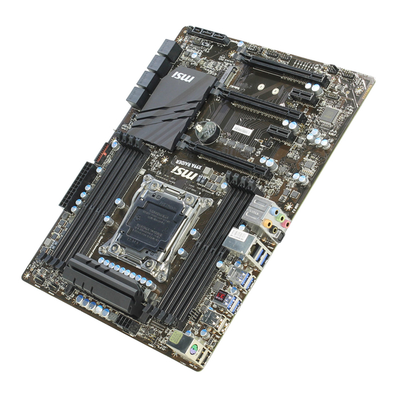
Chapter 1 Getting Started Thank you for choosing the X99A RAIDER Series (MS-7885 v5.X) ATX motherboard. The X99A RAIDER Series motherboards are based on Intel ® X99 chipset for optimal system efficiency. Designed to fit the advanced Intel ® LGA2011-3 processor, the X99A RAIDER Series motherboards deliver a high... -
Page 16: Packing Contents
Packing Contents Drivers & Utilities Motherboard I/O Shield Motherboard Disc User Guide SLI Cable M-Connector SATA Cable * These pictures are for reference only and may vary without notice. * The packing contents may vary according to the model you purchased. Getting Started... -
Page 17: Assembly Precautions
Assembly Precautions ■ The components included in this package are prone to damage from electrostatic discharge (ESD). Please adhere to the following instructions to ensure successful computer assembly. ■ Always turn off the power supply and unplug the power cord from the power outlet before installing or removing any computer component. -
Page 18: Motherboard Specifications
- 6x USB 2.0 ports (4 ports on the back panel, 2 ports available through the internal USB 2.0 connectors) ■ ASMedia ASM1142 - 2x USB 3.1 ports on the back panel * Internal JUSB1 connector supports MSI Super Charger. Audio ■ Realtek ALC892 Codec ®... - Page 19 Back Panel ■ 1x PS/2 keyboard/ mouse combo port ■ 4x USB 2.0 ports Connectors ■ 1x Clear CMOS button ■ 4x USB 3.0 ports ■ 2x USB 3.1 ports ■ 1x LAN (RJ45) port ■ 1x Optical S/PDIF OUT connector ■...
- Page 20 Software ■ Drivers ■ MSI - Command Center - Live Update 6 - Smart Utilities - Super Charger - Fast Boot - ECO Center ■ Norton Internet Security Solution ■ Intel Extreme Tuning Utility Form ■ ATX Form Factor ■ 12 in. x 9.6 in. (30.5 cm x 24.4 cm)
-
Page 21: Block Diagram
Block Diagram 4 Channel DDR4 Memory Haswell-E Processor LGA2011-3 CPU PCIe x1 slot PCI Express Bus PCI Express Bus Intel I218 Gigabit LAN DMI 2.0 1 x M.2 Switch 1 x SATA Express PCIe x1 slot 10 x SATA 6Gb/s (2 ports reserved for SATA Express) X99 PCH 6 x USB 3.0... -
Page 22: Connectors Quick Guide
Connectors Quick Guide JPWR2 CPUFAN2 DIMM1 DIMM8 SYSFAN1 DIMM2 DIMM7 DIMM3 DIMM6 CPU Socket DIMM4 DIMM5 CPUFAN1 Back Panel JPWR1 JUSB1 PCI_E1 JBAT1 SATA1_2 PCI_E2 SATA3_4 PCI_E3 SATA7_8 M2_1 PCI_E4 SATA9_10 JTPM1 PCI_E5 BIOS1 SYSFAN2 JAUD1 SYSFAN3 SATA6 SATA5 JSLOW1 JUSB2 JCI1 JFP1... - Page 23 Connectors Reference Guide Port Name Port Type Page Back Panel 1-10 BIOS1 Multi-BIOS Switch 1-31 CPUFAN1~2,SYSFAN1~3 Fan Power Connectors 1-25 DIMM1~8 Memory Slots 1-16 JAUD1 Front Panel Audio Connector 1-29 JBAT1 Clear CMOS Jumper 1-30 JCI1 Chassis Intrusion Connector 1-28 JFP1, JFP2 System Panel Connectors 1-26...
-
Page 24: Back Panel Quick Guide
Back Panel Quick Guide LAN Port PS/2 Port CS-Out Line-In/ SS-Out USB 2.0 Port USB 3.0 Port Clear CMOS RS-Out Line-Out Button USB 2.0 Port USB 3.1 Port USB 3.0 Port Optical S/PDIF-Out ▶ PS/2 Port A PS/2 DIN connector is for a PS/2 mouse/keyboard. - Page 25 ▶ LAN Port The standard RJ-45 LAN jack is for connecting to a Local Area Network (LAN). LED Status Description No link Link/ Activity LED Yellow Linked LINK/ACT SPEED Blinking Data activity 10 Mbps connection Speed LED Green 100 Mbps connection Orange 1 Gbps connection ▶...
-
Page 26: Cpu (Central Processing Unit)
This motherboard is designed to support overclocking. Before attempting to overclock, please make sure that all other system components can tolerate overclocking. Any attempt to operate beyond product specifications is not recommend. MSI does not guarantee the damages or risks caused by inadequate operation beyond product specifications. -
Page 27: Cpu & Heatsink Installation
CPU & Heatsink Installation When installing a CPU, always remember to install a CPU heatsink. A CPU heatsink is necessary to prevent overheating and maintain system stability. Follow the steps below to ensure correct CPU and heatsink installation. Wrong installation can damage both the CPU and the motherboard. - Page 28 5. Line up the CPU to fit the CPU socket. Be sure to hold the CPU by the base with the metal contacts facing downward. The alignment keys on the CPU will line up with the edges of the CPU socket to ensure a correct fit. 6.
- Page 29 9. Evenly spread a thin layer of thermal paste (or thermal tape) on the top of the CPU. This will help in heat dissipation and prevent CPU overheating. 10. Locate the CPU fan connector on the mainboard. CPUFAN1 Thermal paste 11.
-
Page 30: Memory
Memory These DIMM slots are used for installing memory modules. DIMM1 DIMM2 DIMM3 DIMM4 DIMM8 DIMM7 DIMM6 DIMM5 Video Demonstration Watch the video to learn how to install memory. http://youtu.be/T03aDrJPyQs Up to Quad-Channel mode This mainboard supports up to four memory channels. Two DIMM slots provide a single channel. -
Page 31: Suggestions For Multi-Channel Mode Population Rule
Suggestions for Multi-Channel mode population rule Dual-Channel mode Installed DIMMs Diagram (2 memory modules) DIMM1 DIMM2 DIMM3 DIMM4 DIMM1, DIMM5 DIMM8 DIMM7 DIMM6 DIMM5 Triple-Channel mode Installed DIMMs Diagram (3 memory modules) DIMM1 DIMM2 DIMM3 DIMM4 DIMM1, DIMM3, DIMM5 DIMM8 DIMM7 DIMM6 DIMM5... -
Page 32: Quad-Channel Mode
Quad-Channel mode Installed DIMMs Diagram (6 memory modules) DIMM1 DIMM2 DIMM3 DIMM4 DIMM1, DIMM2, DIMM3, DIMM5, DIMM6, DIMM7 DIMM8 DIMM7 DIMM6 DIMM5 Installed DIMMs Diagram (8 memory modules) DIMM1 DIMM2 DIMM3 DIMM1, DIMM2, DIMM4 DIMM3, DIMM4, DIMM5, DIMM6, DIMM8 DIMM7, DIMM8 DIMM7 DIMM6 DIMM5... -
Page 33: Mounting Screw Holes
Mounting Screw Holes When installing the motherboard, first install the necessary mounting stands required for an motherboard on the mounting plate in your computer case. If there is an I/O back plate that came with the computer case, please replace it with the I/O backplate that came with the motherboard package. -
Page 34: Power Supply
Power Supply Video Demonstration Watch the video to learn how to install power supply connectors. http://youtu.be/gkDYyR_83I4 JPWR1~2: ATX Power Connectors These connectors allow you to connect an ATX power supply. To connect the ATX power supply, align the power supply cable with the connector and firmly press the cable into the connector. -
Page 35: Expansion Slots
Expansion Slots This motherboard contains numerous slots for expansion cards, such as discrete graphics or audio cards. PCI_E1~5: PCIe Expansion Slots The PCIe slot supports the PCIe interface expansion card. PCIe 3.0 x16 Slot PCIe 2.0 x1 Slot PCIe Bandwidth Table ■... -
Page 36: Video/ Graphics Cards
Adding on one or more discrete video cards will significantly boost the system’s graphics performance. For best compatibility, MSI graphics cards are recommended. Video Demonstration Watch the video to learn how to install a graphics card on PCIe x16 slot with butterfly lock. -
Page 37: Internal Connectors
Internal Connectors SATA1~10: SATA Connectors This connector is a high-speed SATA interface port. Each connector can connect to one SATA device. SATA devices include disk drives (HDD), solid state drives (SSD), and optical drives (CD/ DVD/ Blu-Ray). Video Demonstration Watch the video to learn how to Install SATA HDD. http://youtu.be/RZsMpqxythc SATA2 SATA1... -
Page 38: Sata_Ex1: Sata Express Connector
SATA_EX1: SATA Express Connector The SATA Express, a new high performance storage interface, supports to connect 1 SATA Express device with up to 10 Gb/s transfer rate. Connects the SATA Express device to this 3-in-1 connector by a SATA Express cable. M2_1: M.2 Port The M.2 port supports either M.2 SATA 6Gb/s module or M.2 PCIe module. -
Page 39: Cpufan1~2,Sysfan1~3: Fan Power Connectors
CPUFAN1~2,SYSFAN1~3: Fan Power Connectors The fan power connectors support system cooling fans with +12V. If the motherboard has a System Hardware Monitor chipset on-board, you must use a specially designed fan with a speed sensor to take advantage of the CPU fan control. Remember to connect all system fans. -
Page 40: Jfp1, Jfp2: System Panel Connectors
JFP1, JFP2: System Panel Connectors These connectors connect to the front panel switches and LEDs. The JFP1 connector is compliant with the Intel Front Panel I/O Connectivity Design Guide. When ® installing the front panel connectors, please use the optional M-Connector to simplify installation. -
Page 41: Jusb1: Usb 3.0 Expansion Connector
• Please only connect one device per USB port to ensure stable charging. • Super-Charger Technology is only available on select MSI motherboard models. Please refer to the MSI website to check if your motherboard has Super-Charger technology. • For iPad, JUSB1 (red mark) can still charge iPad in S3, S4, S5 state. -
Page 42: Jusb2: Usb 2.0 Expansion Connector
JUSB2: USB 2.0 Expansion Connector This connector is designed for connecting high-speed USB peripherals such as USB HDDs, digital cameras, MP3 players, printers, modems, and many others. Important Note that the VCC and GND pins must be connected correctly to avoid possible damage. -
Page 43: Jaud1: Front Panel Audio Connector
JAUD1: Front Panel Audio Connector This connector allows you to connect the front audio panel located on your computer case. This connector is compliant with the Intel Front Panel I/O Connectivity Design ® Guide. JTPM1: TPM Module Connector This connector connects to a TPM (Trusted Platform Module). Please refer to the TPM security platform manual for more details and usages. -
Page 44: Jumper
Jumper JBAT1: Clear CMOS Jumper There is CMOS RAM onboard that is external powered from a battery located on the motherboard to save system configuration data. With the CMOS RAM, the system can automatically boot into the operating system (OS) every time it is turned on. If you want to clear the system configuration, set the jumpers to clear the CMOS RAM. -
Page 45: Switch
Preparation: 1. Prepare a bootable USB flash drive. 2. Download the latest BIOS file from the MSI official website at www.msi.com, and then decompress the file. 3. Copy the AFUDE238.exe and the BIOS file to the bootable USB flash drive BIOS recovery steps: 1. -
Page 46: Drivers And Utilities
After you install the operating system you will need to install drivers to maximize the performance of the new computer you just built. MSI motherboard comes with a Driver Disc. Drivers allow the computer to utilize your motherboard more efficiently and take advantage of any special features we provide. - Page 47 Chapter 2 Quick Installation This chapter provides demonstration diagrams about how to install your computer. Some of the installations also provide video demonstrations. Please link to the URL to watch it with the web browser on your phone or tablet. You may have even link to the URL by scanning the QR code. Important The diagrams in this chapter are for reference only and may vary from the product you purchased.
- Page 48 CPU Installation http://youtu.be/WPhyn2C5mgs Quick Installation...
-
Page 49: Chapter 2 Quick Installation
Quick Installation... -
Page 50: Memory Installation
Memory Installation http://youtu.be/T03aDrJPyQs Quick Installation... -
Page 51: Motherboard Installation
Motherboard Installation Quick Installation... - Page 52 Quick Installation...
-
Page 53: Power Connectors Installation
Power Connectors Installation http://youtu.be/gkDYyR_83I4 Quick Installation... - Page 54 Quick Installation...
-
Page 55: Sata Hdd Installation
SATA HDD Installation http://youtu.be/RZsMpqxythc Quick Installation... -
Page 56: M.2 Module Installation
M.2 module Installation http://youtu.be/JCTFABytrYA 30° Quick Installation 2-10... -
Page 57: Front Panel Connector Installation
Front Panel Connector Installation JFP1 Connector Installation http://youtu.be/DPELIdVNZUI Front Panel Audio Connector Installation 2-11 Quick Installation... -
Page 58: Peripheral Connector Installation
Peripheral Connector Installation USB2.0 Connector Installation USB3.0 Connector Installation Quick Installation 2-12... -
Page 59: Graphics Card Installation
Graphics Card Installation http://youtu.be/mG0GZpr9w_A 2-13 Quick Installation... - Page 60 Quick Installation 2-14...
-
Page 61: Chapter 3 Bios Setup
Chapter 3 BIOS Setup CLICK BIOS is a revolutionary UEFI interface that allows you to setup and configure your system for optimum use. Using your mouse and keyboard, users can change BIOS settings, monitor CPU temperature, select the boot device priority and view system information such as the CPU name, DRAM capacity, the OS version and the BIOS version. -
Page 62: Entering Setup
(optional) on the motherboard to enable the system going to BIOS setup directly at next boot. Click "GO2BIOS" tab on "MSI Fast Boot" utility screen. Important Please be sure to install the “MSI Fast Boot” utility before using it to enter the BIOS setup. BIOS Setup... -
Page 63: Overview
Overview After entering BIOS, the following screen is displayed. Temperature monitor My Favorites Language System XMP Button information Boot device priority bar Virtual OC Genie Button BIOS menu BIOS menu selection selection Menu display ▶ BIOS menu selection The following options are available: ■... - Page 64 Enables or disables the OC Genie function by clicking on this button. When enabled, this button will be light. Enabling OC Genie function can automatically overclock with MSI optimized overclocking profile. Important We recommend that you do not to make any modification in OC menu mode and do not to load defaults after enabling the OC Genie function.
- Page 65 Adding BIOS item to Favorite 1~5 1. Move the mouse cursor to highlight a BIOS setting item. 2. Right-click (or press "F2" key) and then choose a favorite menu (Favorite 1~5) to add the BIOS item. Choose a favorite menu to add the BIOS item Deleting BIOS item from Favorite 1~5 1.
-
Page 66: Operation
Operation You can control BIOS settings with the mouse and the keyboard. The following table lists and describes the hot keys and the mouse operations. Hot key Mouse Description <↑↓→← > Select Item Move the cursor <Enter> Select Icon/ Field Click/ Double-click the left button <Esc>... -
Page 67: Updating Bios
Updating BIOS Updating the BIOS with M-FLASH ▶ Before updating Please download the latest BIOS file that matches your motherboard model from MSI website. And then save the BIOS file into the USB flash disk. Important Only the FAT32/ NTFS format USB flash disk supports updating BIOS by M-FLASH. -
Page 68: Settings
SETTINGS System Status ▶ System Date Sets the system date. Use tab key to switch between date elements. The format is <day> <month> <date> <year>. <day> Day of the week, from Sun to Sat, determined by BIOS. Read-only. <month> The month from Jan. through Dec. <date>... -
Page 69: Advanced
Advanced ▶ PCI Subsystem Settings Sets PCI, PCI express interface protocol and latency timer. Press <Enter> to enter the sub-menu. ▶ PEGX - Gen X [Auto] Sets PCI Express protocol for matching different installed devices. [Auto] Enables all PCIe Gen1, Gen2 and Gen3. supports. [Gen1] Enables PCIe Gen1 support only. - Page 70 ▶ sSATA Mode [AHCI Mode] (For SATA7~10) Sets the operation mode of the onboard 2nd SATA controller. [IDE Mode] Specify the IDE mode for SATA storage devices. [AHCI Mode] Specify the AHCI mode for SATA storage devices. AHCI (Advanced Host Controller Interface) offers some advanced features to enhance the speed and performance of SATA storage device, such as Native Command Queuing (NCQ) and hot-plugging.
- Page 71 Disables this function. ▶ MSI Fast Boot [Disabled] MSI Fast Boot is the fastest way to boot the system. It will disable more devices to speed up system boot time which is faster than the boot time of “Fast Boot”.
- Page 72 ▶ Secure Boot Sets the Windows secure boot to prevent the unauthorized accessing. Press <Enter> to enter the sub-menu. This sub-menu will appear when “Windows 8/ 8.1 Feature” is enabled. ▶ Secure Boot Support [Disabled] Enables or disables secure boot support. [Enabled] Enables the secure boot function and allow you to set the secure boot settings.
-
Page 73: Boot
▶ Resume By Onboard LAN [Disabled] Disables or enables the system wake up by Onboard LAN. [Enabled] Enables the system to be awakened from the power saving modes when activity or input signal of LAN device is detected. [Disabled] Disables this function. ▶... -
Page 74: Security
Security ▶ Administrator Password Sets administrator password for system security. Enters the administrator password if set; user has full rights to change the BIOS items. ▶ User Password Sets User Password for system security. Enters the user password if set; but user might have limited rights to change the BIOS items. -
Page 75: Save & Exit
Save & Exit ▶ Discard Changes and Exit Exit BIOS setup without saving any change. This it is used to abandon all changes and exit BIOS setup. ▶ Save Changes and Reboot This item is used to save all changes and reboot the system. ▶... - Page 76 Important • Overclocking your PC manually is only recommended for advanced users. • Overclocking is not guaranteed, and if done improperly, can void your warranty or severely damage your hardware. • If you are unfamiliar with overclocking, we advise you to use OC Genie for easy overclocking.
- Page 77 ▶ Adjusted CPU Frequency Shows the adjusted CPU frequency. Read-only. ▶ CPU Ratio Mode [Dynamic Mode]* Selects the CPU Ratio operating mode. This item will appear when you set the CPU ratio manually. [Fixed Mode] Fixes the CPU ratio. [Dynamic Mode] CPU ratio will be changed dynamically according to the CPU loading.
- Page 78 ▶ CPU Base Clock Apply Mode [Auto]* Sets the applying mode for adjusted CPU base clock. [Auto] This setting will be configured automatically by BIOS. [Next Boot] CPU will run the adjusted CPU base clock at next boot. [Immediate] CPU runs the adjusted CPU base clock immediately. [During Boot] CPU will run the adjusted CPU base clock during boot.
- Page 79 ▶ Memory Fast Boot [Auto] Enables or disables the initiation and training for memory every booting. [Auto] This setting will be configured automatically by BIOS. [Enabled] Memory will completely imitate the archive of first initiation and first training. After that, the memory will not be initialed and trained when booting to accelerate the system booting time.
- Page 80 ▶ CPU Over Temperature Protection [Enabled] Enables or disables the CPU over-temperature protection. [Enabled] Sets the temperature limit on CPU for over-temperature protection. The CPU frequency may be throttled when CPU temperature over the specified temperature. [Disabled] Disables this function. ▶...
- Page 81 ▶ SVID Communication [Auto]* Enables or disables SVID (Serial Voltage Identification) support. [Auto] This setting will be configured automatically by BIOS. [Enabled] PWM phase will be changed dynamically according to the CPU SVID (Serial Voltage Identification). [Disabled] Disables SVID (Serial Voltage Identification) support. ▶...
- Page 82 ▶ CPU SA Voltage Offset [Auto]* Sets the offset value of CPU SA voltage. If set to "Auto", BIOS will set these voltages automatically or you can set it manually. This item appears when “CPU SA/IOA/IOD Voltage Mode” sets to [Offset Mode]. ▶...
- Page 83 ▶ Core0~X [Enabled] Enables or disables the CPU core. These items only appear when “Active Processor Cores Control” is enabled. ▶ Limit CPUID Maximum [Disabled] Enables or disables the extended CPUID value. [Enabled] BIOS will limit the maximum CPUID input value to circumvent boot problems with older operating system that do not support the processor with extended CPUID value.
- Page 84 ▶ Intel Adaptive Thermal Monitor [Enabled] Enables or disables the Intel adaptive thermal monitor function to protect the CPU from overheating. [Enabled] Throttles down the CPU core clock speed when the CPU is over the adaptive temperature. [Disabled] Disables this function. ▶...
- Page 85 ▶ Short Duration Power Limit (W) [Auto] Sets the short duration TDP power limit for CPU in Turbo Boost mode. ▶ CPU Current Limit (A) [Auto] Sets maximum current limit of CPU package in Turbo Boost mode. When the current is over the specified limit value, the CPU will automatically reduce the core frequency for reducing the current.
-
Page 86: M-Flash
M-FLASH ▶ Select one file to update BIOS and ME Selects a BIOS file, includes the ME management settings, in the USB flash disk (NTFS/ FAT 32 format) to update the BIOS and ME. The system will reboot after updating. BIOS Setup 3-26... -
Page 87: Oc Profile
OC PROFILE ▶ Overclocking Profile 1/ 2/ 3/ 4/ 5/ 6 Overclocking Profile 1/ 2/ 3/ 4/ 5/ 6 management. Press <Enter> to enter the sub- menu. ▶ Set Name for Overclocking Profile 1/ 2/ 3/ 4/ 5/ 6 Names the current overclocking profile. ▶... -
Page 88: Hardware Monitor
HARDWARE MONITOR Current Temperature & Speed information control field Setting Buttons Voltage display ▶ Current Temperature & Speed information Shows the current CPU temperature, system temperature and fans' speeds. ▶ Fan control field This motherboard provides a fan speed control feature call “Smart Fan Mode”. Please check the “Smart Fan Mode”... -
Page 89: Appendix A Realtek Audio
Appendix A Realtek Audio The Realtek audio provides 10-channel DAC that simultaneously supports 7.1 sound playback and 2 channels of independent stereo sound output (multiple streaming) through the Front-Out-Left and Front-Out-Right channels. -
Page 90: Software Configuration
Software Configuration After installing the audio driver (see Chapter 1 - Driver and Utilities), the “Realtek HD Audio Manager” icon will appear at the notification area (lower right of the screen). You may double click the icon and the GUI will pop up accordingly. double click the icon It is also available to enable the audio driver by clicking the Realtek HD Audio Manager from the Control Panel. -
Page 91: Auto Popup Dialog
▶ Device Selection Here you can select a audio output source to change the related options. The “check” sign indicates the devices as default. ▶ Volume Adjustment You can control the volume or balance the right/left side of the speakers that you plugged in front or rear panel by adjust the bar. -
Page 93: Appendix B Intel Raid
Appendix B Intel RAID This appendix will assist users in configuring and enabling RAID functionality and accelerating system on platforms... -
Page 94: Introduction
Introduction The motherboard comes with the Intel RAID controller that allows you to configure SATA hard drives as RAID sets. SATA hard drives deliver blistering transfer speeds up to 6 Gb/s. Serial ATA uses long, thin cables, making it easier to connect your drive and improving the airflow inside your PC. -
Page 95: Using Intel Rapid Storage Technology Option Rom
Using Intel Rapid Storage Technology Option ROM The Intel Rapid Storage Technology Option ROM should be integrated with the system BIOS on all motherboards with a supported Intel chipset. The Intel Rapid Storage Technology Option ROM is the Intel RAID implementation and provides BIOS and DOS disk services. - Page 96 After pressing the <Ctrl> and <I> keys simultaneously, the following window will appear: MAIN MENU MAIN MENU Create RAID Volume Recovery Volume Options Acceleration Options Delete RAID Volume Exit Reset Disks to Non-RAID DISK / VOLUME INFORMATION RAID Volumes : None defined.
- Page 97 3. In the Disk field, press <Enter> key and use <Space> key to select the disks you want to create for the RAID volume, then click <Enter> key to finish selection. This field will become available according to the selected RAID level. 4.
- Page 98 6. Go to the Create Volume field and press <Enter>, the following screen appears for you to confirm if you are sure to create the RAID volume. Press <Y> to continue. CREATE VOLUME MENU Name : Volume0 RAID Level : RAID1(Mirror) Disks : Select Disks...
- Page 99 ■ Delete RAID Volume Here you can delete the RAID volume, but please be noted that all data on RAID drives will be lost. Important If your system currently boots to RAID and you delete the RAID volume in the Intel RAID Option ROM, your system will become un-bootable.
- Page 100 ■ Reset Disks to Non-RAID Select option 3 Reset Disks to Non-RAID and press <Enter> to delete the RAID volume and remove any RAID structures from the drives. The following screen appears: MAIN MENU Recovery Volume Options Create RAID Volume RESET RAID DATA Recovery Volume Options Delete RAID Volume...
- Page 101 ■ Recovery Volume Options Select option 4 Recovery Volume Options and press <Enter> to change recovery volume mode. The following screen appears: RECOVERY VOLUME OPTIONS Enable Only Recovery Disk Enable Only Master Disk HELP Enable Only Recovery Disk - enables recovery disk if available and disables master disk.
-
Page 102: Degraded Raid Array
Degraded RAID Array A RAID 1, RAID 5 or RAID 10 volume is reported as degraded when one of its hard drive members fails or is temporarily disconnected, and data mirroring is lost. As a result, the system can only utilize the remaining functional hard drive member. To re-establish data mirroring and restore data redundancy, refer to the procedure below that corresponds to the current situation. - Page 103 5. Exit Intel RAID Option ROM, and then reboot to Windows system. 6. When prompted to rebuild the RAID volume, click ‘Yes’. 7. The Intel Rapid Storage Technology application will be launched. Right-click the new hard drive and select ‘Rebuild to this Disk’. The ‘Rebuild Wizard’ will be launched which will guide you through the process of rebuilding to the new hard drive.
-
Page 104: System Acceleration (Optional
1. Reboot and enter the BIOS steup. 2. Set the SATA Mode to RAID in BIOS. 3. Install Windows operating system. 4. Insert the MSI Driver DVD into the DVD-ROM drive. 5. Install Intel RAID driver 6. Powered off. 7. Connect the SSD. - Page 105 9. Run Intel Rapid Storage Technology application. 10. Click "Enable acceleration" under Performance tab. Click here 11. Select the acceleration mode options. 12. Click OK and reboot the system. The page refreshes and reports the new acceleration configuration in the Acceleration View.
-
Page 106: Rst Synchronization (Optional
RST Synchronization (optional) If you are using Maximized mode as the Acceleration mode, the data on the hard disk is not always synchronized with the data in the SSD cache. In some situations, you may want to manually sync the disks for avoiding data loss. Follow these steps to sync manually.
Need help?
Do you have a question about the X99A RAIDER and is the answer not in the manual?
Questions and answers