Table of Contents
Advertisement
Quick Links
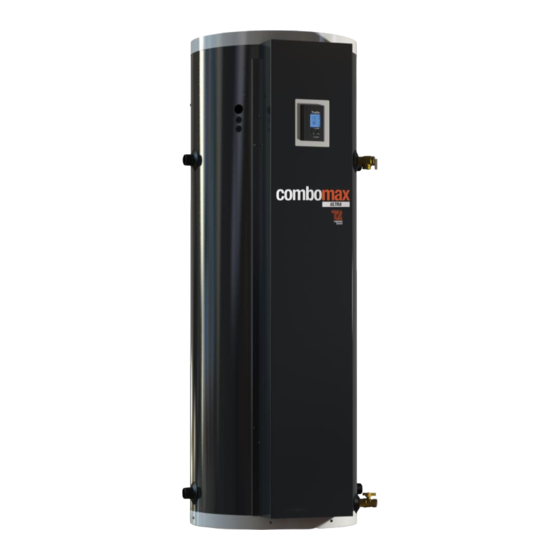
COMBOMAX ULTRA
Electric boiler with integrated instantaneous water heater
Power capacity : 4.5 kW to 29 kW :
120V- 208/240V (single phase)
INSTALLATION, USE AND CARE MANUAL
Your COMBOMAX ULTRA electric boiler has been carefully assembled and factory tested
to provide years of trouble-free service. This manual contains instructions for the safe and
proper installation, operation and maintenance of the boiler, in order to ensure your full
satisfaction.
It is imperative that all persons who are expected to install, operate or adjust this boiler read
the instructions carefully.
Any questions regarding the operation, maintenance, service or warranty of this water
heater should be directed to the dealer or distributor you purchased it from. When all
installation steps have been completed, replace this installation manual in its original
envelope, and keep in a safe place near the heater for future reference.
THERMO 2000 INC.
Printed in Canada
Revision : June 2016
Advertisement
Table of Contents

Related Manuals for COMBOMAX ULTRA

Summary of Contents for COMBOMAX ULTRA
- Page 1 120V- 208/240V (single phase) INSTALLATION, USE AND CARE MANUAL Your COMBOMAX ULTRA electric boiler has been carefully assembled and factory tested to provide years of trouble-free service. This manual contains instructions for the safe and proper installation, operation and maintenance of the boiler, in order to ensure your full satisfaction.
-
Page 2: Table Of Contents
6.1 AT ALL TIMES ..............................23 6.2 EVERY 6 MONTHS ............................23 6.3 YEARLY INSPECTION ............................. 23 6.5 SPARE PARTS ..............................24 COMBOMAX ULTRA LIMITED WARRANTY....................... 27 COMBOMAX ULTRA Electric Boiler Installation, Use and Care Manual , Page (Revision june 2016) -
Page 3: Section 1 : Technical Specifications
A higher cable size could be required. In all cases the local electrical code has priority. The electrician has the responsibility to select the appropriate size. These models are only available on the Combomax Ultra 70. Maximum operating pressure on the tank: 207 kPa / 30 psi Tank temperature range : 10°C to 88°C (50°F to 190°F) -
Page 4: Section 2 : Introduction
2.4 TO VERIFY Please check the boiler identification plate to ensure you have the right model. COMBOMAX ULTRA Electric Boiler Installation, Use and Care Manual , Page (Revision june 2016) -
Page 5: Section 3 : Installation
150 mm (6”) clearance from the floor as per NSF International recommendations. COMBOMAX ULTRA Electric Boiler Installation, Use and Care Manual , Page (Revision june 2016) -
Page 6: Piping Installation
(1/2’’ NPTM) Temperature and pressure Cold water supply indicator (3/4’’ NPTF) Thermostatic mixing valve (domestic water side) Figure 2: Components identification and location (Upper Compartment) COMBOMAX ULTRA Electric Boiler Installation, Use and Care Manual , Page (Revision june 2016) - Page 7 Model 70: 1 ¼’’ NPTM Modèle 50:1’’ NPTM Modèle 70: 1 ¼’’ NPTM Drain valve (Boiler water side) Figure 3: Components identification and location (Front Compartment) COMBOMAX ULTRA Electric Boiler Installation, Use and Care Manual , Page (Revision june 2016)
- Page 8 Figure 4: Installation drawing for radiant floor. Figure 5: Installation drawing for radiators. COMBOMAX ULTRA Electric Boiler Installation, Use and Care Manual , Page (Revision june 2016)
-
Page 9: System Setup
Connect the outlet of the relief valve downward Dielectric (insulating) unions should be used if toward a safe location. copper-steel connections are made. COMBOMAX ULTRA Electric Boiler Installation, Use and Care Manual , Page (Revision june 2016) -
Page 10: Operating Pressure Control & Expansion Tank
½ domestic hot water supply of the COMBOMAX NPTM nipple provided on the boiler. It also has ULTRA. to be well supported. COMBOMAX ULTRA Electric Boiler Installation, Use and Care Manual , Page (Revision june 2016) -
Page 11: Expansion Tank On The Cold Water Supply Line
In order to adjust the mixing valve, hot water must be consumed. (See section 5.6) COMBOMAX ULTRA Electric Boiler Installation, Use and Care Manual , Page (Revision june 2016) -
Page 12: Boiler Wiring
If the building heating system is made of multiple circulating pump and if the domestic hot water COMBOMAX ULTRA Electric Boiler Installation, Use and Care Manual , Page (Revision june 2016) -
Page 13: Dual-Energy Wiring With An Auxiliary Boiler
E (For Quebec: Red R wire and green V wire of Hydro-Quebec) Figure 7: Back of the Controller Figure 8: Wiring diagram in Dual-Energy COMBOMAX ULTRA Electric Boiler Installation, Use and Care Manual , Page (Revision june 2016) -
Page 14: Wiring Diagrams
3.10 WIRING DIAGRAMS COMBOMAX ULTRA Electric Boiler Installation, Use and Care Manual , Page (Revision june 2016) - Page 15 COMBOMAX ULTRA Electric Boiler Installation, Use and Care Manual , Page (Revision june 2016)
-
Page 16: Section 4 : Control Set Up
Actual Boiler Temperature The auxiliary boiler mode is selected Number of stages in operation Abnormal operation “COMBOMAX” program symbol Figure 9: UltraSmart Controller Display COMBOMAX ULTRA Electric Boiler Installation, Use and Care Manual , Page (Revision june 2016) -
Page 17: Interface Operation
4.3 INTERFACE OPERATION The Ultra Smart™ control access is through four (4) keys. provides access to the configuration menu and is also used as an « ENTER key » to confirm the selection. The two (2) rocking keys allow items selection or value change. -
Page 18: Operation In Dual-Energy
The water flow will then circulate only in the auxiliary boiler. COMBOMAX ULTRA Electric Boiler Installation, Use and Care Manual , Page (Revision june 2016) -
Page 19: User Adjusted Tank Temperature Set Point
“0” to be displayed. This zero indicates that the rocking keys are pressed. “user” differential value is zero. By using the keys, user input COMBOMAX ULTRA Electric Boiler Installation, Use and Care Manual , Page (Revision june 2016) -
Page 20: Section 5 : Operation
Section 5 : OPERATION SAFETY PRECAUTIONS Before operating the COMBOMAX ULTRA boiler, be sure to read and follow these instructions, as well as the warnings printed in this manual. Failure to do so can result in unsafe operation of the water heater resulting in property damage, bodily injury, or death. -
Page 21: Filling The Water Heater Tank
The most energy efficient elements will turned operation will result when the temperature succession. COMBOMAX ULTRA Electric Boiler Installation, Use and Care Manual , Page (Revision june 2016) -
Page 22: Thermostatically Controlled Mixing Valve Setting
In order to provide more domestic hot water, the amount of energy in the water heater tank need to be increase, this is achieved by increasing water tank temperature (maximum 88°C /190°F). COMBOMAX ULTRA Electric Boiler Installation, Use and Care Manual , Page (Revision june 2016) -
Page 23: Section 6 : Maintenance
Check for leaks at the heating elements, sign of overheating of electrical components and wiring. At the beginning of the heating season, check proper operation boiler controller, circulating pump(s), mixing COMBOMAX ULTRA Electric Boiler Installation, Use and Care Manual , Page (Revision june 2016) -
Page 24: Spare Parts
2 poles contactor ZEL100-24ACNO30 24Vac ZEL100-2PC5024 Transformer 208/240V x 24Vac Fuse ZEL400- 20842440 (40VA) ZEL250-TDMIDJ5 Figure 12: Electrical panel - Combomax Ultra 7,5 & 9 kW COMBOMAX ULTRA Electric Boiler Installation, Use and Care Manual , Page (Revision june 2016) - Page 25 24Vac ZEL100-4P50A24 Power Relay 24Vac ZEL100-24ACNO30 Transformer 208/240V x Fuse 24Vac ZEL250-TDMIDJ5 ZEL400- 20842440 (40VA) Figure 14: Electrical panel - Combomax Ultra 15 to 24 kW COMBOMAX ULTRA Electric Boiler Installation, Use and Care Manual , Page (Revision june 2016)
- Page 26 24Vac ZEL100-3P50A24 Power Relay 24Vac ZEL100-24ACNO30 Transformer 208/240V x 24Vac Fuse ZEL400- 20842440 (40VA) ZEL250-TDMIDJ5 Figure 15: Electrical panel - Combomax Ultra 27 & 29 kW COMBOMAX ULTRA Electric Boiler Installation, Use and Care Manual , Page (Revision june 2016)
-
Page 27: Combomax Ultra Limited Warranty
(1) leaking; or COMBOMAX ULTRA tank and exchanger is to be use in only one (1) A polybutylene pipe or radiant panel installation without an dwelling. In the event that a leak should develop and occur within this oxygen absorption barrier is used;...
Need help?
Do you have a question about the ULTRA and is the answer not in the manual?
Questions and answers