Table of Contents
Advertisement
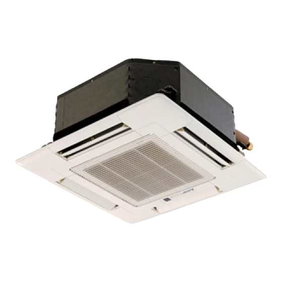
SPLIT-TYPE, HEAT PUMP AIR CONDITIONERS
TECHNICAL & SERVICE MANUAL
Indoor unit
[Model names]
SLZ-KA25VA
SLZ-KA35VA
SLZ-KA50VA
SLZ-KA25VAL
SLZ-KA35VAL
SLZ-KA50VAL
INDOOR UNIT
Model name
indication
ON/OFF
TOO
TOO
WARM
COOL
FAN
SELECT
AUTO COOL
VANE
TIME
HEAT
DRY
MODE
RESET
SLZ-KA25,35,50VAL.TH
REMOTE CONTROLLER
[Service Ref.]
SLZ-KA25VA.TH
SLZ-KA35VA.TH
SLZ-KA50VA.TH
SLZ-KA25VAL.TH
SLZ-KA35VAL.TH
SLZ-KA50VAL.TH
TEMP.
ON/OFF
SLZ-KA25,35,50VA.TH
Note :
•This manual does not cover
outdoor units. When servicing
outdoor units, please refer
to the service manual
No.OC322 together with this
manual.
CONTENTS
1. PART NAMES AND FUNCTIONS ········2
2. SPECIFICATIONS ·································5
3. OUTLINES AND DIMENSIONS ············7
4. WIRING DIAGRAM ·····························10
5. REFRIGERANT SYSTEM DIAGRAM ·······11
6. TROUBLESHOOTING ························12
7. 4-WAY AIR FLOW SYSTEM ···············19
8. DISASSEMBLY PROCEDURE ···········21
9. PARTS LIST ········································24
No. OC320
Advertisement
Table of Contents

Subscribe to Our Youtube Channel
Related Manuals for Mitsubishi SLZ-KA25VA


Summary of Contents for Mitsubishi SLZ-KA25VA
-
Page 1: Table Of Contents
No. OC320 TECHNICAL & SERVICE MANUAL Indoor unit Note : [Model names] [Service Ref.] •This manual does not cover outdoor units. When servicing SLZ-KA25VA.TH SLZ-KA25VA outdoor units, please refer to the service manual SLZ-KA35VA.TH No.OC322 together with this SLZ-KA35VA manual. -
Page 2: Part Names And Functions
PART NAMES AND FUNCTIONS Indoor Unit SLZ-KA25VAL.TH SLZ-KA25VA.TH SLZ-KA35VAL.TH SLZ-KA35VA.TH SLZ-KA50VAL.TH SLZ-KA50VA.TH Filter Remove dust and pollutants from inhaled air Horizontal Air Outlet Sets airflow horizontal automatically during cooling or dehumidifying. Grille Auto Air Swing Vane Disperses airflow up and down and adjusts the angle of airflow direction. - Page 3 Wired remote controller Once the controls are set, the same operation mode can be repeated by simply pressing the ON/OFF button. SLZ-KA25VA.TH SLZ-KA35VA.TH SLZ-KA50VA.TH Operation buttons [ PAR-21MAA ] Start/Stop button Set Temperature buttons Down Fan Speed button Timer Menu button...
- Page 4 Display “Sensor” indication Displayed when the remote controller sensor is used. Day-of-Week For purposes of this explanation, Shows the current day of the week. all parts of the display are shown as lit. During actual operation, only Time/Timer Display the relevant items will be lit. “Locked”...
-
Page 5: Specifications
SPECIFICATIONS SLZ-KA35VAL.TH SLZ-KA25VAL.TH SLZ-KA50VAL.TH Indoor model SLZ-KA35VA.TH SLZ-KA50VA.TH SLZ-KA25VA.TH Function Cooling Cooling Heating Cooling Heating Heating Single phase Single phase Single phase Power supply 230V, 50Hz 230V, 50Hz 230V, 50Hz Capacity Air flow (High/Medium/Low) K /h 600/540/480 660/540/480 660/540/480 Power outlet Running current 0.35... - Page 6 NOISE CRITERION CURVES <50Hz> <50Hz> SLZ-KA35VAL.TH SLZ-KA25VAL.TH NOTCH SPL(dB) LINE NOTCH SPL(dB) LINE SLZ-KA35VA.TH High SLZ-KA25VA.TH High Medium Medium NC-70 NC-70 NC-60 NC-60 NC-50 NC-50 NC-40 NC-40 NC-30 NC-30 APPROXIMATE APPROXIMATE TERESHOLD OF TERESHOLD OF HEARING FOR HEARING FOR NC-20...
-
Page 7: Outlines And Dimensions
OUTLINES AND DIMENSIONS SLZ-KA25VAL.TH Unit : mm SLZ-KA35VAL.TH SLZ-KA50VAL.TH SLZ-KA25VA.TH SLZ-KA35VA.TH SLZ-KA50VA.TH... - Page 8 Unit : mm WIRELESS REMOTE CONTROLLER 17.5 ON/OFF WARM COOL SELECT AUTO COOL VANE TIME HEAT MODE RESET Installation area • Area in which the remote controller is not exposed direct sunshine. • Area in which there is no nearby heating source. •...
- Page 9 Unit : mm WIRED REMOTE CONTROLLER...
-
Page 10: Wiring Diagram
WIRING DIAGRAM SLZ-KA25VAL.TH SLZ-KA25VA.TH SLZ-KA35VAL.TH SLZ-KA35VA.TH SLZ-KA50VAL.TH SLZ-KA50VA.TH GRILLE TO OUTDOOR UNIT AC220-240V CNSK(RED) TRANS (D·HEATER) (D·U·M) (POWER (FAN) (POWER) BOARD) CNDK (CONTROL) FUSE CN3C DC13.1V CN2S(WHT) PINK LED2 SKY BLU X5 X4 LED1 (POWER BOARD) CN2D LED3 <fig:w1> LED1... -
Page 11: Refrigerant System Diagram
REFRIGERANT SYSTEM DIAGRAM SLZ-KA25VAL.TH SLZ-KA25VA.TH SLZ-KA35VAL.TH SLZ-KA35VA.TH SLZ-KA50VAL.TH SLZ-KA50VA.TH Strainer Heat exchanger Refrigerant GAS pipe connection (Flare) Condenser/evaporator temperature thermistor (TH5) Refrigerant flow in cooling Refrigerant flow in heating Refrigerant LIQUID pipe connection (Flare) Pipe temperature thermistor/liquid Room temperature (TH2) -
Page 12: Troubleshooting
TROUBLESHOOTING 6-1. Cautions on troubleshooting (1) Before troubleshooting, check the followings: 1Check the power supply voltage. 2Check the indoor/outdoor connecting wire for mis-wiring. (2) Take care the followings during servicing. 1 Before servicing the air conditioner, be sure to first turn off the remote controller to stop the main unit, and then turn off the breaker. - Page 13 • Refer to the following tables for details on the check codes. [Output pattern A] Beeper sounds Beep Beep Beep Beep Beep Beep Beep OPERATION · · · Repeated INDICATOR lamp flash pattern Approx. 2.5 sec. 0.5 sec. 0.5 sec. 0.5 sec.
- Page 14 • On wireless remote controller 2The continuous buzzer sounds from receiving section of indoor unit. 3Blink of operation lamp • On wired remote controller 1Check code displayed in the LCD. • If the unit cannot be operated properly after the above test run has been performed, refer to the following table to remove the cause. Symptom Cause Wired remote controller...
- Page 15 6-3. Test point diagram 6-3-1. Indoor power board SLZ-KA25VAL.TH SLZ-KA25VA.TH SLZ-KA35VAL.TH SLZ-KA35VA.TH SLZ-KA50VAL.TH SLZ-KA50VA.TH CN2S Connect to the indoor controller board (CN2D) Between 1 1 to 3 3 12.6-13.7V DC (Pin1 1 (+)) CNSK Connect to the indoor controller board...
- Page 16 6-3-2. Indoor controller board SLZ-KA25VAL.TH SLZ-KA25VA.TH SLZ-KA35VAL.TH SLZ-KA35VA.TH SLZ-KA50VAL.TH SLZ-KA50VA.TH CN2D LED1 Connector to the indoor LED2 LED3 Power supply power board (CN2S) Power supply Transmission (I.B) (12.5~13.7V DC) (R.B) (Indoor/outdoor) CN3C – Transmission (Indoor/outdoor) CN22 (0~24V DC) Remote controller...
- Page 17 6-4. Trouble criterion of main parts SLZ-KA25VAL.TH SLZ-KA25VA.TH SLZ-KA35VAL.TH SLZ-KA35VA.TH SLZ-KA50VAL.TH SLZ-KA50VA.TH Part name Check method and criterion Room temperature Measure the resistance with a tester. thermistor (Part temperature 10°C ~ 30°C) (TH1) Normal Abnormal Pipe temperature 4.3kΩ~9.6k" Opened or short-circuited...
- Page 18 <Thermistor Characteristic graph> •Room temperature thermistor (TH1) < Thermistor for lower temperature > Thermistor for •Pipe temperature thermistor/liquid (TH2) lower temperature •Condenser/evaporator temperature thermistor (TH5) Thermistor R =15k' ± 3% Fixed number of B=3480 ± 2% Rt=15exp { 3480( 273+t 15k' 9.6k' 6.3k'...
-
Page 19: Way Air Flow System
Ceiling surface Drain pipe Electrical Box Refrigerant pipe 7-2. Fresh air intake amount & static pressure characteristics SLZ-KA25VAL.TH SLZ-KA25VA.TH SLZ-KA35VAL.TH SLZ-KA35VA.TH SLZ-KA50VAL.TH SLZ-KA50VA.TH Taking air into the unit How to read curves Q … Planned amount of fresh air intake... - Page 20 7-4. Fixing of horizontal vane Horizontal vane of each air outlet can be fixed according to the environment, which is installed. Setting procedure 1) Turn off a main power supply (Turn off a breaker). 2) Disconnect the vane motor connector of the direction of the arrow with pressing the unlocking button as shown in figure below.
-
Page 21: Disassembly Procedure
DISASSEMBLY PROCEDURE SLZ-KA25VAL.TH SLZ-KA35VAL.TH SLZ-KA50VAL.TH Be careful on removing heavy parts. OPERATING PROCEDURE PHOTOS&ILLUSTRATIONS 1. Removing the air intake grille Figure 1 (1) Slide the knob of air intake grille to the direction of the arrow 1 to open the air intake grille. Air intake grille (2) Remove the hook for secure belt on air inlet grille from the panel. - Page 22 OPERATING PROCEDURE PHOTOS&ILLUSTRATIONS 5. Remove the room temperature thermistor (TH1) Photo 4 (1) Remove the panel. (Refer to 3) Connectors (2) Pull out the room temperature thermistor from the drain pan. Drain plug Control box (3) Remove the 2 screws fixed to the control box cover, and remove the control box cover.
- Page 23 OPERATING PROCEDURE PHOTOS&ILLUSTRATIONS 9. Removing the drain pump (DP) and drain sensor (DS) Photo 7 Cover Screw (1) Remove the panel. (Refer to 3 ) (2) Remove the drain pan. (Refer to 6) (3) Remove the 2 screws fixed to the control box cover, and Control remove the control box cover.
-
Page 24: Parts List
PARTS LIST PANEL PARTS SLP-2AL SLP-2AA Price Q'ty/set Wiring Recom- Remarks Parts No. Parts name Specification Diagram mended (Drawing No.) Unit Amount SLP-2AL SLP-2AA Symbol Q'ty E07 103 003 AIR OUTLET GRILLE E07 158 003 AIR OUTLET GRILLE E07 103 317 WIRELSS REMOTE CONTROL BOARD E07 103 037 AUTO VANE... - Page 25 ELECTRICAL PARTS SLZ-KA25VAL.TH SLZ-KA25VA.TH SLZ-KA35VAL.TH SLZ-KA35VA.TH SLZ-KA50VAL.TH SLZ-KA50VA.TH Q'ty/set Wiring Recom- Price Remarks SLZ-KA Parts No. Specification Parts name Diagram mended (Drawing No.) Symbol Q'ty Unit Amount VAL.TH VA.TH E07 006 382 FUSE 250V 6.3A FUSE E02 661 385 VARISTOR...
- Page 26 FUNCTIONAL PARTS SLZ-KA25VAL.TH SLZ-KA35VAL.TH SLZ-KA50VAL.TH SLZ-KA25VA.TH SLZ-KA35VA.TH SLZ-KA50VA.TH ON/OFF WARM COOL SELECT AUTO COOL VANE TIME HEAT MODE RESET TEMP. ON/OFF...
- Page 27 Q'ty/set Price Wiring Recom- SLZ- Remarks Parts No. Parts name Specification Diagram mended (Drawing No.) Unit Amount Symbol Q'ty VAL.TH VA.TH E07 104 290 BASE E07 104 124 DRUM-1 E07 104 808 LEG-1 DRUM-2 E07 105 124 E07 140 620 INDOOR HEAT EXCHANGER E07 141 620 INDOOR HEAT EXCHANGER...
- Page 28 HEAD OFFICE : MITSUBISHI DENKI BLDG., 2-2-3, MARUNOUCHI, CHIYODA-KU, TOKYO 100-8310, JAPAN CCopyright 2005 MITSUBISHI ELECTRIC ENGINEERING CO., LTD. New publication, effective Feb. 2005. Distributed in Feb. 2005 No.OC320 PDF 8 Specifications subject to change without notice. Made in Japan.
Need help?
Do you have a question about the SLZ-KA25VA and is the answer not in the manual?
Questions and answers