Table of Contents

Related Manuals for Abus TVIP41560


Summary of Contents for Abus TVIP41560
-
Page 1: User Manual
TVIP41560 / TVIP61560 User manual You can find important information and FAQs about this and other products online at: www.abus.com Version 1.0 English translation of the original German user manual. Retain for future reference. - Page 2 ABUS Security-Center GmbH is not liable or responsible for direct or indirect damage resulting from the equipment, performance and use of this product. No guarantee is made for the contents of this...
-
Page 3: Intended Use
English Explanation of symbols The triangular high voltage symbol is used to warn of the risk of injury or health hazards (e.g. caused by electric shock). The triangular warning symbol indicates important notes in this user manual which must be observed. This symbol indicates special tips and notes on the operation of the device. - Page 4 English Power supply • Only operate this device through a power source which supplies the mains power specified on the type plate. If you are unsure which power supply is available, contact your utility company. • Disconnect the device from the power supply before carrying out maintenance or installation work. •...
- Page 5 English Installation location/operating environment Operating temperature and operating humidity: -20°C to 50°C, maximum 95% relative humidity. Ensure that: • no direct sources of heat (e.g. radiators) can affect the device • the image sensor is not exposed to direct sunlight or strong artificial light •...
- Page 6 English Start-up • Observe all safety and operating instructions before operating the device for the first time. Warning When installing the device in an existing video surveillance system, ensure that all devices have been disconnected from the mains power circuit and low-voltage circuit. Warning Improper or unprofessional work on the power supply system or domestic installations puts both you and others at risk.
-
Page 7: Table Of Contents
English Contents 1. Scope of delivery ..........................79 1.1. TVIP41560 ..........................79 1.2. TVIP61560 ..........................79 2. Camera description ........................... 80 2.1. TVIP41560 ..........................80 2.2. TVIP61560 ..........................81 3. Description of the connections ......................81 4. Mounting/installation .......................... 82 4.1. - Page 8 English 10.3.3.1. Video .......................... 113 10.3.4. Image ........................... 115 10.3.4.1. Display Settings ......................116 10.3.4.2. OSD Settings ......................119 10.3.4.3. Text Overlay ......................120 10.3.4.4. Privacy Mask ......................121 10.3.5. Security ........................122 10.3.5.1. User ........................... 123 10.3.5.2. IP Address Filter ......................124 10.3.6.
-
Page 9: Scope Of Delivery
English 1. Scope of delivery 1.1. TVIP41560 WLAN HD 720p Outdoor Dome 1 m network cable Camera Installation material Quickstart guide 1.2. TVIP61560 WLAN HD 720p Outdoor Camera 1 m network cable Installation material Quickstart guide... -
Page 10: Camera Description
WPS/reset button & microSD card slot inside Reset: (applies to TVIP41560 and TVIP61560) To reset the camera to its factory settings, first disconnect the power supply. Keep the WPS/reset button pressed and reconnect the power supply to the camera. Continue pressing... -
Page 11: Tvip61560
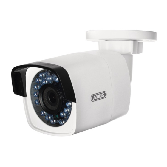
English 2.2. TVIP61560 Description Base plate WPS/reset button & microSD card slot inside Lens Photo sensor for day/night switching IR LEDs Sun shield 3. Description of the connections Description 12 V DC power supply connection (round plug 5.5x2.1 mm) Network access (RJ45, PoE-compatible) The network access includes a cover, which can be used if necessary. -
Page 12: Mounting/Installation
English 4. Mounting/installation 4.1. TVIP41560 4.1.1. Mounting the camera IMPORTANT! The camera must be disconnected from the power supply during installation. Loosen the fixing screws for the camera dome and remove them. Use the accompanying drilling template for drilling the mounting holes. -
Page 13: Orientation Of The Camera
English 4.1.2. Orientation of the camera First, undo the black dome cover. Loosen the screws at the side of the bracket to align the lens. The camera can be aligned in three axes. Setting the panning angle. Panning: 0°–355° Setting the angle of inclination. Inclination: 0°–65°... -
Page 14: Orientation Of The Camera
English 4.2.2. Orientation of the camera The camera can be aligned in three axes. Panning: 0°–360° Loosen the rotary wheel (1) to adjust the alignment horizontally. Inclination: 0°–90° Loosen the screw (2) to adjust the alignment vertically. Rotation: 0°–360° Loosen the screw (3) to adjust the rotation of the camera image. Do not forget to tighten up the screws again! -
Page 15: Initial Start-Up
English 5. Initial start-up The network camera automatically detects whether a direct connection between the PC and camera should be established. A crossover network cable is not required for this. You can use the supplied patch cable for direct connection for initial start-up. Connecting the network camera directly to a PC/laptop 1. -
Page 16: Accessing The Network Camera For The First Time
6. Accessing the network camera for the first time The network camera is accessed for the first time using the ABUS IP Installer. After the installation wizard is started, it searches for all connected ABUS network cameras and video servers on your network. -
Page 17: Password Prompt
English 7. Password prompt An administrator password is defined for the network camera prior to delivery. For reasons of security, however, the administrator should select a new password immediately. After this administrator password has been saved, the network camera asks for the user name and password every time it is accessed. -
Page 18: User Functions
English 8. User functions Open the network camera home page. The interface is divided into the following main areas: Menu bar Live image display Video control 8.1. Menu bar Make a selection by clicking on the appropriate tab: "Live View", "Playback", "Configuration" or "Log". Button Description Display of the user logged on... -
Page 19: Live Image Display
English 8.2. Live image display You can access the full-screen view by double-clicking. Button Description Activate 4:3 view Activate 16:9 view Display original size Automatically adjust view to browser Selection of the streaming type for the live view 8.3. Video control Button Description Disable live view... -
Page 20: Playback
English 9. Playback In playback, you can play back data that is recorded on the microSD card or network drive. Select the desired day in the calendar and click on "Search". The recordings for the selected day are shown in the timeline. The coloured labelling indicate the nature of the event that triggered the recording. -
Page 21: Configuration
English 10. Configuration When making settings in the individual menu items, you must click "Save" first to adopt these settings. The "Save" button can usually be found at the bottom of the individual menu tabs on the right hand side. 10.1. - Page 22 English Rules Display of all event animations in the live image (e.g. frame for motion detection). These animations are also recorded to the recording device. Picture format Select the encoding format for saving single frames using the browser live interface. Record file settings Record file size Select the size of video sequences for saving videos using the browser live interface.
-
Page 23: Basic Configuration
English 10.2. Basic Configuration Under "Basic Configuration", you will find the relevant settings for network configuration, motion detection, saving to an SD card and sending emails. All settings located under "Basic Configuration" can also be found under the menu item "Advanced Configuration". -
Page 24: Advanced Configuration
English 10.3. Advanced configuration 10.3.1. System Menu item Description Available in mode Device Information Display of device information Basic Configuration, Advanced Configuration Time Settings Configuration of the time specification Advanced Configuration Maintenance Configuration of system maintenance settings Basic Configuration, Advanced Configuration Configuration of the automatic daylight saving Advanced Configuration time switch... -
Page 25: Device Information
English 10.3.1.1. Device Information Basic Information Device Name: You can specify a device name for the camera here. Click on "Save" to apply the change. Model: Model number display Serial No.: Serial No. display Firmware Version: Firmware version display Encoding Version: Encoding version display Number of Channels: Display of the number of channels... -
Page 26: Time Settings
English 10.3.1.2. Time Settings Time Zone Time zone selection (GMT). Time Sync. Using the Network Time Protocol (NTP), it is possible to synchronise the time of the camera with a time server. Enable NTP to use this function. Server Address IP server address of the NTP server. -
Page 27: Maintenance
English 10.3.1.3. Maintenance Reboot Click "Reboot" to reboot the device. Default Restore Click on "Restore" to reset all the parameters, except the IP parameters and user information, to the default settings. Default Select this item to restore all parameters to default settings. Import Config. -
Page 28: Dst
English 10.3.1.4. DST Enable DST Select "Enable DST" to adjust the system time automatically to daylight saving time. Start time Specify the time for switching to daylight saving time. End Time Specify the time for switching to standard time. DST Bias Set the time difference in minutes here. -
Page 29: Network
English 10.3.2. Network Menu item Description Available in mode TCP/IP Settings for the TCP/IP data Basic Configuration, Advanced Configuration Port Settings for the used ports Advanced Configuration DDNS Settings for the DDNS data Advanced Configuration FTP server settings Advanced Configuration Wi-Fi Settings for the W-LAN access data Basic Configuration,... -
Page 30: Tcp/Ip
English 10.3.2.1. TCP/IP NIC settings To be able to operate the camera via a network, the TCP/IP settings must be configured correctly. DHCP If a DHCP server is available, click on "DHCP" to apply an IP address and other network settings automatically. - Page 31 English IPv6 Mode Manual: Manual configuration of IPv6 data. DHCP: The IPv6 connection data is provided by the DHCP server. Route Advertisement: The IPv6 connection data is provided by the DHCP server (router) in connection with the ISP (Internet Service Provider). IPv6 Address Display of the IPv6 address.
-
Page 32: Port
English 10.3.2.2. Port If you wish to enable external access to the camera, the following ports must be configured. HTTP Port The default port for HTTP transmission is 80. This port can alternatively be assigned a value in the range of 1024~65535. If several cameras are located on the same subnetwork, each camera should have its own unique HTTP port. -
Page 33: Ddns
Select a DDNS service provider. You must have registered access to this DDNS service provider (e.g. www.dyndns.org). If you select "ABUS DDNS" as the DDNS type, the server address is stored automatically. Domain Enter the registered domain name (host service) here (e.g. myIPcamera.dyndns.org). - Page 34 English ABUS DDNS To be able to use the ABUS DDNS function, you first need to set up an account at www.abus- server.com. Please read the FAQs on this topic on the website. Select the "Enable DDNS" checkbox and select "ABUS DDNS" as the DDNS type.
-
Page 35: Ftp
English 10.3.2.4. FTP Server Address Enter the IP address or host name of the FTP server to which images are to be uploaded here. Port Enter your FTP server's port here. Ports 21 or 20 are used as standard. User name Enter the user name here. -
Page 36: Wi-Fi
English 10.3.2.5. Wi-Fi The following settings must be made to create a Wi-Fi connection between the camera and the router. Wi-Fi list Click "Search" to display available networks in the immediate vicinity. Please note that hidden networks are not shown in the list! Wi-Fi SSID Enter the name of the network here. - Page 37 English Security Mode Here you can select the encryption type for your network. Encryption Type: Here you can select the encryption type for the network. Key 1 Enter the network key (password) for access to the network here. NIC settings To be able to operate the camera via a network, the TCP/IP settings must be configured correctly.
-
Page 38: Upnp
English 10.3.2.6. UPnP™ The UPnP (Universal Plug and Play) function makes it easy to control network devices in an IP network. This allows the network camera to be seen in the Windows network environment (e.g. as a network device). Enable UPnP™ For enabling or disabling the UPnP function. -
Page 39: Email
English 10.3.2.7. Email You can apply the settings for sending emails here. Sender Sender Enter a name here to be displayed as the sender. Sender's Address Enter the email address of the sender here. SMTP server Enter the IP address or host name of the SMTP server here. (For example: smtp.gmail.com) SMTP port Enter the SMTP port here. - Page 40 English Authentication If the email server in use requires authentication, enable this function to be able to log onto the server with authentication. User names and passwords can only be entered once this function has been enabled. User name Enter the user name of the email account here. Password Enter the password of the email account here.
-
Page 41: Nat
English 10.3.2.8. NAT Enable Port Mapping This enables Universal Plug and Play port forwarding for network services. If your router supports UPnP, using this option means that port forwarding is enabled automatically. Port Mapping Mode Select here whether you wish to conduct port mapping automatically or manually. Protocol Name: HTTP The default port for HTTP transmission is 80. -
Page 42: Video/Audio
English 10.3.3. Video/Audio Menu item Description Available in mode Video Settings for video output Advanced Configuration... -
Page 43: Video
English 10.3.3.1. Video Stream Type Select the stream type that you wish to set for the camera. Select "Main Stream (Normal)" for recording and live view with good bandwidth. Select "Sub Stream" for live view with restricted bandwidth. Video Type Set the video type for the selected stream here. - Page 44 English Profile here you can select the profile type for the video codec. A profile is standardised and determines the parameters that should be used for encoding. I frame interval select how often an I frame should be sent (H.264 only). The more often an I frame (full image) is sent, the better the video quality is, but the more bandwidth is required.
-
Page 45: Image
English 10.3.4. Image Menu item Description Available in mode Display Settings Displaying parameter settings Advanced Configuration OSD Settings Setting the date and time format Advanced Configuration Text Overlay Adding text fields Advanced Configuration Privacy masking Adding privacy masking Advanced Configuration... -
Page 46: Display Settings
English 10.3.4.1. Display Settings You can use this menu item to set the picture quality of the camera, including brightness, sharpness, contrast, etc. Please note: The display setting parameters can vary depending on the model. Day and night switching Here, you have the option between automatic day & night switch and the scheduled switch. A start and end time must be saved for the day mode here. - Page 47 English Sharpness Image sharpness settings. A higher sharpness value can increase image noise. A value between 0 and 100 can be set. Exposure Time Setting the maximum exposure time. This setting is dependent on iris mode. Day/Night Switch Day/Night Switch Provides options for Auto, Day and Night time schedule and triggered by alarm input.
- Page 48 English BLC Area (Backlight Compensation) Objects in front of a bright background can be shown more clearly with the aid of the backlight compensation. The exposure of the objects is corrected, however the background is not shown in focus. With the aid of the WDR function, the camera can return clear pictures even in disadvantageous backlight conditions.
-
Page 49: Osd Settings
English 10.3.4.2. OSD Settings You can use this menu item to select the format of the date and time displayed in the live picture. Display Name Activate this checkbox if you wish to display the camera name. Display Date Activate this checkbox if you wish to display the date in the camera image. Display Week Activate this checkbox if you wish to display the day of the week. -
Page 50: Text Overlay
English 10.3.4.3. Text Overlay You have the option to display up to four texts in the camera image. The maximum length is 45 characters. To display the text, please activate the checkbox. You can move the text window with the mouse button. -
Page 51: Privacy Mask
English 10.3.4.4. Privacy Mask You can use privacy masks to hide certain areas in the live view to prevent these areas from being recorded and viewed in the live view. A maximum of four rectangular privacy masks can be set up in the video image. -
Page 52: Security
English 10.3.5. Security Menu item Description Available in mode User User administration Basic Configuration, Advanced Configuration IP Address Filter Filtering IP addresses to gain access for controlling the Advanced Configuration camera... -
Page 53: User
English 10.3.5.1. User With this menu item, you can add, edit or delete users. To add or modify a user, click "Add" or "Modify". A new window with the data and authorisations appears. User name Here you assign the user name that needs to be entered for access to the camera. Level Select an individual user type for the user ID. -
Page 54: Ip Address Filter
English 10.3.5.2. IP Address Filter Enable IP Address Filter Ticking the selection box enables the filter function. IP Address Filter Type Allowed: The IP addresses detailed further below can be used to access the camera. Forbidden: The IP addresses detailed further below are blocked. An IP is entered in the format xxx.xxx.xxx.xxx. -
Page 55: Basic Event
English 10.3.6. Basic event Menu item Description Available in mode Motion detection Settings for motion detection Basic Configuration Advanced Configuration Snapshot Setting the event-triggered snapshot Advanced Configuration... -
Page 56: Motion Detection
English 10.3.6.1. Motion detection Enable motion detection Check this box to enable motion detection. Enable dynamic analysis for motion Check this box to highlight with a green frame when motion is detected. The rules must also be enabled in the Local Settings here. - Page 57 English Configuration Select either "Normal" or "Expert" mode. Normal Area Settings To select an area, click on the "Draw Area" button. The entire area is selected by default. To discard this selection, click on "Clear All". Drag the mouse pointer over the desired area. To apply the setting for the area, click on "Stop Drawing".
- Page 58 English Arming Schedule To save a schedule for motion-controlled recording, click on "Edit". A new window appears. Specify here on which days of the week and at which times motion-controlled recording should take place. Now select a day of the week for motion-controlled recording. To store particular time periods, enter a start and end time.
-
Page 59: Event-Triggered Snapshot
English 10.3.6.2. Event-triggered snapshot Event-Triggered Enable Event-Triggered Snapshot Enable this function to save event-triggered pictures. Format The format for the pictures is preconfigured as JPEG. Resolution Set the resolution of the picture here. Quality Select the quality for the saved pictures here. Interval Set the interval to occur between the saving of two pictures here. -
Page 60: Storage
English 10.3.7. Storage Menu item Description Available in mode Record Schedule Set up a scheduled recording Basic Configuration, Advanced Configuration Storage Management Management of the SD card, network drives Advanced Configuration Network drive settings Advanced Configuration Snapshot Settings for the event-triggered snapshot Advanced Configuration... -
Page 61: Recording Plan
English 10.3.7.1. Recording plan Here, you can configure time and event-triggered recordings in order to be able to save them to an SD card or a network drive. Pre-record Set the duration for recording of the image data before a basic event here. Post-record Set the duration for recording of the image data after a basic event here. - Page 62 English Enable Record Schedule Enable the schedule to store the desired schedule. To store the schedule, click "Edit". A new window opens. Now select a day of the week for the recording to take place. To store particular time periods, enter a start and end time.
-
Page 63: Storage Management
English 10.3.7.2. Storage Management Here, you can format the inserted micro SD card or network drives and display their properties. Percentage of Picture Enter the percentage that should be taken up by snapshot images here. Percentage of Record Enter the percentage that should be taken up by recordings here. Please format the SD card or the network drive before using it for the first time! - Page 64 English 10.3.7.3. NAS You can configure storage of the recordings on up to eight NAS devices here. Click in a row to specify server address, file path, server type, user name and password. Server Address Enter the IP address or host name of your NAS or network drive here. File path Enter the file path in which the data will be saved.
-
Page 65: Time-Triggered Snapshot
English 10.3.7.4. Time-triggered snapshot Here, you can configure event-triggered snapshots in order to be able to save them to the microSD card or network drive. Timing Enable Timing Snapshot Enable this function to save pictures at certain intervals. Format The format for the pictures is preconfigured as JPEG. Resolution Set the resolution of the picture here. -
Page 66: Protocol
English 11. Protocol Camera parameters, such as alarm, exceptions, operation and information can be saved in the log files. The files can be exported if necessary. 1. Click on Log in the menu bar to call up the search dialogue. 2. -
Page 67: Technical Data
Day/night switching Electromechanically removable IR cut filter (ICR) Supported browsers Mozilla Firefox, Safari or Internet Explorer 6.x and higher Supported software ABUS VMS Express, IPCam App (iOS/Android) Encryption 64/128 bit WEP, WPA/WPA2, WPA-PSK/WPA2-PSK, WPS Video compression H.264, MJPEG White balance... -
Page 68: Disposal
14. GPL license information We wish to inform you that the TVIP41560 / TVIP61560 network surveillance cameras, amongst others, include open source software licensed exclusively under the GNU General Public Licence (GPL). To ensure that your use...
Need help?
Do you have a question about the TVIP41560 and is the answer not in the manual?
Questions and answers