Salus VS35W Installer's/User's Manual
Hide thumbs
Also See for VS35W:
- Installation manual (2 pages) ,
- User manual (32 pages) ,
- Full user manual (28 pages)

Related Manuals for Salus VS35W


Summary of Contents for Salus VS35W
- Page 1 VS35W - VS35B Installer - User Manual 006_Layout 1 10.10.2014 11:59 Digital Thermostat Models: VS35W and VS35B I N S TA L L E R / U S E R M A N U A L...
- Page 2 VS35W - VS35B Installer - User Manual 006_Layout 1 10.10.2014 11:59 Contents Contents Icons used in this manual: For latest PDF installation guide please go to Box Contents www.salus-controls.com Safety Introduction Product Compliance Installation Important info User Guide Parameter Settings...
- Page 3 VS35W - VS35B Installer - User Manual 006_Layout 1 10.10.2014 11:59 Product Compliance & Safety Information INTRODUCTION Safety Information Use in accordance with the regulations. Thank you for purchasing the room thermostat The VS35 is to be used for room VS35.
- Page 4 VS35W - VS35B Installer - User Manual 006_Layout 1 10.10.2014 11:59 Product Compliance & Safety Information Sources of danger Installer parameter settings The thermostat must be disconnected from mains The VS35 is equipped with installer parameter section. supply before removing the cover.
- Page 5 VS35W - VS35B Installer - User Manual 006_Layout 1 10.10.2014 12:00 Installation – Terminal Connections Understanding your terminal connections Power Terminals 230 Vac Used for supplying power to the Rear of VS35 unit and switched output. NSB (Night Set Back) Connection...
- Page 6 VS35W - VS35B Installer - User Manual 006_Layout 1 10.10.2014 12:00 Installation – Thermostat Mounting Gently remove front housing. Gently remove front housing. Wall Mounting For wall mounting, mark and mount the rear case to the wall. The VS35 is suitable for wall boxes...
- Page 7 VS35W - VS35B Installer - User Manual 006_Layout 1 10.10.2014 12:00 Installation – Thermostat Mounting Mounting position and installation To ensure trouble free operation and efficient control, the VS35 room thermostat is best positioned in a draft free area, and at 130cm from the floor. Do not position the thermostat near any heat source, behind curtains, direct sunlight or an area of high humidity.
- Page 8 VS35W - VS35B Installer - User Manual 006_Layout 1 10.10.2014 12:00 Installation – Terminal Connections Sensor Terminal (optional) Sensor Terminal (optional) Night set back input Optional SALUS Sensor Load (Thermal Actuators) NSB from other Live 230V AC 50Hz thermostats...
- Page 9 VS35W - VS35B Installer - User Manual 006_Layout 1 10.10.2014 12:00 Installation – Terminal Connections Check that the wiring is completed for: Power Terminals NSB (Night Set Back) Connection Sensor Terminals (if applicable) You are ready to secure the rear housing to the wall box...
- Page 10 VS35W - VS35B Installer - User Manual 006_Layout 1 10.10.2014 12:00 Installation – Thermostat Mounting Fit the front housing to the rear housing Ensure the pin connections are aligned Align the front housing Lightly press until you hear a positive click.
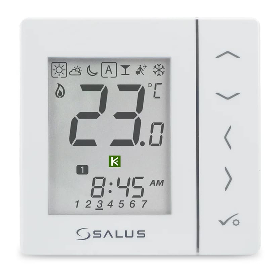
- Page 11 VS35W - VS35B Installer - User Manual 006_Layout 1 10.10.2014 12:00 Installation – LCD Graphics VS35W and VS35B Installer / User Manual...
- Page 12 VS35W - VS35B Installer - User Manual 006_Layout 1 10.10.2014 12:00 Installation – LCD Graphics ICON FUNCTION BOX means to select the mode e.g. means the current setpoint is Hi temp, means the Hi temp is not selected. Sunny: Hi comfortable temperature.
- Page 13 VS35W - VS35B Installer - User Manual 006_Layout 1 10.10.2014 12:00 Installation – LCD Graphics ICON FUNCTION Temperature indicator: Display the room temperature. Display the set-temp. Also used to show the other information. Temporary manual override indicator: If the set temperature is changed when in program mode, the hand will appear until the next program start time.
- Page 14 VS35W - VS35B Installer - User Manual 006_Layout 1 10.10.2014 12:00 Installation – User Interface FUNCTION 1. Increase or decrease setpoint temperature. 2. Increase or decrease Day, Clock, Timer, Party and Holiday. 3. Select installer parameter value. 1. Mode selection.
- Page 15 VS35W - VS35B Installer - User Manual 006_Layout 1 10.10.2014 12:00 Installation – First Power Up Software Version 2 Seconds 2 Seconds Version will change from unit to unit. VS35W and VS35B Installer / User Manual...
- Page 16 VS35W - VS35B Installer - User Manual 006_Layout 1 10.10.2014 12:00 Installation - Graphics Key Press once Press x amount of times Hold for five seconds Flashing Short press to save and Short press to back up long press to save and exit...
- Page 17 VS35W - VS35B Installer - User Manual 006_Layout 1 10.10.2014 12:00 User Guide – Understanding Temperature Levels - Heating Highest Temperature typically used for early morning and early evening. Typically 20 Deg C Mid Temperature typically used for times of day when you are active around the home.
- Page 18 VS35W - VS35B Installer - User Manual 006_Layout 1 10.10.2014 12:00 User Guide - Understanding Temperature Levels - Cooling Occupied Temperature. Typically 22ºC Unoccupied Temperature Typically 40ºC This avoids cooling being active when the property is unoccupied. Evening Temperature Typically 26ºC...
- Page 19 VS35W - VS35B Installer - User Manual 006_Layout 1 10.10.2014 12:00 User Guide - Permanent Override Setting permanent low temperature Move from Use the up or down arrow key to view your set temperature. To cancel permanent override select...
- Page 20 VS35W - VS35B Installer - User Manual 006_Layout 1 10.10.2014 12:00 User Guide - Frost Protection Use the right arrow to select the frost mode. Use the up arrow to select the frost protection temperature. Press tick to confirm...
- Page 21 VS35W - VS35B Installer - User Manual 006_Layout 1 10.10.2014 12:00 User Guide - Heat cool change over VS35W and VS35B Installer / User Manual...
- Page 22 VS35W - VS35B Installer - User Manual 006_Layout 1 10.10.2014 12:01 User Guide - Heat cool change over VS35W and VS35B Installer / User Manual...
- Page 23 VS35W - VS35B Installer - User Manual 006_Layout 1 10.10.2014 12:01 Installation - Entering Device Menu Press all three buttons If you need to simultaneously. change device parameters follow the steps below. Must only be entered by the installer.
- Page 24 VS35W - VS35B Installer - User Manual 006_Layout 1 10.10.2014 12:01 Installation - Device Parameters FUNCTION SYSTEM SETTING DEFINITION DEFAULT Heating Pulse Width Modulation Control On-Off 0.5 Deg C +/- 0.25 Deg C On-Off 1.0 Deg C +/- 0.5 Deg C Room -3.0 to 3.0...
- Page 25 VS35W - VS35B Installer - User Manual 006_Layout 1 10.10.2014 12:01 Installation - Device Parameters continued FUNCTION SYSTEM SETTING DEFINITION DEFAULT Frost Set point 5-17 Deg C Required Temperature for frost 5 Deg Temperature protection and holiday mode Hour Format...
- Page 26 VS35W - VS35B Installer - User Manual 006_Layout 1 10.10.2014 12:01 Installation - Device Parameters continued FUNCTION SYSTEM SETTING DEFINITION DEFAULT Preset program Select 1-5 of the default programs selection Heat/Cool mode 0: heating mode 0 or 1 selection...
- Page 27 VS35W - VS35B Installer - User Manual 006_Layout 1 10.10.2014 12:01 Installation - Technical Detail Model VS35W/B Type Digital room thermostat designed for 230V AC applications Modes Frost 230V Input Override Permanent Frost Protection 5ºC Adjustable Power Source 230V AC 50Hz...
- Page 28 VS35W - VS35B Installer - User Manual 006_Layout 1 10.10.2014 12:01 Installation - Notes VS35W and VS35B Installer / User Manual...
- Page 29 VS35W - VS35B Installer - User Manual 006_Layout 1 10.10.2014 12:01 Installation - Notes VS35W and VS35B Installer / User Manual...
- Page 30 SALUS Controls warrants that this product will be free from any defect in materials or workmanship, and shall perform in accordance with its specification, for a period of five years from the date of installation. SALUS Controls sole liability for breach of this warranty will be (at its option) to repair or replace the defective product.
- Page 31 VS35W - VS35B Installer - User Manual 006_Layout 1 10.10.2014 12:01 Digital Thermostat Models: VS35W and VS35B VS35W and VS35B Installer / User Manual...
- Page 32 SALUS Controls is a member of the Computime Group Maintaining a policy of continuous product development SALUS Controls plc reserve the right to change specification, design and materials of products listed in this brochure without prior notice. Issue Date: April 2014...
Need help?
Do you have a question about the VS35W and is the answer not in the manual?
Questions and answers
Are the pre-set heat settings set to times?