Salus VS35W Full User Manual
Hide thumbs
Also See for VS35W:
- Installer's/user's manual (33 pages) ,
- Installation manual (2 pages) ,
- User manual (32 pages)
Table of Contents
Advertisement
Quick Links
Advertisement
Table of Contents

Subscribe to Our Youtube Channel
Related Manuals for Salus VS35W


Summary of Contents for Salus VS35W
- Page 1 VS35W/VS35B THERMOSTAT - FULL USER MANUAL...
-
Page 3: Table Of Contents
TABLE OF CONTENTS 1. Introduction ................................4 1.1 Product Compliance ..................................4 1.2 Safety Informations ..................................4 1.3 Product Overview ..................................5 2. Montage ..................................6 2.1 Package content ....................................6 2.2 Proper thermostat location ................................6 2.3 Wall mounting ....................................6 2.4 Connection description ..................................7 I A - 4 wire installation with KL08NSB wiring centre ......................8 I B - 4 wire installation with KL06 wiring centre .........................10 II - 3 wire installation with KL08NSB wiring centre ......................12 III A - work with RM-16A relay module - heating source control ..................14... -
Page 4: Introduction
1. Introduction 1.1 Product Compliance This product complies with the essential requirements and other relevant provisions of Directives 2014/53/EU and 2011/65/EU. The full text of the EU Declaration of Conformity is available at the following internet address: www.saluslegal.com. 1.2 Safety Informations •... -
Page 5: Product Overview
1.3 Product Overview The VS35W/VS35B from SALUS Controls is a digital, wired and flush-mounted non programmable room thermostat, dedicated for surface heating / cooling control, characterized by high thermal inertia. It is connected to the wiring centre. The thermostat does not have the function of creating schedules - it lowers the set temperature via wiring centre after receiving the NSB signal from the weekly thermostat. -
Page 6: Montage
2. Montage 2.1 Package content 1) VS35W/VS35B thermostat 2) Short instruction 3) Mounting screws 2.2 Proper thermostat location Please note: The ideal position to thermostat mounting is about 1,5m under floor level far from heating or cooling sources. Thermostat can’t be exposed to sunlight or any extreme conditions like for example draft. -
Page 7: Connection Description
2.4 Connection description MAX 3 A Wejście NSB NSB input VS35B VS35 VS35W VS35 Legend: Thermal actuator Symbols explanation: L, N - power supply 230V - NSB - Night temperature reduction (230V output) - SL - 230 V AC input signal S1, S2 - additional temperature sensor eg. -
Page 8: I A - 4 Wire Installation With Kl08Nsb Wiring Centre
I A - 4 wire installation with KL08NSB wiring centre VS35W/VS35B works mainly as a SLAVE thermostat (group thermostat) which means that it can be controlled by a MASTER thermostat e.g. VS30W/ VS30B. MASTER thermostat controls SLAVE thermostat only when SLAVE thermostat is in AUTO mode. Comfort (SUN) and economy (MOON) setpoint temperatures are set individually on each thermostat but switching between those temperature is based on time schedule taken from VS30W/VS30B thermostat which works like a group controller. - Page 9 MASTER SLAVE e.g. VS30 RT200 RT520 VS35W/VS35B VS35W/VS35B VS30W/VS30B KL08NSB 1 - 8 Strefy 1 - 8 Strefy 1 - 8 Strefy 1-8 Zones 1-8 Zones 1-8 Zones Power Pump Boiler BOILER CONNECTION* max 6 max 6 max 6 T30NC...
-
Page 10: I B - 4 Wire Installation With Kl06 Wiring Centre
I B - 4 wire installation with KL06 wiring centre MASTER SLAVE e.g. VS30W/VS30B VS35W/VS35B VS35W/VS35B Power Supply 230V AC 4 wires x 0.75 mm2 KL06 PL07 PL06 Actuators wires Pump control wires Boiler control wires 2 x 0.75 mm2... - Page 11 MASTER SLAVE e.g. e.g. VS30W/VS30B RT10 // RT20 VS35W/VS35B RT10 // RT20 RT520 RT520 VS35W/VS35B KL06-M KL06-M 1 - 6 Strefy 1 - 6 Strefy 1 - 6 Strefy PL06 1 - 6 Strefy PL06 1-8 Zones 1-8 Zones 1-8 Zones...
-
Page 12: Wire Installation With Kl08Nsb Wiring Centre
3 wire installation with KL08NSB wiring center. Description of the operation rule: - VS35W/VS35B thermostat’s functionality is limited because of 3 wire installation. NSB function is disabled and VS35W/VS35B thermostat doesn’t work as a SLAVE group thermostat - no effect from potential MASTER thermostat, which means that it can be just a simple pump, boiler or actuator controller). - Page 13 VS30 RT200 RT520 VS35W/VS35B VS35W/VS35B VS35W/VS35B KL08NSB 1 - 8 Strefy 1 - 8 Strefy 1 - 8 Strefy 1-8 Zones 1-8 Zones 1-8 Zones Power Pump Boiler BOILER CONNECTION* max 6 max 6 max 6 T30NC T30NC T30NC per zone...
-
Page 14: A - Work With Rm-16A Relay Module - Heating Source Control
III A - work with RM-16A relay module - heating source control VS30 RT52 VS35W/VS35B N SL (input) (wejście) (wejści RM-16A RM-16 AC 230V AC 230V Connection of a 230 V AC voltage thermostat to a boiler (or other device) with an ON - OFF contact. -
Page 15: C - Work With Rm-16A Relay Module - Connecting An Electrical Device With A Higher Power
III C - work with RM-16A relay module - connecting an electrical device with a higher power than the thermostat relay allows RM-16A RM-16A AC 230V AC 230V PLEASE NOTE! The maximum current consumption of an electrical device shouldn’t exceed 16A. VS30 091FL VS35W/VS35B N SL 16 (5) A (wejście) (input) RM-16A AC 230V KL08NSB (wejście) -
Page 16: Before You Start (First Power Up)
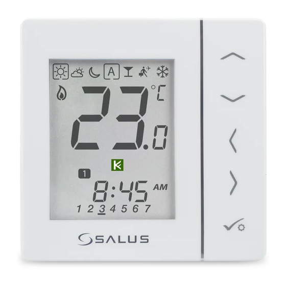
3. Before you start (first power up) 3.1 LCD icon description 2 3 4 5 - Current active mode 8. Manual mode / temp. override 9. Current / set temperature 2. Comfort mode 10. Key lock 3. Standard mode 11. Settings 4. -
Page 17: First Power Up Sequence
3.3 First power up sequence To power on the thermostat you ...display will show all icons... have to connect it to the 230V power supply then..then thermostat will display the After all, the main screen will be software version. displayed. -
Page 18: Work Modes
VS35W/VS35B offers a few work modes. Frame on a given icon indicates which mode is currently active. In manual mode only one temperature level is maintained. VS35W/VS35B follows MASTER thermostat when AUTO mode is active („A” icon) - please refer to 2.5 connection description chapter. Detailed description of work modes is located below: - Frame - means that the work mode is active (the icon of the work mode must be in the center of the frame). -
Page 19: User Settings (Basic Settings)
5. User settings (basic settings) 5.1 Thermostat calibration Thermostat calibration is a function which allows user to recalibrate internal thermostat’s temperature sensor by a given number of degrees (in the range from -3,0 °C to 3,0 °C in 0,5 °C steps). To calibrate thermostat’s temperature sensor please follow steps below: 3 sec. -
Page 20: Heat/Cool Mode Change
5.2 Heat/cool mode change The heating / cooling mode for the thermostat can be changed manually. 3 sec. Hold button for 3 seconds to button to go to Heating/ enter the menu. Cooling choice screen. Thermostat will go back to the main Enter menu by button, choose screen after saving the settings. -
Page 21: Installer Parameters
6. Installer parameters To enter installer parameters please follow steps below. Please refer to parameters table description before any changes. Use buttons to move up or down between all parameters. Every change/selection confirm by button: Hold buttons for 5 to choose seconds to enter the installer mode. - Page 22 Parameter Default Function Description Values Values External sensor used for air Thermostat measures the temperature only on the external sensor or floor temperature measurement (Function is The sensor is used as a protection against overheating the floor active, when d03=1) Span ±0.5°C Cooling mode control method...
-
Page 23: Factory Reset
7. Factory Reset To RESET VS35W/VS35B thermostat to it’s factory default settings please follow steps below: Hold buttons for 5 buttons Press button to confirm. seconds to enter the installer mode. to choose code „47”. Select „del” and confirm choice by Wait few moments to finish factory ...thermostat will display the... -
Page 24: Error Codes
8. Error codes Thermostat constantly monitors the operation of connected sensors. If it detects any failure then following error codes can be displayed. Number of errors Error code View of the display when the Display view when an external external sensor has been selected sensor has been selected as a floor as air temperature measurement sensor (installer parameters D03 = 1... -
Page 25: Cleaning And Maintenance
9. Cleaning and Maintenance The VS35W/VS35B thermostat requires no special maintenance. Periodically, the outer casing can be wiped clean using a dry cloth (please DO NOT use solvents, polishes, detergents or abrasive cleaners, as these can damage the thermostat). There are no user serviceable parts within the unit; any servicing or repairs could only be carried out by Salus Controls or their appointed agents. -
Page 26: Warranty
SALUS Controls warrants that this product will be free from any defect in materials or workmanship, and shall perform in accordance with its specification, for a period of five years from the date of installation. SALUS Controls sole liability for breach of this warranty will be (at its option) to repair or replace the... - Page 28 SALUS Controls is a member of the Computime Group. Maintaining a policy of continuous product development SALUS Controls plc reserve the right to change specification, design and materials of products listed in this brochure without prior notice. Ver. 2 Issued: 09 IX 2020 Soft version: 1.0...
Need help?
Do you have a question about the VS35W and is the answer not in the manual?
Questions and answers