Table of Contents
Advertisement
Quick Links
SERVICE MANUAL
TECHNICAL INFORMATION
FOR SERVICE PERSONNEL ONLY
TYPE
MODEL
POWER SOURCE
TOTAL INPUT
TOTAL AMPERES
COOLING
CAPACITY
TOTAL INPUT
TOTAL AMPERES
HEATING
CAPACITY
DIMENSIONS
(mm)
NET WEIGHT
SPECIFICATIONS AND PARTS ARE SUBJECT TO CHANGE FOR IMPROVEMENT
ROOM AIR CONDITIONER
MAY 2003
RAK-25NH4
RAK-35NH4
RAK-50NH4
RAC-25NH4
RAC-35NH4
RAC-50NH4
RAK-25NH4
1 PHASE, 50 Hz, 220-230V
(W)
695 (155~1,050)
(A)
3.20-3.05
(kW)
2.50 (0.90 ~ 3.00)
(B.T.U./h)
8,540
(W)
900 (115 ~ 1,400)
(A)
4.15-4.00
(kW)
3.50 (0.90 ~ 5.00)
(B.T.U./h)
11,950
W
860
H
285
D
183
(kg)
9.0
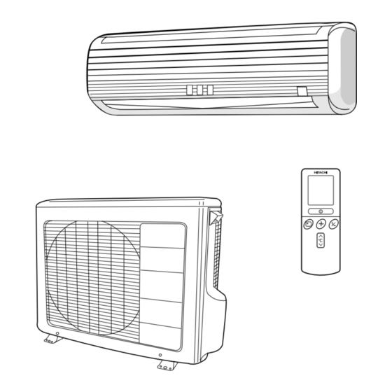
INDOOR UNIT + OUTDOOR UNIT
Refrigeration & Air-Conditioning Division
PM
RAK-25NH4/RAC-25NH4
RAK-35NH4/RAC-35NH4
RAK-50NH4/RAC-50NH4
REFER TO THE FOUNDATION MANUAL
SPECIFICATIONS ------------------------------------------------------------------- 5
HOW TO USE ------------------------------------------------------------------------ 6
Construction And Dimensional Diagram --------------------- 29
Main Parts Component --------------------------------------------------- 31
Wiring Diagram ---------------------------------------------------------------- 33
Circuit Diagram --------------------------------------------------------------- 35
Printed Wiring Board Location Diagram --------------------- 41
Block Diagram ----------------------------------------------------------------- 43
Basic Mode ----------------------------------------------------------------------- 45
Refrigerating Cycle Diagram --------------------------------------- 59
Auto Swing Function ------------------------------------------------------ 61
Description Of Main Circuit Operation ----------------------- 62
SERVICE CALL Q & A ---------------------------------------------------------- 93
Trouble Shooting ----------------------------------------------------------- 96
Parts List And Diagram ------------------------------------------------- 116
DC INVERTER (WALL TYPE)
INDOOR UNIT
RAC-25NH4
RAK-35NH4
1 PHASE, 50 Hz, 220-230V
1,080 (155~1,280)
4.94-4.72
3.50 (0.90 ~ 4.00)
11,950
1,320 (115 ~ 1,920)
6.04-5.77
4.80 (0.90 ~ 6.60)
16,390
750
860
570
285
280
183
38
9.0
NO. 0174E(R)
CONTENTS
OUTDOOR UNIT
INDOOR UNIT
OUTDOOR UNIT
RAK-50NH4
RAC-35NH4
1 PHASE, 50 Hz, 220-230V
1,780 (155~2,200)
8.17-7.82
5.00 (0.90 ~ 5.20)
17,070
1,970 (115 ~ 2,100)
9.04-8.65
6.50 (0.90 ~ 8.10)
22,200
750
860
570
285
280
183
38
9.0
After installation
RAC-50NH4
850
650
298
60
Advertisement
Table of Contents
Troubleshooting

Related Manuals for Hitachi RAK-25NH4


Summary of Contents for Hitachi RAK-25NH4
-
Page 1: Service Manual
NO. 0174E(R) RAK-25NH4/RAC-25NH4 RAK-35NH4/RAC-35NH4 SERVICE MANUAL RAK-50NH4/RAC-50NH4 TECHNICAL INFORMATION REFER TO THE FOUNDATION MANUAL FOR SERVICE PERSONNEL ONLY CONTENTS SPECIFICATIONS ------------------------------------------------------------------- 5 HOW TO USE ------------------------------------------------------------------------ 6 CONSTRUCTION AND DIMENSIONAL DIAGRAM --------------------- 29 MAIN PARTS COMPONENT --------------------------------------------------- 31 WIRING DIAGRAM ---------------------------------------------------------------- 33... - Page 2 SAFETY DURING REPAIR WORK 1. In order to disassemble and repair the unit in question, be sure to disconnect the power cord plug from the power outlet before starting the work. 2. If it is necessary to replace any parts, they should be replaced with respective genuine parts for the unit, and the replacement must be effected in correct manner according to the instructions in the Service Manual of the unit.
- Page 3 WORKING STANDARDS FOR PREVENTING BREAKAGE OF SEMICONDUCTORS 1. Scope The standards provide for items to be generally observed in carrying and handling semiconductors in relative manufacturers during maintenance and handling thereof. (They apply the same to handling of abnormal goods such as rejected goods being returned).
- Page 4 (6) Use a three wire type soldering iron including a grounding wire. Metal plate (of aluminium, stainless steel, etc.) Working table Resistor of 1 M (1/2W) Staple Earth wire Bare copper wire (for body earth) Fig. 3. Grounding of the working table Soldering iron Grounding wire...
- Page 5 CAUTION In quiet operation or stopping the running, slight flowing noise of refrigerant in the refrigerating cycle is heard occasionally, but this noise is not abnormal for the operation. When it thunders near by, it is recommend to stop the operation and to disconnect the power cord plug from the power outlet for safety.
-
Page 6: Specifications
SPECIFICATIONS RAK-25NH4 RAK-35NH4 RAC-25NH4 RAC-35NH4 RAC-50NH4 MODEL RAK-50NH4 FAN MOTOR 40 W PWM DC35V FAN MOTOR CAPACITOR FAN MOTOR PROTECTOR COMPRESSOR JU1012D JU1013D – COMPRESSOR MOTOR CAPACITOR OVERLOAD PROTECTOR OVERHEAT PROTECTOR FUSE (for MICROPROCESSOR) 3.0A POWER RELAY POWER SWITCH TEMPORARY SWITCH... - Page 7 Figure showing the Installation of Indoor and Outdoor unit. The Length of Indoor Unit Power Cord The installation height of indoor unit must be about 2.3m or more in a non public area. 0.9m about 1.6m CAUTION Do not alter the power cord. Direction of Piping above 50mm Be sure to...
-
Page 8: Safety Precaution
SAFETY PRECAUTION Please read the “Safety Precaution” carefully before operating the unit to ensure correct usage of the unit. Pay special attention to signs of “ Warning” and “ Caution”. The “Warning” section contains matters which, if not observed strictly, may cause death or serious injury. The “Caution” section contains matters which may result in serious consequences if not observed properly. - Page 9 PRECAUTIONS DURING OPERATION The product shall be operated under the manufacturer specification and not for any other intended use. Do not attempt to operate the unit with wet hands, this could cause fatal accident. When operating the unit with burning equipments, regularly ventilate the room to avoid oxygen insufficiency.
-
Page 10: Names And Functions Of Each Part
(Refer page 20) Remote controller Send out operation signal to the indoor unit. So as to operate the whole unit. (Refer page 10) MODEL NAME AND DIMENSIONS MODEL WIDTH (mm) HEIGHT (mm) DEPTH (mm) RAK-25NH4, RAK-35NH4, RAK-50NH4 – 8 –... - Page 11 The OPERATION LAMP flashes in the following cases during heating. (1) During preheating For about 2–3 minutes after starting up. HITACHI (2) During defrosting Defrosting will be performed about once an hour when frost forms on the heat exchanger of the outdoor unit, for 5–10 minutes each time.
- Page 12 NAMES AND FUNCTIONS OF REMOTE CONTROL UNIT REMOTE CONTROLLER This controls the operation of the indoor unit. The range of control is about 7 meters. If indoor lighting is controlled electronically, the range of control may be shorter. This unit can be fixed on a wall using the fixture provided. Before fixing it, make sure the indoor unit can be controlled from the remote controller.
-
Page 13: Automatic Operation
VARIOUS FUNCTIONS I Auto Restart Control If there is a power failure, operation will be automatically restarted when the power is resumed with previous operation mode and airflow direction. (As the operation is not stopped by remote controller.) If you intend not to continue the operation when the power is resumed, switch off the power supply. When you switch on the circuit breaker, the operation will be automatically restarted with previous operation mode and airflow direction. -
Page 14: Heating Operation
HEATING OPERATION Use the device for heating when the outdoor temperature is under 21°C. When it is too warm (over 21°C), the heating function may not work in order to protect the device. Press the FUNCTION selector so that the display indicates (HEAT). -
Page 15: Dehumidifying Operation
DEHUMIDIFYING OPERATION Use the device for dehumidifying when the room temperature is over 16°C. When it is under 15°C, the dehumidifying function will not work. Press the FUNCTION selector so that the display indicates (DEHUMIDIFY). ˚ The FAN SPEED is set at LOW automatically. The FAN SPEED button does not work. -
Page 16: Cooling Operation
COOLING OPERATION Use the device for cooling when the outdoor temperature is 22-42°C. If in doors humidity is very high (80%), some dew may form on the air outlet grille of the indoor unit. Press the FUNCTION selector so that the display indicates (COOL). -
Page 17: Fan Operation
FAN OPERATION You can use the device simply as an air circulator. Use this function to dry the interior of the indoor unit at the end of summer. Press the FUNCTION selector so that the display indicates (FAN). Press the (FAN SPEED) button. - Page 18 HOW TO SET THE TIMER Time, Day, Month Set the current month and TIME, DAY, day with the TIMER control After you change the MONTH button. batteries; (current time, day, month) OFF TIMER RESET ON TIMER OFF-Timer Press the (OFF-TIMER) button.
- Page 19 Set the current time with the Press the (TIME) button again. Press the TIMER control button. The time indication starts lighting (TIME) button. instead of flashing. The time indication will disappear automatically in 10 second. To check the current time setting, press the (TIME) button twice.
- Page 20 HOW TO SET THE SLEEP TIMER Set the current time at first if it is not set before (see the pages for setting the current time). Press the (SLEEP) button, and the display changes as shown below. Mode Indication 1 hour 2 hours 3 hours 7 hours...
- Page 21 Explanation of the sleep timer The device will control the FAN SPEED and room temperature automatically so as to be quiet and good for people’s health. You can set the sleep timer to turn off after 1, 2, 3 or 7 hours. The FAN SPEED and room temperature will be controlled as shown below.
- Page 22 ADJUSTING THE AIR DEFLECTOR Adjustment of the conditioned air in the upward and downward directions. The horizontal air deflector is automatically set to the proper angle suitable for each operation. The deflector can be swung RESET up and down continuously and also set to the desired angle using the “...
- Page 23 HOW TO EXCHANGE THE BATTERIES IN THE REMOTE CONTROLLER Remove the cover as shown in the figure and take out the Push and pull to the old batteries. direction of arrow Install the new batteries. The direction of the batteries should match the marks in the case.
- Page 24 THE IDEAL WAYS OF OPERATION Suitable Room Temperature Install curtain or blinds Warning It is possible to Freezing temperature reduce heat is bad for health and a entering the waste of electric power. room through windows. Ventilation Effective Usage Of Timer At night, please use the “OFF or ON timer Caution operation mode”, together with your wake up...
- Page 25 FOR USER’S INFORMATION The Air Conditioner And The Heat Source In The Room Caution If the amount of heat in the room is above the cooling capability of the air conditioner (for example: more people entering the room, using heating equipments and etc.), the preset room temperature cannot be achieved.
- Page 26 ATTACHING THE AIR CLEANSING AND DEODORIZING FILTERS CAUTION Cleaning and maintenance must be carried out only by qualified service personal. Before cleaning, stop operation and switch off the power supply. Open the front panel. Pull up the front panel by holding it at both sides with both hands.
- Page 27 MAINTENANCE CAUTION Cleaning and maintenance must be carried out only by qualified service personal. Before cleaning, stop operation and switch off the power supply. AIR FILTER Clean the air filter, as it removes dust inside the room. In case the air filter is full of dust, the air flow will decrease and the cooling capacity will be reduced.
- Page 28 Washable Front Panel Remove the front panel and wash with clean water. Wash it with a soft sponge. After using neutral detergent, wash thoroughly with clean water. When front panel is not removed, wipe it with a soft dry cloth. Wipe the remote controller thoroughly with a soft dry cloth.
- Page 29 CAUTION Cleaning and maintenance must be carried out only by qualified service personal. Before cleaning, stop operation and switch off the power supply. MAINTENANCE AT BEGINNING OF LONG OFF PERIOD Run the unit by setting the operation mode to (COOL), the temperature to 32°C and the fan speed to HI for about half a day on a fine day, and dry the whole of the unit.
- Page 30 AFTER SALE SERVICE AND WARRANTY WHEN ASKING FOR SERVICE, CHECK THE FOLLOWING POINTS. CONDITION CHECK THE FOLLOWING POINTS Is the fuse all right? Is the voltage extremely high or low? When it does not operate Is the circuit breaker “ON”? Was the air filter cleaned? Does sunlight fall directly on the outdoor unit? Is the air flow of the outdoor unit obstructed?
-
Page 31: Construction And Dimensional Diagram
CONSTRUCTION AND DIMENSIONAL DIAGRAM MODEL RAK-25NH4, RAK-35NH4, RAK-50NH4 Air suction grill Top air suction grill Front panel Mounting plate Cabinet Vertical deflector Discharge grill Horizontal deflector About View from back (Pipe lead-out) 17.5 120.5 When piping is drawn horizontally, exchange the drain... - Page 32 CONSTRUCTION AND DIMENSIONAL DIAGRAM FOR OUTDOOR MODEL RAC-25NH4, RAC-35NH4 MODEL RAC-50NH4 Handle Handle Air suction Air outlet grille Holes for anchor bolt (2-ø12) More than More than Fixing hole Service space Notch for anchor bolt (2-ø12 Notchs) – 30 –...
-
Page 33: Main Parts Component
MAIN PARTS COMPONENT THERMOSTAT Thermostat Specifications MODEL RAK-25NH4, RAK-35NH4, RAK-50NH4 THERMOSTAT MODEL OPERATION MODE COOL HEAT 15.6 (60.1) 20.0 (68.0) INDICATION 15.3 (59.5) 20.7 (69.3) TEMPERATURE 23.6 (74.5) 28.0 (82.4) INDICATION °C (°F) 23.3 (73.9) 28.7 83.7) 31.6 (88.9) 36.0 (96.8) INDICATION 31.3 (88.3) - Page 34 COMPRESSOR MOTOR Compressor Motor Specifications MODEL RAC-25NH4 RAC-35NH4 RAC-50NH4 COMPRESSOR MODEL JU1012D JU1013D PHASE SINGLE RATED VOLTAGE AC 220 ~ 230 V RATED FREQUENCY 50 Hz POLE NUMBER WHITE CONNECTION YELLOW 20°C 2M = 1.05 (68°F) RESISTANCE VALUE 75°C 2M = 1.28 (167°F) WHITE YELLOW...
-
Page 35: Wiring Diagram
WIRING DIAGRAM MODEL RAK-25NH4 / RAC-25NH4 RAK-35NH4 / RAC-35NH4 RAK-50NH4 / RAC-50NH4 OUTDOOR UNIT CN10 COMPRESSOR INDOOR UNIT OUTDOOR TEMPERATURE THERMISTOR WHT YEL RED DEFROST TERMINAL CONNECTING CORD THERMISTOR WHT YEL BOARD FROM OUTDOOR UNIT U V W CN14 CN14... -
Page 36: Circuit Diagram
CIRCUIT DIAGRAM Remote Control Key matrix table Output Input Door open Start/Stop Operation selection Fan speed selection Automatic swing Door shut Start/Stop Automatic swing – – SEG5 SEG20 Door open On timer Hour up Hour down present time • SEG0 SEG19 SEG18 SEG1... - Page 37 CIRCUIT DIAGRAM MODEL RAK-25NH4, RAK-35NH4, RAK-50NH4 – 37 –...
- Page 38 CIRCUIT DIAGRAM MODEL RAC-25NH4/RAC-35NH4/RAC-50NH4 – 39 –...
-
Page 39: Printed Wiring Board Location Diagram
PRINTED WIRING BOARD LOCATION DIAGRAM MODEL RAK-25NH4, RAK-35NH4, RAK-50NH4 MAIN P.W.B. Marking on P.W.B. IVORY HB–098–101A CN14 CN11 L111 C114 REG2 IC402 RES1 IVORY C102 COMPONENT SIDE L101 C101 C821 D101 CN12 C802 IVORY HB-098-101A Q131 C762 ICP3 ZD211 R631... - Page 40 MODEL RAC-25NH4, RAC-35NH4, RAC-50NH4 MAIN P.W.B. Marking on P.W.B – 42 –...
- Page 41 RAK-25NH4 / RAC-25NH4 RAK-35NH4 / RAC-35NH4 RAK-50NH4 / RAC-50NH4 Power source SPM2 1ø, 50Hz, 220~230V Outdoor unit Terminal board Trip signal synthesis circuit Wireless receive LCD wireless circuit Filter. Room temperature Operation. thermistor Timer. Auto sweep motor for Heat exchanger...
- Page 42 BASIC M O D E Operation mode Dehumidifying (dehumidifying operation by the Cooling Heating Auto function select button only, not including that engaged by the dehumidify button) Basic operation of start/stop switch Start Stop Start Stop Start/stop switch Operation tamp Start/stop switch Operation tamp Cancel switch...
- Page 43 Table 1 Mode data file RAK-25NH4 RAK-35NH4 RAK-50NH4 LABEL NAME VALUE –1 –1 –1 WMAX 4500 min 5500 min 6200 min –1 –1 –1 WMAX2 4600 min 5600 min 6250 min –1 –1 –1 WSTD 3250 min 4350 min 5200 min –1...
- Page 44 ∆ Table 2 TCMAX Temperature Calculated difference compressor rpm 1.66 2265 min –1 –1 2435 min 2.33 2600 min –1 2.66 2765 min –1 2935 min –1 –1 3.33 3100 min 3.66 3265 min –1 3435 min –1 –1 4.33 3600 min 4.66 3765 min...
- Page 45 New Cool Rhythm Cooling Sleep Operation Room temperature Final set temperature Minimum Minimum Minimum Minimum (Cooling/dehumidifying set 5min. 5min. Minimum 5min. 5min. 5min. 5min. 5min. 5min. Minimum 5min. 5min. 5min. temperature (+) sleep shift) Final set temperature (Cooling/dehumidifying set temperature (Cooling/dehumidifying set (temperature set by remote 0.5hr...
- Page 46 Delay Notes: (1) If the room temperature is (cooling preset temperature) - (1.33°C) or less after 30 seconds from starting the operation, the operation is done assuming as the preset temperature = (room temperature at the time) - (2°C). (2) The indoor fan is operated in the “Lo” mode. During thermo OFF indoor fan will be OFF for 5 minutes and ON for 1 minute. (3) When the operation is started by the themostat turning ON, the start of the indoor fan is delayed 32 seconds after the start of compressor operation.
- Page 47 ∆ Table 3 TWMAX Basic Heating Operation Temperature Calculated difference compressor rpm –1 1.66 1965 min –1 2135 min 2.33 2300 min –1 Heating set temperature 2.66 2465 min –1 (remote control set temperature (+)) –1 2635 min 3.33 2800 min –1 Dash period 18˚C...
- Page 48 1 min WMIN Notes: The sleep operation starts when the sleep key is pressed. When the sleep key is set, the maximum compressor speed is limited to WSTD+2000/2, and the indoor fan is set to “sleep Lo”. 30 minutes after the sleep key is set, the sleep shift of set temperature starts. The maximum sleep shift of set temperature is 5°C, and the minimum is 12°C.
-
Page 49: Refrigerating Cycle Diagram
REFRIGERATING CYCLE DIAGRAM MODEL RAK-25NH4 / RAC-25NH4 RAK-35NH4 / RAC-35NH4 COOLING, DEHUMIDIFYING, DEFROSTING OUTDOOR UNIT INDOOR UNIT SERVICE VALVE (3/8) SINGLE-ENDED UNION (3/8) SUCTION TANK REVERSING VALVE ELECTRIC EXPANSION VALVE SERVICE VALVE (1/4) SINGLE-ENDED STRAINER UNION (1/4) STRAINER CHARGING PIPE... - Page 50 REFRIGERATING CYCLE DIAGRAM MODEL RAK-50NH4 / RAC-50NH4 COOLING, DEHUMIDIFYING, DEFROSTING OUTDOOR UNIT SERVICE VALVE INDOOR UNIT (1/2) SINGLE-ENDED UNION (1/2) SUCTION TANK REVERSING VALVE ELECTRIC EXPANSION VALVE SERVICE VALVE (1/4) STRAINER SINGLE-ENDED UNION (1/4) STRAINER HEATING SERVICE VALVE OUTDOOR UNIT INDOOR UNIT (1/2) SINGLE-ENDED...
- Page 51 – 61 –...
-
Page 52: Description Of Main Circuit Operation
DESCRIPTION OF MAIN CIRCUIT OPERATION MODEL RAK-25NH4, RAK-35NH4, RAK-50NH4 1. Reset Circuit NORMAL : HI RESET : LO Microcomputer R522 IC521 Fig. 1-1 Voltage 5.0V Voltage supply to of IC521 Reset enter at 4.2V Reset release at 4.4V voltage 5.0V... - Page 53 2. Receiver Circuit R201 R611 RECEIVER I/P Microcomputer Fig. 2-1 The light receiver unit receives the infrared signal from the wireless remote control. The receiver amplifies and shapes the signal and outputs it. 3. Buzzer Circuit R219 Microcomputer Buzzer output Q722 Fig.
- Page 54 4. Auto Sweep Motor Circuit Auto sweep motor for horizontal air defectors IC711 Rotor Microcomputer Fig.4-1 Fig. 4-1 shows the Auto sweep motor drive circuit; the signals shown in Fig.4-2 are output from pins – of microcomputer. Horizontal air Microcomputer pins Step width deflectors: 10ms.
- Page 55 5. Room Temperature Thermistor Circuit Fig. 5-1 shows the room temperature The voltage at depends on the room thermistor circuit. temperature as shown in Fig. 5-2. Room Microcomputer temperature thermistor R305 Room temp. input C302 R301 Fig. 5-1 Room temperature (˚C) Fig.
- Page 56 7. Initial Setting Circuit (IC401) When power is supplied, the microcomputer reads the data in IC401 or IC402 (E PROM) and sets the preheating activation value and the rating and maximum speed of the compressor, etc. to their initial values. Data of self-diagnosis mode is stored in IC401 or IC402;...
- Page 57 Model RAC-25NH4, RAC-35NH4, RAC-50NH4 1. Power Circuit REACTOR SPM2 DIODE TERMINAL STACK 1 BOARD COIL POWER RELAY 25A FUSE NF COIL1 (D25VB60) SURGE- TB10 ABSORBER R007 R008 TB11 ICP RELAY TB12 C009 L001 L002 DIODE STACK 2 (RC2) R002 C014 C012 C007 C015...
- Page 58 (3) Smoothing capacitor (C501, C502, C503) This smoothes (averages) the voltage rectified by the diode stacks. <Notes> Smoothing capacitor C501 is not available for model RAC-25NH4 and RAC-35NH4. Smoothing Capacitors SPM2 Fig. 1-2 Be careful to avoid an electric shock as a high voltage is generated.
- Page 59 2. Indoor/Outdoor Interface Circuit The interface circuit superimposes an interface signal on the DC 35V line supplied from the outdoor unit to perform communications between indoor and outdoor units. This circuit consists of a transmiting circuit which superimposes an interface signal transmit from the microcomputer on the DC 35V line and a transmiting circuit which detects the interface signal on the DC 35V line and outputs it to the microcomputer.
- Page 60 Fig. 2-1 shows the interface circuit used for the indoor and outdoor microcomputers to communicate with each other. R805 R813 R803 IC801 L801 R812 R810 IF transmit Q803 Q802 output (SDO) R804 R806 R811 C803 C802 C801 C804 MICROCOMPUTER Q801 R824 R826 R822...
- Page 61 0.7V Outdoor HIC Indoor microcomputer DC 35V line 100ms. 33ms. Leader 1 frame Fig. 2-2 Voltages Waveforms of indoor / Outdoor Microcomputers (Outdoor to Indoor Communications) Outdoor HIC Indoor microcomputer DC 35V line 4.95ms. 33ms. Transmit / receive 1 frame switching time Fig.
- Page 62 – 72 –...
- Page 63 Compressor minimum rotation speed (4 MSB) Compressor minimum rotation speed (3) Compressor minimum rotation speed (2) Compressor minimum rotation speed (1) Compressor minimum rotation speed (0 LSB) Fan-7-step request OVL up 15/20(A) Actual compressor rotation speed (5 MSB) Compressor command speed (7 MSB) Actual compressor rotation speed (4) Compressor command speed (6) Actual compressor rotation speed (3)
- Page 64 3. Power Module Circuit – 74 –...
- Page 65 DC 260-360V is input to system power module and system power module switches power supply current according to rotation position of magnet rotor. The switching order is as shown in Fig. 3-2. At point E: U + is ON, V – is ON (circuit in Fig. 3-1) At point F: U + is chopped (OFF), V –...
-
Page 66: Trouble Shooting
System Power Module 2 260V-360V DC compressor U coil motor V coil — — — W coil DC current (Id) detection resistor Fig. 3-4 Power module circuit (U + is ON, V – is ON) Since current flows at point only when U+ transistor is ON, the current waveform at point becomes intermittent waveform as shown in Fig. - Page 67 4. Power Circuit for P.W.B. Fig. 4-1 shows the power circuit for P.W.B. and waveform at each point. Switching transformer (T1) C909 D907 Diode stack 2 R914 C910 (RC2) R902 I/F0V D908 L902 R915 R901 C901 R916 C911 D911 FM–15V R917 D909 R002...
- Page 68 (2) During ON The drain current at IC901 increases linearly. During this period, the gate voltage and current become constant because of the saturation characteristics of the transformer. (3) Shifting from ON to OFF This circuit applies a negative feedback signal from the 12V output. When the voltage across C919 reaches the specified value, REG2 turns on and current flows to PQ2 1-2.
- Page 69 5. Reversing valve control circuit I/F 35V Reversing FUSE RESISTOR valve D702 PQ701 R703 Q701 Q705 R701 R219 R702 DC voltmeter or tester I/F 0V Fig. 5 – 1 Reversing valve control circuit can switch reversing valve ON/OFF according to instruction from indoor microcomputer depending on the operation condition shows in Table 5-1.
- Page 70 6. Rotor magnetic pole position detection circuit System power module DC brushless motor for compressor 36 33 34 35 47 +12V C608 R604 C605 R605 C606 R606 R607 C607 No power Upper arm No power Lower arm No power supplied supplied supplied Induced voltage...
- Page 71 7. Drive Circuit Fig. 7-1 shows the drive circuit. The circuits for U phase, V phase and W phase have the same Configuration. – 81 –...
- Page 72 [Low speed rotation mode] Fig. 7-2 [High speed rotation mode] Fig. 7-3 – 82 –...
- Page 73 8. HIC and Peripheral Circuits Fig. 8-1 shows the micro computer and its peripheral circuits, Table 8-1, the basic operations of each circuit block, and Fig. 8-2, the system configuration. Detection Resistor DC Current SPM2 – HIC Direct Current DC260-380V SPM2 CN14 CN13...
- Page 74 Reset Voltage Reset circuit Chopper Chopper Drive signal signal signal Drive Compressor Circuit Over-load external motor setting circuit DC 260V -360V Power module IP signal Peak current Current cut off circuit level Current amplified circuit Detection resistor DC current Fig. 8-2 The following describes the operations of each circuit in detail.
- Page 75 (2) Overload control circuit (OVL control circuit) Overload control is to decrease the speed of the compressor and reduce the load when the load on the air conditioner increases to an overload state, in order to protect the compressor, electronic components and power breaker.
- Page 76 Detection Resistor Direct Current DC Current DC 260-380V SPM2 CN14 CN13 MAIN P.W.B. C205 – R245 R248 Microcomputer R222 D104 R005 R221 C218 Fig. 8-6 Voltage at microcomputer pin Rotation speed of compressor Commanded rotation speed Actual rotation speed Deceleration Acceleration Deceleration Acceleration...
- Page 77 R500, R253, detect the DC voltage at the power circuit. The microcomputer receives a DC voltage (260- 380V) via HIC and applies correction to the overload set value so the DC current is low (high) when the DC voltage is high (low). (Since the load level is indicated by the DC voltage multiplied by DC current, R247, R248, R249 are provided to perform the same overload judgement even when the voltage varies.) Amplification : low...
- Page 78 9. Temperature Detection Circuit O.H. thermistor Normal 2.7V or less Over heat 2.7V or more Reset 2.3V or less O.H. Microcomputer DEF. thermistor Normal 2.4V or more Over heat 2.4V or less Reset 2.9V or more DEF. Outdoor temperature thermistor Refer to the table 10-1 Outdoor CN10...
- Page 79 10. Reset Circuit Main P.W.B Microcomputer R284 R289 – R252 JW10 RESET IC5 (1/2) R288 Fig. 10-1 The reset circuit initializes the microcomputer program when Power is “ON” or “OFF”. Low voltage at pin resets the microcomputer, and HI activates the microcomputer. Fig.
- Page 80 11. Outdoor DC Fan Motor control circuit. System power module Power supply for DC fan motor from smoothing capacitor in system power module RC Filter CN12 Main P.W.B 2A-FUSE Motor coil C101 FM-15V FM-15V R107 Q101 PWM control voltage D101 FG Pulse R101 R102...
- Page 81 < Reference > When operation stop with LD301 blinks 12 times, it may be caused by faulty DC fan motor. In this case, please check CN6 and CN12 connection first. It makes Fan Motor Lock also if those connectors are in misconnection. DC Fan Motor has broken when 2A Fuse was burned.
- Page 82 12. Power Factor Control Circuit Power factor is controlled to almost 100%. (Effective use of power) With IC in ACT module, control is performed so that input current waveform will be similar to waveform of input voltage I (input current) input voltage V (input voltage) Effective...
- Page 83 SERVICE CALL Q & A Model RAK-25NH4 / RAC-25NH4 RAK-35NH4 / RAC-35NH4 RAK-50NH4 / RAC-50NH4 COOLING MODE The compressor has Check if the indoor heat If the air conditioner operates stopped suddenly during exchanger is frosted. in cooling mode when it is cooling operation.
- Page 84 AUTO FRESH DEFROSTING Auto Fresh Defrosting is carried out : the After the ON/OFF button is pressed system checks the outdoor heat exchanger to stop heating, the outdoor unit is and defrosts it as necessary before stopping still working with the OPERATION operation.
- Page 85 OTHERS The heat exchanger temperature The indoor fan varies among This is because the cool is sensed in the auto speed mode. high air flow, low air flow and wind prevention function When the temperature is low, the breeze in the auto fan speed is operating, and does fan speed varies among high air mode.
- Page 86 TROUBLE SHOOTING Model RAK-25NH4 / RAC-25NH4 RAK-35NH4 / RAC-35NH4 RAK-50NH4 / RAC-50NH4 PRECAUTIONS FOR CHECKING System power module 2 Power source DANGER – – – 1. Remember that the Compressor motor 0V line is biased to 155-170V in (0V) reference to the ground level.
- Page 87 DISCHARGE PROCEDURE AND POWER SHUT OFF METHOD FOR POWER CIRCUIT Caution Voltage of about 300-330V is charged between both ends of smoothing capacitors During continuity check for each part of circuit in indoor unit electrical parts, disconnect red/gray WARNING lead wire connected from diode stack to system power module (SPM2) to prevent secondary trouble.
- Page 88 CHECKING THE INDOOR/OUTDOOR UNIT ELECTRICAL PARTS AND REFRIGERATING CYCLE Model RAK-25NH4 / RAC-25NH4 RAK-35NH4 / RAC-35NH4 RAK-50NH4 / RAC-50NH4 Timer lamp See “Troubleshooting when the timer lamp Does the timer lamp on the indoor unit blink? blinks”. Remove the terminal cover and check the voltage...
- Page 89 TROUBLESHOOTING WHEN TIMER LAMP BLINKS. Model RAK-25NH4, RAK-35NH4, RAK-50NH4 Perform troubleshooting according to the number of times the indoor timer lamp and outdoor LD301 blink. SELF-DIAGNOSIS LIGHTING MODE Model: RAK-25NH4, RAK-35NH4, RAK-50NH4 Blinking of Timer lamp Reason for indication Possible cause...
- Page 90 SELF-DIAGNOSIS LIGHTING MODE MODEL: RAC-25NH4, RAC-35NH4 & RAC-50NH4 – 100 –...
- Page 91 CHECKING INDOOR UNIT ELECTRICAL PARTS 1. Power does not come on (no operation) Is AC 220-240V AC being generated Is DC 35V being generated between Check AC outlet and breaker, and between terminals L and N on the terminals C and D on the terminal repair any defective part.
- Page 92 2. Outdoor unit does not operate (but receives remote infrared signal) Set to room temperature 16°C in the cooling mode or to 32°C in the heating mode, and press the start/stop button. Remove the outdoor unit cover and electrical parts cover, and check self- Check the room temperature diagnosis lamp LD301.
- Page 93 3. Only indoor fan does not operate (other is normal) Can the fan be stopped by The microcomputer fan PWM Replace the microcomputer. remote control? output (pin) is “Hi” Replace the indoor fan motor. Replace the microcomputer. Perform final operation check. 4.
- Page 94 6. Check the main P.W.B (power circuit) Replace ICP2. Check if Is DC 35V being output Is ICP2 normal? shorting has occurred in fan between cathode and Normal if it is less than 1Ω. motor circuit and 35V anode of D101? Blown (open) if it is 1Ω...
-
Page 95: Checking The Remote Controller
CHECKING THE REMOTE CONTROLLER Is battery polarity correct? Install the battery in the correct polarity. Is the battery check sign + – Replace the battery. flashing? Turn on an AM radio, bring the remote control switch within 15 cm of the radio, and press the ON/OFF button. - Page 96 CHECKING THE OUTDOOR UNIT ELECTRICAL PARTS MODEL RAC-25NH4, RAC-35NH4, RAC-50NH4 – 106 –...
- Page 97 – 107 –...
- Page 98 – 108 –...
- Page 99 – 109 –...
- Page 100 – 110 –...
- Page 101 POWER CIRCUIT Phenomenon 1 <Rotation speed does not increase> Recheck cord, etc. of the Is the DC voltage at least 350V? system power module. If they are disconnected, connect them securely. Is the OVL lamp lit? If the lamp is lit, it does not If abnormality continues, replace the system indicate fault, but the unit...
- Page 102 (JUDGING BETWEEN GAS LEAKAGE AND CHECKING THE REFRIGERATING CYCLE COMPRESSOR DEFECTIVE) 1. Troubleshooting procedure (No operation, No heating, No cooling) Lighting mode Blinks Blinks Blinks Blinks Blinks Blinks Connect U,V,W phase leads to the Self- 2 times 3 times 4 times 5 times 6 times 8times...
- Page 103 HOW TO CHECK SYSTEM POWER MODULE Checking system power module using tester Set tester to resistance range (X 100) If indicator does not swing in the following conductivity check, the system power module is normal. (In case of digital tester, since built-in battery is set in reverse direction, + and – terminals are reversed.) CAUTION If inner circuit of system power module is disconnected (open), the indicator of tester will not swing and this may assumed as normal.
-
Page 104: How To Operate The Outdoor Unit Independently
HOW TO OPERATE USING THE SERVICE SWITCH THE OUTDOOR UNIT MODEL RAC-25NH4, RAC-35NH4, RAC-50NH4 1. Turn off the power supply to outdoor unit and then turn on again. 2. Remove the electrical box cover. LD303 (red) will light and the unit will operate in the forced cooling mode at this time. Never operate the unit for more than 5 minutes. - Page 105 SYSTEM POWER MODULE DIAGNOSIS Circuit diagram of Collector the device (excepting the reflux diode) BASE Emitter Circuit diagram of the module – Terminals symbol mark of the module See next page for measuring value using tester – L2 L1 – 115 –...
- Page 106 PARTS LIST AND DIAGRAM INDOOR UNIT MODEL : RAK-25NH4, RAK-35NH4, RAK-50NH4 – 116 –...
- Page 107 MODEL RAK-25NH4 PART N0. Q’TY / UNIT PARTS NAME RAK-25NH4 PMRAK-25NH4 CABINET PMRAS-40CNH2 MOUNTING PLATE PMRAK-25NH4 FAN MOTOR PMRAS-40CNH2 TANGENTIAL AIR FLOW FAN PMRAS-25CNH2 P-BEARING ASSEMBLY PMRAS-10C7M FAN MOTOR SUPPORT PMRAK-25NH4 CYCLE ASSY PMRAS-51CHA1 FAN COVER PMRAS-18CP5 PIPE SUPPORT PMRAS-10C7M...
- Page 108 MODEL RAK-35NH4 PART N0. Q’TY / UNIT PARTS NAME RAK-35NH4 PMRAK-25NH4 CABINET PMRAS-40CNH2 MOUNTING PLATE PMRAK-25NH4 FAN MOTOR PMRAS-40CNH2 TANGENTIAL AIR FLOW FAN PMRAS-25CNH2 P-BEARING ASSEMBLY PMRAS-10C7M FAN MOTOR SUPPORT PMRAK-25NH4 CYCLE ASSEMBLY PMRAS-51CHA1 FAN COVER PMRAS-18CP5 PIPE SUPPORT PMRAS-10C7M DRAIN PAN ASSSEMBLY PMRAS-10C6M AUTO SWEEP MOTOR...
- Page 109 MODEL RAK-50NH4 PART N0. Q’TY / UNIT PARTS NAME RAK-50NH4 PMRAK-25NH4 CABINET PMRAS-40CNH2 MOUNTING PLATE PMRAK-25NH4 FAN MOTOR PMRAS-40CNH2 TANGENTIAL AIR FLOW FAN PMRAS-25CNH2 P-BEARING ASSEMBLY PMRAS-10C7M FAN MOTOR SUPPORT PMRAK-50NH4 CYCLE ASSY PMRAS-51CHA1 FAN COVER PMRAS-18CP5 PIPE SUPPORT PMRAS-10C7M DRAIN PAN ASSSEMBLY PMRAS-10C6M AUTO SWEEP MOTOR...
-
Page 110: Outdoor Unit
OUTDOOR UNIT MODEL : RAC-25NH4, RAC-35NH4 – 120 –... - Page 111 MODEL RAC-25NH4 PART N0. Q’TY / UNIT PARTS NAME RAC-25NH4 PMRAC-25NH4 BASE PMRAC-25NH4 COMPRESSOR KPNT1 PUSH NUT RAC-2226HV COMPRESSOR RUBBER PMRAC-25NH4 CONDENSER PMRAC-25NH4 REVERSING VALVE PMRAC-25NH4 ELECTRICAL EXPANSION COIL PMRAC-25NH4 VALVE (2S) PMRAC-25NH4 VALVE (4S) PMRAC-40CNH2 THERMISTOR (OH) PMRAC-25NH4 OVERHEAT THERMISTOR SUPPORT PMRAC-25NH4 OVERLOAD RELAY COVER PMRAC-40CNH2...
- Page 112 MODEL RAC-35NH4 PART N0. Q’TY / UNIT PARTS NAME RAC-35NH4 PMRAC-25NH4 BASE PMRAC-25NH4 COMPRESSOR KPNT1 PUSH NUT RAC-2226HV COMPRESSOR RUBBER PMRAC-25NH4 CONDENSER PMRAC-25NH4 REVERSING VALVE PMRAC-25NH4 ELECTRICAL EXPANSION COIL PMRAC-25NH4 VALVE (2S) PMRAC-25NH4 VALVE (4S) PMRAC-40CNH2 THERMISTOR (OH) PMRAC-25NH4 OVERHEAT THERMISTOR SUPPORT PMRAC-25NH4 OVERLOAD RELAY COVER PMRAC-40CNH2...
-
Page 113: Parts List And Diagram
PARTS LIST AND DIAGRAM OUTDOOR UNIT MODEL : RAC-50NH4 – 123 –... - Page 114 MODEL RAC-50NH4 PART N0. Q’TY / UNIT PARTS NAME RAC-50NH4 PMRAC-50NH4 BASE PMRAC-50NH4 COMPRESSOR KPNT1 PUSH NUT RAC-2226HV COMPRESSOR RUBBER PMRAC-50NH4 CONDENSER PMRAC-25NH4 REVERSING VALVE PMRAC-25NH4 ELECTRICAL EXPANSION COIL PMRAC-50NH4 VALVE (2S) PMRAC-50NH4 VALVE (4S) PMRAC-40CNH2 THERMISTOR (OH) PMRAC-25NH4 OVERHEAT THERMISTOR SUPPORT PMRAC-25NH4 OVERLOAD RELAY COVER PMRAC-40CNH2...
- Page 115 HITACHI RAK-25NH4/RAC-25NH4 PM NO. 0174E RAK-35NH4/RAC-35NH4 Printed in Malaysia RAK-50NH4/RAC-50NH4...
Need help?
Do you have a question about the RAK-25NH4 and is the answer not in the manual?
Questions and answers