Table of Contents
Advertisement
Advertisement
Table of Contents

Related Manuals for HYT tc-600


Summary of Contents for HYT tc-600
-
Page 2: Table Of Contents
Exploded View… … … … … … … … … … … … … … … … … … … … … … … … … . TC-600 Parts List 2… … … … … … … … … … … … … … … … … … … … … … …... -
Page 3: Revision History
TC-600 Service Manual Revision History Material No. Date of Issue Changes 8130060000100 Initial Release 1. High frequency amplifier tube, mixer diode and parts list 1. 8130060000110 2. Parts list 2. 1. Audio power amplifier, APC circuit and parts list 1. -
Page 4: Radio Overview
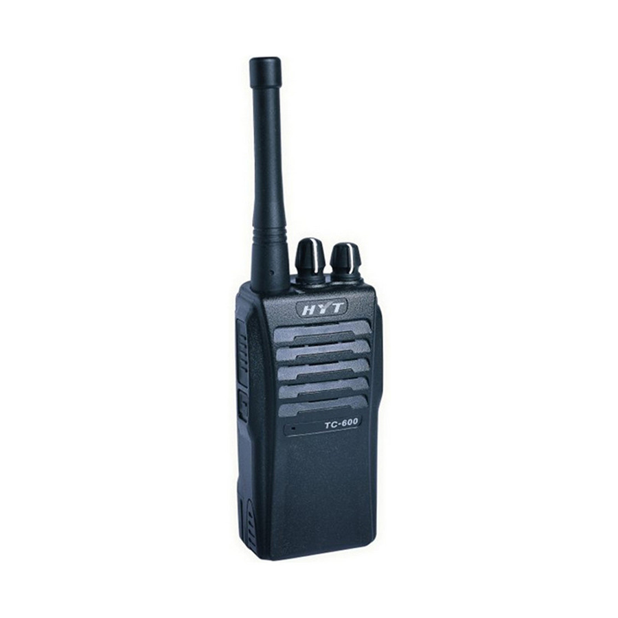
TC-600 Service Manual Radio Overview Antenna Helical antenna with a threaded connector. It is used to transmit/receive signals. 2. LED Indicator The light will glow red during transmission and glow green during receiving. During transmission, the light flashes red when the battery voltage is low. - Page 5 TC-600 Service Manual to program the radio via the programming software. 10. Battery 11. Belt Clip Used to clip the radio on your belt. 12. Battery Latch Used to fasten and remove the battery. 13. Battery Charging Piece Insert the battery into the charger; connect the battery charging piece with those on the charger to...
-
Page 6: Software Specifications
TC-600 Service Manual Software Specifications Radio Feature Description 1. Use the Channel Selector Knob to choose from 15+1(Scan) channels 2. Monitor 3. CTCSS/CDCSS Encode & Decode CTCSS: 38 groups CDCSS: 83 groups 4. Wideband (25KHz) / Narrowband (12.5KHz) 5. Channel Scan (priority channel and revert channel available) 6. - Page 7 1. User Mode User Mode is for conventional communication operation. Disconnect the two SELF points and then turn the power on, the radio enters User Mode. (Refer to “ TC-600 Owner’ s Manual” for detailed operation description.) 2. Model Set Mode Select MS1 according to the radio model.
- Page 8 TC-600 Service Manual ● Short out the two SELF points. ● Turn on the power and rotate the Channel Selector Knob to CH7. ● Press PTT while holding down Function Key. ● After reset, turn off the power and disconnect the two SELF points. The radio operates at the preset frequency after restart.
- Page 9 TC-600 Service Manual 5. Manual Adjust Mode If Manual Adjust Mode is enabled, turn on the power while holding down PTT and Function Key simultaneously, the radio enters Manual Adjust Mode in 2 seconds. Choose the adjusting items by turning the channel selector knob to CH1-CH7; use PTT/Function Key to adjust upwards/downwards (Note: MIC jack shouldn’...
- Page 10 TC-600 Service Manual a) If the two SELF points are disconnected, press Function key again, the radio starts user wired clone and red LED flashes; when cloning is completed, red LED goes out. b) If the two SELF points are short out, press Function key again, the radio starts factory wired clone...
- Page 11 TC-600 Service Manual Initial Data Table 1CH (Center) 2CH (Low) 3CH (High) 9-16CH Frequency Model (MHz) (MHz) (MHz) (MHz) (MHz) (MHz) (MHz) (MHz) (MHz) (MHz) (MHz) (MHz) (MHz) (MHz) 150.000~173.995 +45.050 162.000 162.100 150.000 150.100 173.975 173.900 162.500 162.550 162.600 162.550...
-
Page 12: Circuit Description
TC-600 Service Manual Circuit Description 1. Frequency Configuration The receiver utilizes double conversion superheterodyne. The first IF is 45.050MHz and the second is 455 KHz. The first local oscillator signal is supplied from PLL circuit. Frequency needed in the transmitter is supplied from PLL circuit. Figure 1 shows the frequency configuration. - Page 13 TC-600 Service Manual Figure 2 Receiver Section Configuration 2) The First Mixer The signal from RF amplifier is mixed with the first local oscillator signal from PLL frequency synthesizer in the first mixer (Q23) to generate a 45.050MHz first IF signal. The first IF signal is then fed through two monolithic crystal filters (XF1) to remove spurious signals from adjacent channels.
- Page 14 TC-600 Service Manual FM IF IC1 AF/PF AMP IF AMP 39 40 IC11 Figure 3 Audio Amplifier and Squelch Circuit 6) Receive Signaling CTCSS/CDCSS Over 300Hz audio frequencies of the signal output from IF chip is cut off by a low pass filter. The resulting signal enters the microprocessor IC11.
- Page 15 TC-600 Service Manual low-pass filter and passed to the VCO to control the oscillator frequency. (See Figure 4) Figure 4 PLL Circuit 2) VCO The operating frequency is generated by Q16 in transmit mode and by Q8 in receive mode.
- Page 16 TC-600 Service Manual Figure 5 Transmit CTCSS 3) DTMF/2-Tone Encoder DTMF/2-Tone signalings are generated by IC11 and outputted in parallel by Pin 48-51. The output signal is reshaped by resistor array CP7-CP10, then sent to IC3 (1/4) for amplification, and filtered by active LPF consisting of Q25, Q24 and other components to eliminate the corresponding HF emission before being passed to TX VCO for modulation.
-
Page 17: Cpu Pins
TC-600 Service Manual CPU Pins Pin No. Pin Name Description CTCSS/CDCSS input BUSY Busy signal input BATT Battery voltage detect TIBI CTCSS/CDCSS external circuit center point input SAVE Battery save control H: OFF L: ON TXLow TX power control H: Low power L: High power... - Page 18 TC-600 Service Manual AF_PWR AF power supply control CTDCSS5 CTDCSS4 CTDCSS3 CTCSS/CDCSS code output CTDCSS2 CTDCSS1 CTDCSS0 WNTC Wideband/narrowband L: W H: N DTMF/2ToneOut5 DTMF/2ToneOut4 DTMF/2ToneOut3 DTMF/2-Tone code output DTMF/2ToneOut2 DTMF/2ToneOut1 DTMF/2ToneOut0 54-70 Power input: 5V Vref A-D conversion reference voltage...
-
Page 19: Tc-600 Vhf Parts List 1
TC-600 Service Manual TC-600 VHF Parts List 1 150-174MHz Material No. Description Qty Ref. No. Address 3001053330010 Chip resistor 0402 33KΩ J 1/16W(RoHS) R629 3001060000000 Chip resistor 0603 0Ω J 1/10W(RoHS) 3001060000000 Chip resistor 0603 0Ω J 1/10W(RoHS) 3001060000000 Chip resistor 0603 0Ω J 1/10W(RoHS) R107 3001060000000 Chip resistor 0603 0Ω... - Page 20 TC-600 Service Manual Material No. Description Qty Ref. No. Address 3001061020010 Chip resistor 0603 1KΩ J 1/10W(RoHS) 3001061020010 Chip resistor 0603 1KΩ J 1/10W(RoHS) 3001061020010 Chip resistor 0603 1KΩ J 1/10W(RoHS) 3001061020010 Chip resistor 0603 1KΩ J 1/10W(RoHS) 3001061020010 Chip resistor 0603 1KΩ J 1/10W(RoHS) 3001061020010 Chip resistor 0603 1KΩ...
- Page 21 TC-600 Service Manual Material No. Description Qty Ref. No. Address 3001061510000 Chip resistor 0603 150Ω J 1/10W(RoHS) 3001061520000 Chip resistor 0603 1.5KΩ J 1/10W(RoHS) 3001061520000 Chip resistor 0603 1.5KΩ J 1/10W(RoHS) 3001061520000 Chip resistor 0603 1.5KΩ J 1/10W(RoHS) 3001061530010 Chip resistor 0603 15KΩ J 1/10W(RoHS) R161 3001061530010 Chip resistor 0603 15KΩ...
- Page 22 TC-600 Service Manual Material No. Description Qty Ref. No. Address 3001063320000 Chip resistor 0603 3.3KΩ J 1/10W(RoHS) 3001063320000 Chip resistor 0603 3.3KΩ J 1/10W(RoHS) 3001063320000 Chip resistor 0603 3.3KΩ J 1/10W(RoHS) 3001063320000 Chip resistor 0603 3.3KΩ J 1/10W(RoHS) 3001063320000 Chip resistor 0603 3.3KΩ J 1/10W(RoHS) 3001063320000 Chip resistor 0603 3.3KΩ...
- Page 23 TC-600 Service Manual Material No. Description Qty Ref. No. Address 3001064730000 Chip resistor 0603 47KΩ J 1/10W(RoHS) R607 3001064730000 Chip resistor 0603 47KΩ J 1/10W(RoHS) R608 3001064730000 Chip resistor 0603 47KΩ J 1/10W(RoHS) R609 3001064730000 Chip resistor 0603 47KΩ J 1/10W(RoHS) R610 3001064730000 Chip resistor 0603 47KΩ...
- Page 24 TC-600 Service Manual Material No. Description Qty Ref. No. Address 3005064720000 Resistor array 0603 4.7KΩ*2 J 1/16W (RoHS) 3005064720010 Resistor array 0603 4.7KΩ*4 J 1/16W*4 (RoHS) 3005064720010 Resistor array 0603 4.7KΩ*4 J 1/16W*4 (RoHS) 3101050400010 Chip capacitor 0402 4PF B 50V (RoHS)
- Page 25 TC-600 Service Manual Material No. Description Ref. No. Address 3101051020010 Chip capacitor 0402 1000PF K 50V (RoHS) 262 3101051020010 Chip capacitor 0402 1000PF K 50V (RoHS) 3101051020010 Chip capacitor 0402 1000PF K 50V (RoHS) 264 3101051020010 Chip capacitor 0402 1000PF K 50V (RoHS)
- Page 26 TC-600 Service Manual Material No. Description Qty Ref. No. Address 3101051820000 Chip capacitor 0402 1800PF K 50V(RoHS) C172 3101052200010 Chip capacitor 0402 22PF J 50V (RoHS) 3101052210010 Chip capacitor 0402 220PF K 50V (RoHS) 3101052210010 Chip capacitor 0402 220PF K 50V (RoHS)
- Page 27 TC-600 Service Manual Material No. Description Qty Ref. No. Address 3101054710010 Chip capacitor 0402 470PF K 50V (RoHS) C217 3101054710010 Chip capacitor 0402 470PF K 50V (RoHS) C218 3101054710010 Chip capacitor 0402 470PF K 50V (RoHS) 3101054710010 Chip capacitor 0402 470PF K 50V (RoHS)
- Page 28 TC-600 Service Manual Material No. Description Qty Ref. No. Address 3102992000000 Trimmer capacitor 3.2*2.5*1.25mm 6P 55V (RoHS) 3102992000040 Trimmer capacitor 3.2*2.5*1.25mm 10P 55V (RoHS) 3102992000040 Trimmer capacitor 3.2*2.5*1.25mm 10P 55V (RoHS) 3102992000040 Trimmer capacitor 3.2*2.5*1.25mm 10P 55V (RoHS) 3102992000040 Trimmer capacitor 3.2*2.5*1.25mm 10P 55V (RoHS) 3102992000040 Trimmer capacitor 3.2*2.5*1.25mm 10P 55V (RoHS)
- Page 29 TC-600 Service Manual Material No. Description Qty Ref. No. Address 3215107180000 Bobbin inductor 0805 18nH (RoHS) 3215107390000 Bobbin inductor 0805 39nH (RoHS) 3215107680000 Bobbin inductor 0805 68nH (RoHS) 3215107680000 Bobbin inductor 0805 68nH (RoHS) 3215107680000 Bobbin inductor 0805 68nH (RoHS) 3215107680000 Bobbin inductor 0805 68nH (RoHS) 3221506601000 Chip ferrite bead 0603 600Ω±...
- Page 30 TC-600 Service Manual Material No. Description Qty Ref. No. Address 3403008000010 Transistor DTC114EE(TL) (RoHS) 3403008000010 Transistor DTC114EE(TL) (RoHS) 3403008000010 Transistor DTC114EE(TL) (RoHS) 3403008000070 Transistor DTC144EE(TL) (RoHS) 3403008000070 Transistor DTC144EE(TL) (RoHS) 3403009000010 Transistor UMG3N(N-TR) (RoHS) 3403009000010 Transistor UMG3N(N-TR) (RoHS) 3406001000090 Transistor 2SC4988FRTR-E (RoHS)
- Page 31 TC-600 Service Manual Material No. Description Qty Ref. No. Address 3101051000020 Chip capacitor 0402 10PF J 50V (RoHS) C107 3101051000020 Chip capacitor 0402 10PF J 50V (RoHS) C144 3101051000020 Chip capacitor 0402 10PF J 50V (RoHS) C187 3101052000020 Chip capacitor 0402 20PF J 50V (RoHS)
-
Page 32: Tc-600 Uhf Parts List 1
TC-600 Service Manual TC-600 UHF Parts List 1 400-420MHz Material No. Description Qty Ref. No. Address 3001051030000 Chip resistor 0402 10KΩ J 1/16W(RoHS) C254 3001051040010 Chip resistor 0402 100KΩ J 1/16W(RoHS) R623 3001051040010 Chip resistor 0402 100KΩ J 1/16W(RoHS) R624 3001056830000 Chip resistor 0402 68KΩ... - Page 33 TC-600 Service Manual Material No. Description Qty Ref. No. Address 3001061020010 Chip resistor 0603 1KΩ J 1/10W(RoHS) 3001061020010 Chip resistor 0603 1KΩ J 1/10W(RoHS) 3001061020010 Chip resistor 0603 1KΩ J 1/10W(RoHS) 3001061020010 Chip resistor 0603 1KΩ J 1/10W(RoHS) 3001061020010 Chip resistor 0603 1KΩ J 1/10W(RoHS) 3001061020010 Chip resistor 0603 1KΩ...
- Page 34 TC-600 Service Manual Material No. Description Qty Ref. No. Address 3001061520000 Chip resistor 0603 1.5KΩ J 1/10W(RoHS) 3001061520000 Chip resistor 0603 1.5KΩ J 1/10W(RoHS) 3001061530010 Chip resistor 0603 15KΩ J 1/10W(RoHS) R161 3001061530010 Chip resistor 0603 15KΩ J 1/10W(RoHS) R162 3001061530010 Chip resistor 0603 15KΩ...
- Page 35 TC-600 Service Manual Material No. Description Qty Ref. No. Address 3001063320000 Chip resistor 0603 3.3KΩ J 1/10W(RoHS) 3001063320000 Chip resistor 0603 3.3KΩ J 1/10W(RoHS) 3001063320000 Chip resistor 0603 3.3KΩ J 1/10W(RoHS) 3001063320000 Chip resistor 0603 3.3KΩ J 1/10W(RoHS) 3001063320000 Chip resistor 0603 3.3KΩ J 1/10W(RoHS) R601 3001063330010 Chip resistor 0603 33KΩ...
- Page 36 TC-600 Service Manual Material No. Description Qty Ref. No. Address 3001064730000 Chip resistor 0603 47KΩ J 1/10W(RoHS) 3001064740010 Chip resistor 0603 470KΩ J 1/10W(RoHS) 3001064740010 Chip resistor 0603 470KΩ J 1/10W(RoHS) 3001065610000 Chip resistor 0603 560Ω J 1/10W(RoHS) R118 3001065610000 Chip resistor 0603 560Ω J 1/10W(RoHS) 3001065620010 Chip resistor 0603 5.6KΩ...
- Page 37 TC-600 Service Manual Material No. Description Qty Ref. No. Address 3101050300000 Chip capacitor 0402 3PF B 50V (RoHS) C135 3101050300000 Chip capacitor 0402 3PF B 50V (RoHS) C143 3101050400010 Chip capacitor 0402 4PF B 50V (RoHS) C134 3101050400010 Chip capacitor 0402 4PF B 50V (RoHS)
- Page 38 TC-600 Service Manual Material No. Description Qty Ref. No. Address 3101051020010 Chip capacitor 0402 1000PF K 50V (RoHS) 3101051020010 Chip capacitor 0402 1000PF K 50V (RoHS) 3101051020010 Chip capacitor 0402 1000PF K 50V (RoHS) 3101051020010 Chip capacitor 0402 1000PF K 50V (RoHS)
- Page 39 TC-600 Service Manual Material No. Description Qty Ref. No. Address 3101052720000 Chip capacitor 0402 2700PF K 50V(RoHS) C172 3101053300000 Chip capacitor 0402 33PF J 50V (RoHS) C175 3101053300000 Chip capacitor 0402 33PF J 50V (RoHS) C176 3101053300000 Chip capacitor 0402 33PF J 50V (RoHS)
- Page 40 TC-600 Service Manual Material No. Description Qty Ref. No. Address 3101054710010 Chip capacitor 0402 470PF K 50V (RoHS) 3101054710010 Chip capacitor 0402 470PF K 50V (RoHS) 3101054710010 Chip capacitor 0402 470PF K 50V (RoHS) 3101054710010 Chip capacitor 0402 470PF K 50V (RoHS) 3101054720000 Chip capacitor 0402 4700PF K 50V (RoHS) 3101054730000 Chip capacitor 0402 0.047UF K 10V(RoHS)
- Page 41 TC-600 Service Manual Material No. Description Qty Ref. No. Address 3104202270000 Tantalum capacitor C-encapsulation 220UF M 6.3V (RoHS) C203 3104074740010 Tantalum capacitor 0805 0.47UF 16V (RoHS) C202 3210107221000 Bobbin inductor 0805 220nH (RoHS) 3210108270000 Bobbin inductor 1206 27nH (RoHS) 3210108270000 Bobbin inductor 1206 27nH (RoHS)
- Page 42 TC-600 Service Manual Material No. Description Qty Ref. No. Address 3231351640000 Air-core inductor E2-0.35*1.6*4TL (RoHS) 3231351680000 Air-core inductor E2-0.35*1.6*8TR (RoHS) 3303010500290 Switching diode 1SS372(TE85L.F) (RoHS) 3303020100020 Switching diode MA2S11100L (RoHS) 3303020100020 Switching diode MA2S11100L (RoHS) 3303020100070 Switching diode MA2Z07700L (RoHS)
- Page 43 TC-600 Service Manual Material No. Description Qty Ref. No. Address 3499000000150 Transistor UMC4(NTR) (RoHS) 3499000000180 Transistor UFMMT717 (RoHS) 3499000000180 Transistor UFMMT717 (RoHS) 3501020000030 FET 3SK318YB-TL-E-Q (RoHS) 3501020000030 FET 3SK318YB-TL-E-Q (RoHS) 3503010000010 FET 2SJ243-T1-A (RoHS) 3503020000010 FET 2SK1588-T1-AZ (RoHS) 3503020000030 FET 2SK1824-T1-A (RoHS)
- Page 44 TC-600 Service Manual Material No. Description Ref. No. Address 3101051040060 Chip capacitor 0402 0.1UF K 16V (RoHS) 3101051040060 Chip capacitor 0402 0.1UF K 16V (RoHS) 3101051040060 Chip capacitor 0402 0.1UF K 16V (RoHS) 3101051040060 Chip capacitor 0402 0.1UF K 16V (RoHS) 3101051040060 Chip capacitor 0402 0.1UF K 16V (RoHS)
- Page 45 TC-600 Service Manual Material No. Description Ref. No. Address 3001051510010 Chip resistor 0402 150Ω F 1/16W(RoHS) R616 3001050000000 Chip resistor 0402 0Ω J 1/16W(RoHS) R611...
- Page 46 TC-600 Service Manual TC-600 UHF Parts List 1 450-470MHz Material No. Description Ref. No. Address 3001060000000 Chip resistor 0603 0Ω J 1/10W(RoHS) 3001060000000 Chip resistor 0603 0Ω J 1/10W(RoHS) 3001060000000 Chip resistor 0603 0Ω J 1/10W(RoHS) R106 3001060000000 Chip resistor 0603 0Ω J 1/10W(RoHS)
- Page 47 TC-600 Service Manual 3001061020010 Chip resistor 0603 1KΩ J 1/10W(RoHS) 3001061020010 Chip resistor 0603 1KΩ J 1/10W(RoHS) 3001061020010 Chip resistor 0603 1KΩ J 1/10W(RoHS) 3001061020010 Chip resistor 0603 1KΩ J 1/10W(RoHS) 3001061020010 Chip resistor 0603 1KΩ J 1/10W(RoHS) 3001061020010 Chip resistor 0603 1KΩ J 1/10W(RoHS) 3001061020010 Chip resistor 0603 1KΩ...
- Page 48 TC-600 Service Manual 3001061510000 Chip resistor 0603 150Ω J 1/10W(RoHS) 3001061510000 Chip resistor 0603 150Ω J 1/10W(RoHS) 3001061520000 Chip resistor 0603 1.5KΩ J 1/10W(RoHS) R203 3001061520000 Chip resistor 0603 1.5KΩ J 1/10W(RoHS) 3001061520000 Chip resistor 0603 1.5KΩ J 1/10W(RoHS) 3001061530010 Chip resistor 0603 15KΩ...
- Page 49 TC-600 Service Manual 3001063320000 Chip resistor 0603 3.3KΩ J 1/10W(RoHS) R138 3001063320000 Chip resistor 0603 3.3KΩ J 1/10W(RoHS) 3001063320000 Chip resistor 0603 3.3KΩ J 1/10W(RoHS) 3001063320000 Chip resistor 0603 3.3KΩ J 1/10W(RoHS) 3001063320000 Chip resistor 0603 3.3KΩ J 1/10W(RoHS) 3001063320000 Chip resistor 0603 3.3KΩ...
- Page 50 TC-600 Service Manual 3001064730000 Chip resistor 0603 47KΩ J 1/10W(RoHS) 3001064730000 Chip resistor 06 03 47KΩ J 1/10W(RoHS) R606 3001064730000 Chip resistor 0603 47KΩ J 1/10W(RoHS) R607 3001064730000 Chip resistor 0603 47KΩ J 1/10W(RoHS) R608 3001064730000 Chip resistor 0603 47KΩ J 1/10W(RoHS)
- Page 51 TC-600 Service Manual 3005064720000 Resistor array 0603 4.7KΩ*2 J 1/16W (RoHS) CP10 3005064720000 Resistor array 0603 4.7KΩ*2 J 1/16W (RoHS) 3005064720010 Resistor array 0603 4.7KΩ*4 J 1/16W*4 (RoHS) 3005064720010 Resistor array 0603 4.7KΩ*4 J 1/16W*4 (RoHS) 3101050200010 Chip capacitor 0402 2PF B 50V (RoHS)
- Page 52 TC-600 Service Manual 3101051010030 Chip capacitor 0402 100PF J 50V (RoHS) 3101051020010 Chip capacitor 0402 1000PF K 50V (RoHS) C109 3101051020010 Chip capacitor 0402 1000PF K 50V (RoHS) C110 3101051020010 Chip capacitor 0402 1000PF K 50V (RoHS) C111 3101051020010 Chip capacitor 0402 1000PF K 50V (RoHS)
- Page 53 TC-600 Service Manual 3101051520000 Chip capacitor 0402 1500PF K 50V (RoHS) C232 3101051520000 Chip capacitor 0402 1500PF K 50V (RoHS) 3101051590000 Chip capacitor 0402 1.5PF B 50V (RoHS) C196 3101051830000 Chip capacitor 0402 0.018UF K 16V(RoHS) C255 3101052200010 Chip capacitor 0402 22PF J 50V (RoHS)
- Page 54 TC-600 Service Manual 3101054710010 Chip capacitor 0402 470PF K 50V (RoHS) C184 3101054710010 Chip capacitor 0402 470PF K 50V (RoHS) C197 3101054710010 Chip capacitor 0402 470PF K 50V (RoHS) 3101054710010 Chip capacitor 0402 470PF K 50V (RoHS) C204 3101054710010 Chip capacitor 0402 470PF K 50V (RoHS)
- Page 55 TC-600 Service Manual 3101061800000 Chip capacitor 0603 18PF J 50V (RoHS) 3101062000000 Chip capacitor 0603 20PF J 50V (RoHS) C506 3101064710000 Chip capacitor 0603 470PF K 50V (RoHS) R111 3101064710000 Chip capacitor 0603 470PF K 50V (RoHS) R150 3101071040000 Chip capacitor 0805 0.1UF K 25V(RoHS)
- Page 56 TC-600 Service Manual 3213212471000 Multi-layer chip inductor 1008 470nH (RoHS) 3213306102000 Multi-layer chip inductor 0603 1uH (RoHS) 3213306102000 Multi-layer chip inductor 0603 1uH (RoHS) 3213306221010 Multi-layer chip inductor 0603 0.22uH (RoHS) 3213306332000 Multi-layer chip inductor 0603 3.3uH (RoHS) 3213306332000 Multi-layer chip inductor 0603 3.3uH (RoHS) 3221506601000 Chip ferrite bead 0603 600Ω±...
- Page 57 TC-600 Service Manual 3401002000990 Transistor 2SC5108-Y(TE85L.F) (RoHS) 3401002000990 Transistor 2SC5108-Y(TE86L.F) (RoHS) 3401002000990 Transistor 2SC5108-Y(TE87L.F) (RoHS) 3403007000000 Transistor DTA114EE(TL) (RoHS) 3403007000020 Transistor DTA114YE(TL) (RoHS) 3403007000020 Transistor DTA114YE(TL) (RoHS) 3403007000020 Transistor DTA114YE(TL) (RoHS) 3403008000010 Transistor DTC114EE(TL) (RoHS) 3403008000010 Transistor DTC114EE(TL) (RoHS) 3403008000010...
- Page 58 TC-600 Service Manual 3608015000000 Power management IC (voltage regulator) XC6201P502PR 5V (RoHS) 3609004005280 Reset IC PST9140NR (RoHS) 3612031004400 Memory AT24C08AN-10SU-2.7 8K (RoHS) 3701012850010 TCXO 12.8MHz NSA0298A (RoHS) 3701737230020 Crystal 7.3728MHz DSX530GA (RoHS) 3101051500020 Chip capacitor 0402 15PF J 50V (RoHS)
- Page 59 TC-600 Service Manual 3403007000070 Transistor DTA144EE (RoHS) 3605008005070 Operational amplifier NJM2904V (RoHS) 3001080590000 Chip resistor 1206 0.5Ω J 1/4W(RoHS) R172 3001080590000 Chip resistor 1206 0.5Ω J 1/4W(RoHS) R173 3001080590000 Chip resistor 1206 0.5Ω J 1/4W(RoHS) 3101064740020 Chip capacitor 0603 0.47UF Z 16V(RoHS)
-
Page 60: Adjustment Description
TC-600 Service Manual Adjustment Description The radio can be adjusted with PC programming software or by manual adjustment. Manual adjustment procedure of TC-600 is shown as follows. (Refer to “ Model Set Mode”and “ Manual Adjust Mode”in Specification section.) Instrument:... - Page 61 TC-600 Service Manual Receiver: (Enter the Manual Adjust Mode) Measurement Adjustment Specification Item Condition Test Instrument Terminal Part Method /Remarks Adjust the waveform to the top, and the top is flat, 1. RX Center. Turn the bandwidth is about Band Pass...
- Page 62 TC-600 Service Manual Transmitter Measurement Adjustment Specification Item Condition Test Instrument Terminal Parts Method /Remarks 1. TX Center. Turn to CH12 1.Transmit Radio Communication Adjust it to center in manual adjust mode and Error≤± 2 50Hz frequency Test Set frequency press PTT.
-
Page 63: Disassembly And Assembly For Repair
TC-600 Service Manual Disassembly and Assembly for Repair Disassemble the radio 1. Turn off the radio. 2. Remove the Battery: a. Push the battery latch on the back panel towards the top of the radio. b. Pull the top of the battery away from the radio chassis, and lift the battery from the radio. (See Figure 1) ①... - Page 64 TC-600 Service Manual Fig. 3 The disassembled main unit is shown as Figure 4. Fig. 4 4. Disassemble the PTT key a. Remove the PTT holder (plastic) out of the PTT key. b. Push the PTT key in indicated direction until it is out of the front cover. (See figure 5) Fig.
- Page 65 TC-600 Service Manual (See Figure 6) Fig. 6 2. Attach the battery a. Turn off the radio. b. Insert the tabs at the bottom of the battery into the slots at the bottom of the radio chassis. c. Press the top of the battery towards the radio until a “ click”is heard. (See Figure 7) ②...
-
Page 66: Exploded View
TC-600 Service Manual Exploded View... -
Page 67: Tc-600 Parts List 2
TC-600 Service Manual TC-600 Parts List 2 Material No. Description Qty. Antenna 6100037000010 PTT key 01(RoHS) 6000079000000 PTT holder 00(RoHS) 6000080000020 Light guide 02(RoHS) 6000077000100 Volume control knob 00(RoHS) 6000076000100 Channel selector knob 00(RoHS) 6201006000000 Inner liner knob 00(RoHS) 6201066000000... - Page 68 TC-600 Service Manual 6000073001210 Battery front case 01(RoHS) 6201503000000 Battery charging piece 00(RoHS) 5511100060000 Battery core (Ni-MH battery) (1100mAh) (RoHS) 6000074000000 Battery bottom cover 00(RoHS) Positive and negative electrode piece (battery) 6201092000000 00(RoHS) 7102009000020 Machine screw M2.0*9.0mm 02(RoHS) 7400133010000 PC waterproof ring 00(RoHS)
-
Page 69: Packing
TC-600 Service Manual Packing... -
Page 70: Tc-600 Vhf Pcb View
TC-600 VHF PCB View Top Layer... - Page 71 TC-600 VHF PCB View Bottom Layer...
-
Page 72: Tc-600 Uhf Pcb View
TC-600 UHF PCB View Top Layer... - Page 73 TC-600 UHF PCB View Bottom Layer...
-
Page 74: Tc-600 Block Diagram
TC-600 Block Diagram... -
Page 75: Tc-600 Vhf Schematic Diagram
4.7uF 1.5K 0.022uF 0.01uF R611 2.7K 0.1uF C125 470P 10uF C198 1000P UPA572T 1000P 1000P HYT Science & Technology Co. Ltd. R177 DTA114YE 4.7K R175 100K Model Name: TC-600V Page: Schematic Diagram 2007-03-23 Part Name: Date: File No.: Rev: Prepare:... -
Page 76: Tc-600 Uhf Schematic Diagram
0.1U R611 C125 0.1U 10u/10V 1U/ 6.3V C198 100P UPA572T 1000P DTA114YE 1000P 1000P R177 4.7K HYT Science & Technology Co. Ltd. R175 100K Model Name: Page: TC-600U Schematic Diagram Part Name: Date: 2007-03-23 File No.: Rev: Prepare: Check: Approve:... -
Page 77: Specifications
TC-600 Service Manual Specifications General VHF: 150 MHz -174 MHz Frequency Range UHF: 400 MHz - 420 MHz 450 MHz - 470 MHz Channel Capacity Channel Spacing 25KHz/12.5 KHz Frequency Stability <± 5.0×10 Operating Voltage 7.4V DC Battery 1250mAh Battery Life (5-5-90 duty cycle) ≥10 hours... - Page 78 TC-600 Service Manual HYT endeavors to achieve the accuracy and completeness of this manual, but no warranty of accuracy or reliability is given. All the specifications and design are subject to change without prior notice due to continuous technology development. Changes which may occur after publication are highlighted by Revision History contained in Service Manual.
Need help?
Do you have a question about the tc-600 and is the answer not in the manual?
Questions and answers