Table of Contents
Advertisement
Quick Links
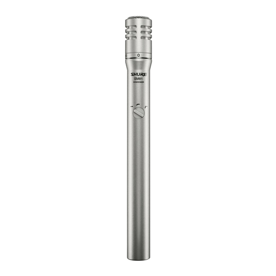
MODEL SM81
UNIDIRECTIONAL CONDENSER MICROPHONE
The Shure Model SM81 is a high-quality, unidirectional
condenser microphone designed for the most demanding pro-
fessional applications in studio recording, broadcasting, and
sound reinforcement. It is especially suitable for applications re-
quiring extremely wide frequency response, low noise and dis-
tortion characteristics, very low RF susceptibility, and reliable
Operation over a wide range of temperature and humidity
extremes. The case is constructed of steel for ruggedness, with
a stainless steel screen, and finished in durable vinyl paint.
The microphone is furnished with a swivel adapter, atten-
uator lock, windscreen, and carrying/storage case. It is sup-
plied without cable. Available accessories are a highly efficient
pop-filter grille (Model A81G), a heavy-duty windscreen (Model
A81WS), a compact, lightweight microphone stand (Model
S15) capable of extension to 4.3 m (14 ft), a versatile stereo mi-
crophone adapter (Model A27M), and a dual-channel phantom
power supply (Model PS1A). An alternative omnidirectional
cartridge (Model R104A) is also available.
Model SM81 Features:
Wide-range, frequency response for exceptionally accu-
rate recording and sound reinforcement applications
Low noise and high output clipping level characteristics
Low distortion characteristics over the entire audio spec-
trum for a wide range of load impedances
Cardioid polar pattern, uniform with frequency and sym-
metrical about axis, to provide maximum rejection and
minimum coloration of off-axis sounds
Very low RF susceptibility
Selectable low-frequency response: flat, 6 or 18 dB/octave
rolloff
10 dB attenuator accessible without disassembly; lockable
in either position
Wide-range phantom powering includes DIN 45 596 volt-
ages of 12 and 48 Vdc
Rugged construction for outstanding reliability
Field-usable over wide range of temperature and humidity
conditions
1996, Shure Brothers Inc.
27A2916 (PA)
Shure Brothers Incorporated
222 Hartrey Avenue
Evanston IL 60202-3696 U.S.A.
Model SM81 User Guide
SPECIFICATIONS
Type
Cardioid
Frequency Response
20 to 20,000 Hz (see Figure 1)
TYPICAL FREQUENCY RESPONSE
Polar Pattern
Cardioid (unidirectional) response—uniform with frequen-
cy, symmetrical about axis (see Figure 2)
TYPICAL POLAR PATTERNS
Output Impedance
Rated at 150 ohms (85 Ω actual)
Recommended minimum load impedance: 800 Ω (May
be used with loads as low as 150 Ω with reduced clip-
ping level)
Output Level (at 1,000 Hz)
Open Circuit Voltage
. . . . . . . . . . . . . . . . .
Equivalent Power Level
Clipping Level (at 1,000 Hz)
800 Ω Load
. . . . . . . . . . . . . . . . . . . . . . . . . .
150 Ω Load
. . . .
. . . . . . . . . . . . . . . . . . . .
FIGURE 1
FIGURE 2
–65 dB (0.56 mV)
(0 dB = 1 volt per µbar)
. . . . . . . . . . . . . . . . . . . . . .
(0 dB = 1 milliwatt per 10 µbars)
–4 dBV (0.63 V)
–15 dBV (0.18 V)
Printed in U.S.A.
–40.5 dB
Advertisement
Table of Contents

Subscribe to Our Youtube Channel
Related Manuals for Shure SM81


Summary of Contents for Shure SM81
- Page 1 20 to 20,000 Hz (see Figure 1) MODEL SM81 UNIDIRECTIONAL CONDENSER MICROPHONE The Shure Model SM81 is a high-quality, unidirectional condenser microphone designed for the most demanding pro- fessional applications in studio recording, broadcasting, and sound reinforcement. It is especially suitable for applications re-...
- Page 2 (–20 to 165 F) Note that a PS1A Power Supply can power two SM81’s on each input; other power supplies should be checked to see if they can Relative Humidity 0–95% .
- Page 3 If the power supply is unregulated, the power supply volt- INPUT FROM age may drop when the SM81 is connected to it, due to the add- MICROPHONE ed load. To account for this load, the value of R may be deter- mined as follows.
- Page 4 “0” or “10” position as desired. Insert the actuator Slip the A81G over the SM81 until the inside of the A81G ring lock (small clear piece of plastic) in the area behind the ac- touches the top of the microphone.
- Page 5 Remove the low-frequency response switch knob by plac- ing a small screwdriver or tweezers into the slot under the A block diagram of the SM81 is shown in Figure 11. The ca- ridge of the knob and lifting outward. pacitor cartridge is followed by a switch-controlled capacitive attenuator stage which provides for 10 dB attenuation at the Remove the small Phillips screw near the plug.
Need help?
Do you have a question about the SM81 and is the answer not in the manual?
Questions and answers