Table of Contents
Advertisement
D-E200/E201/E206CK/E251
SERVICE MANUAL
Ver 1.0 2000. 02
CD player
System
Compact disc digital audio system
Laser diode properties
Material: GaAlAs
Wavelength: λ = 780 nm
Emission duration: Continuous
Laser output: Less than 44.6 µW (This output
is the value measured at a distance of 200 mm
from the objective lens surface on the optical
pick-up block with 7 mm aperture.)
Error correction
Sony Super Strategy Cross Interleave Reed
Solomon Code
D-A conversion
1-bit quartz time-axis control
Frequency response
20 - 20,000 Hz +1/–3 dB
(measured by EIAJ CP-307)
Output (at 4.5 V input level)
Headphones (stereo minijack)
Approx. 15 mW + Approx. 15 mW
at 16 ohms
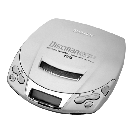
(Photo: D-E201 (Silver))
Model Name Using Similar Mechanism
CD Mechanism Type
Optical Pick-up Name
SPECIFICATIONS
General
Power requirements
For the area code of the model you purchased,
check the upper left side of the bar code on the
package.
• Two LR6 (size AA) batteries: 3 V DC
• AC power adaptor (DC IN 4.5 V jack):
US, CND model: 120 V, 60 Hz
• Sony CPM-300P mount plate for use on car
battery: 4.5 V DC
Battery life (approx. hours) (EIAJ*)
Battery life varies depending on how the player is
used.
ESP OFF
ESP ON
Two alkaline
15
batteries LR6
* Measured value by the standard of EIAJ
(Electronic Industries Association of Japan).
(When the unit is used on a flat and stable place.)
– 1 –
Canadian Model
Dimensions (w/h/d) (without projecting
parts and controls)
Approx. 131 × 28 × 148 mm
× 1
(5
1/4
1/9
Mass
Approx. 220 g (7.8 oz.)
Operating temperature
5°C - 35°C (41°F - 95°C)
Supplied accessories
For the area code of the model you purchased,
check the upper left side of the bar code on the
package.
D-E200
Headphones/earphones (1)
D-E201
14
AC power adaptor (1)
Headphones/earphones (1)
D-E251
AC power adaptor (1)
Headphones/earphones (1)
– Continued on next page –
PORTABLE CD PLAYER
US Model
D-E200/E206CK/E251
D-E201/E206CK
D-190/191
CDM-2811AAC
DAX-11A
× 5
in.)
4/5
Advertisement
Table of Contents

Related Manuals for Sony D-E200


Summary of Contents for Sony D-E200
- Page 1 5°C - 35°C (41°F - 95°C) Supplied accessories is the value measured at a distance of 200 mm • Sony CPM-300P mount plate for use on car from the objective lens surface on the optical battery: 4.5 V DC For the area code of the model you purchased, Battery life (approx.
-
Page 2: Table Of Contents
3-3. MD Assy ................6 function in its intended manner, during the warranty period, the adaptor should be returned to your nearest Sony Service Center or Sony 4. ELECTRICAL ADJUSTMENTS Authorized Repair Center for replacement, or 4-1. Focus Bias Check ..............7 after warranty period, it should be discarded. -
Page 3: Service Note
1. Scatterd light of laser beams is seen. 2. Check for vertical movements (five) of the objective lens (with movement of the PU on the inner circumference). – MAIN BOARD – (SIDE A) D-E251 D-E200/E201/E206CK TAP802 – MAIN BOARD – (SIDE B) S801 (OPEN) S801 –... -
Page 4: General
SECTION 2 GENERAL This section is extracted from instruction manual. – 4 –... - Page 5 – 5 –...
-
Page 6: Disassembly
SECTION 3 DISASSEMBLY Note : Follow the disassembly procedure in the numerical order given. 3-1. CABINET (LOWER) SUB ASSY Note : When installing, fit the knobs (H-B) and switches. 4 claw (Open the battery case Lid.) 3 claw 1 screws (B2x10) (G), tapping 2 screws (B2x10) (G), tapping 7 cabinet (lower) sub assy 5 claw... -
Page 7: Electrical Adjustments
SECTION 4 SECTION 5 ELECTRICAL ADJUSTMENTS DIAGRAMS CD section adjustments are done automatically in this set. 5-1. IC PIN DESCRIPTION Pin No. Pin Name Pin Description In case of operation check, confirm that focus bias. • IC801 TMP88CM22F (SYSTEM CONTROLLER) SEG1 —... -
Page 8: Block Diagram -Cd Section
D-E200/E201/E206CK/E251 5-2. BLOCK DIAGRAM — CD SECTION — DIGITAL SIGNAL PROCESSOR, DIGITAL SERVO PROCESSOR, D-E200/E201/E206CK D-RAM CONTROLLER RF AMP IC601 D-RAM DETECTOR Q501-504 IC603 WDCK (GRSCOR) DIGITAL DOUT D-E251 WFCK D-RAM RFDC IC602 RFAC XTAO XTAI D1-D4 VCC +2.5V RFAC... -
Page 9: Block Diagram -Power Supply Section
D-E200/E201/E206CK/E251 5-3. BLOCK DIAGRAM — POWER SUPPLY SECTION — POWER CONTROL IC401 (1/2) DTC2D SYNC SYNC (Page 11) DTC1D SDTO DATA (Page 11) BATM1 CHARGING BATTERY BATM2 (Page 11) CLOCK VOLTAGE DETECTOR CHG SW CIRCUIT CHGMNT PICK-UP LINEAR POWER CONTROL... -
Page 10: Printed Wiring Boards -Main Section
D-E200/E201/E206CK/E251 5-4. PRINTED WIRING BOARDS — MAIN SECTION — MAIN BOARD (SIDE A) R411 C431 OPTICAL PICK-UP BLOCK DAX-11A M501 SLED MOTOR VDR101 M502 SPINDLE MOTOR Note on Printed Wiring Boards: VDR201 • Y : parts extracted from the conductor side. - Page 11 D-E200/E201/E206CK/E251 J401 • Waveforms (Play mode) DC IN 4.5V MAIN BOARD (SIDE B) 0.46 - 0.66Vp-p S801 0.5µsec/div (OPEN) TP652 (RF) 50mVp-p 20µsec/div TP620 (FOK) 2Vp-p 2µsec/div (MDP) IC601 2Vp-p 0.5µsec/div TP613 (SCK) 2Vp-p 5µsec/div R457 TP642 (LRCK) DRY BATTERY SIZE "AA"...
- Page 12 D-E200/E201/E206CK/E251 5-5. SCHEMATIC DIAGRAM — MAIN SECTION (1/2) — • Refer to page 18 for Waveforms. • Refer to page 23 for IC Block Diagrams. (Page 21) – 19 – – 20 –...
-
Page 13: Schematic Diagram -Main Section (1/2)
D-E200/E201/E206CK/E251 5-6. SCHEMATIC DIAGRAM — MAIN SECTION (2/2) — • Refer to page 24 for IC Block Diagrams. (Page 20) – 21 – – 22 –... -
Page 14: Ic Block Diagrams
5-7. IC Block Diagrams IC601 CXD3027R IC302 TA2120FN BIAS BEEP BIAS IN B IN A 120 119 118 117 116 115 114 113 112 111 110 109 108 107 106 105 104 103 102 101 100 99 98 97 96 95 94 93 92 91 BIAS BEEP OUT B... -
Page 15: Exploded Views
SECTION 6 EXPLODED VIEWS NOTE: • The mechanical parts with no reference • Accessories and packing materials are The components identified by mark 0 or dotted line with mark number in the exploded views are not supplied. given in the last of this parts list. 0 are critical for safety. -
Page 16: Cabinet (Lower) Section
6-2. CABINET (LOWER) SECTION CDM-2811AAC LCD801 Ref. No. Part No. Description Remark Ref. No. Part No. Description Remark 4-214-676-01 INSULATOR X-3378-734-1 CABINET (LOWER) SUB ASSY A-3323-506-A MAIN BOARD, COMPLETE (E200/E201/E206CK) 4-966-278-01 FOOT, RUBBER A-3323-518-A MAIN BOARD, COMPLETE (E251) 4-214-867-11 LID, BATTERY CASE 4-214-872-01 HOLDER (LCD) 4-218-592-01 CUSHION 4-214-642-01 TERMINAL BOARD (RELAY), BATTERY... -
Page 17: Cd Mechanism Deck Section (Cdm-2811Aac)
6-3. CD MECHANISM DECK SECTION (CDM-2811AAC) M502 M501 The components identified by Les composants identifiés par une mark 0 or dotted line with mark marque 0 sont critiques pour la 0 are critical for safety. sécurité. Replace only with part number Ne les remplacer que par une piéce specified. -
Page 18: Electrical Parts List
SECTION 7 MAIN ELECTRICAL PARTS LIST NOTE: • Due to standardization, replacements in • Items marked “*” are not stocked since The components identified by mark 0 or dotted line with mark the parts list may be different from the they are seldom required for routine service. - Page 19 MAIN Ref. No. Part No. Description Remark Ref. No. Part No. Description Remark C626 1-104-847-11 TANTAL. CHIP 22uF IC602 8-759-594-56 IC MSM51X17400D-10TFSR1 (E251) C627 1-164-156-11 CERAMIC CHIP 0.1uF IC603 8-759-670-17 IC MSM51V4400D-70SJ7FS1 C628 1-162-962-11 CERAMIC CHIP 470PF (E200/E201/E206CK) C629 1-164-156-11 CERAMIC CHIP 0.1uF IC801 8-759-671-03 IC TMP88CH22F-1A75...
- Page 20 MAIN Ref. No. Part No. Description Remark Ref. No. Part No. Description Remark R301 1-216-845-11 METAL CHIP 100K 1/16W R505 1-216-831-11 METAL CHIP 6.8K 1/16W R353 1-216-308-00 METAL CHIP 1/10W R506 1-216-821-11 METAL CHIP 1/16W R401 1-216-861-11 METAL CHIP 2.2M 1/16W R507 1-216-821-11 METAL CHIP...
- Page 21 MAIN Ref. No. Part No. Description Remark Ref. No. Part No. Description Remark R811 1-218-863-11 METAL CHIP 4.7K 0.5% 1/16W MISCELLANEOUS R812 1-218-855-11 METAL CHIP 2.2K 0.5% 1/16W *************** R813 1-216-837-11 METAL CHIP 1/16W 0 101 (E251) X-4951-546-1 DAX-11A RP ASSY R813 1-216-839-11 METAL CHIP 1/16W...
- Page 22 D-E200/E201/E206CK/E251 Sony Corporation 2000B0419-1 9-927-666-11 Personal Audio Division Company Printed in Japan C2000.2 – 32 – Published by General Engineering Dept.
Need help?
Do you have a question about the D-E200 and is the answer not in the manual?
Questions and answers
Unit came in with a slightly corroded battery contact. After cleaning, it spins the CD for a few seconds and says "no Cd". Lens has been cleaned. Lookling for more ideas.