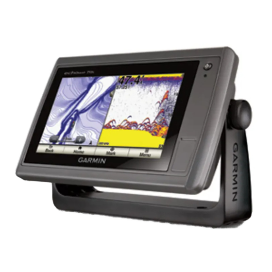
Garmin echoMAP 70 Series Installation Instructions
Hide thumbs
Also See for echoMAP 70 Series:
- Installation instructions (4 pages) ,
- Owner's manual (50 pages) ,
- Installation instructions manual (34 pages)
Advertisement
Quick Links
echoMAP
™
70/90 Series Installation
Instructions
To obtain the best performance and to avoid damage to your
boat, install the device according to these instructions.
Read all installation instructions before proceeding with the
installation. If you experience difficulty during the installation,
contact Garmin
Product Support.
®
Important Safety Information
See the Important Safety and Product Information guide in the
product box for product warnings and other important
information.
When connecting the power cable, do not remove the in-line
fuse holder. To prevent the possibility of injury or product
damage caused by fire or overheating, the appropriate fuse
must be in place as indicated in the product specifications. In
addition, connecting the power cable without the appropriate
fuse in place voids the product warranty.
Always wear safety goggles, ear protection, and a dust mask
when drilling, cutting, or sanding.
When drilling or cutting, always check what is on the opposite
side of the surface.
To obtain the best performance and to avoid damage to your
boat, install the device according to these instructions.
Read all installation instructions before proceeding with the
installation. If you experience difficulty during the installation,
contact Garmin Product Support.
Registering Your Device
Help us better support you by completing our online registration
today.
• Go to http://my.garmin.com.
• Keep the original sales receipt, or a photocopy, in a safe
place.
Contacting Garmin Product Support
• Go to
www.garmin.com/support
information.
• In the USA, call 913-397-8200 or 1-800-800-1020.
• In the UK, call 0808 238 0000.
• In Europe, call +44 (0) 870 850 1241.
Tools Needed
• Drill and drill bits
• #2 Phillips screwdriver
• Jigsaw or rotary tool
• File and sandpaper
• Marine sealant (optional)
Mounting Considerations
The device can be mounted using the included bracket, or it can
be mounted flush with the dashboard using a flush-mount kit
(may be sold separately).
December 2014
WARNING
CAUTION
NOTICE
for in-country support
Before permanently installing any part of your device, you
should plan the installation by determining the location of the
various components.
• The mounting location must provide a clear view of the
screen and access to the keys on the device.
• The mounting location must be sturdy enough to support the
device and the mount.
• The cables must be long enough to connect the components
to each other and to power.
• The cables can be routed under the bail mount or behind the
device.
• To avoid interference with a magnetic compass, the device
should not be installed closer to a compass than the
compass-safe distance value listed in the product
specifications.
Bail Mounting the Device
If you are mounting the bracket on fiberglass with screws, it is
recommended to use a countersink bit to drill a clearance
counterbore through only the top gel-coat layer. This will help to
avoid any cracking in the gel-coat layer when the screws are
tightened.
Stainless-steel screws may bind when screwed into fiberglass
and overtightened. Garmin recommends applying an anti-seize
lubricant to the screws before installing them.
1
Select the mounting hardware appropriate for your mounting
surface and for the bail-mount bracket.
2
Using the bail-mount bracket
holes through the screw holes
3
Using a drill bit appropriate for the mounting hardware, drill
the four pilot holes.
4
Using the selected mounting hardware, secure the bail-mount
bracket to the mounting surface.
5
Place the device into the cradle
6
Install the bail-mount knobs
7
Place the cradle in the bail-mount bracket and tighten the
bail-mount knobs.
Flush Mounting the Device
Be careful when cutting the hole to flush mount the device.
There is only a small amount of clearance between the case and
the mounting holes, and cutting the hole too large could
compromise the stability of the device after it is mounted.
Using a metal pry tool such as a screwdriver can damage the
trim caps and the device. Use a plastic pry tool when possible.
Printed in Taiwan
NOTICE
as a template, mark the pilot
.
.
on the sides of the device.
NOTICE
190-01835-02_0B
Advertisement

Related Manuals for Garmin echoMAP 70 Series


Summary of Contents for Garmin echoMAP 70 Series
-
Page 1: Important Safety Information
Stainless-steel screws may bind when screwed into fiberglass and overtightened. Garmin recommends applying an anti-seize CAUTION lubricant to the screws before installing them. Always wear safety goggles, ear protection, and a dust mask when drilling, cutting, or sanding. - Page 2 The pieces of the rubber gasket have adhesive on the back. 12 Vdc power source Make sure you remove the protective liner before installing Wiring harness them on the device. NMEA 0183-compliant device Item Garmin Wire Garmin Wire NMEA 0183 Device Wire Function Color Function...
-
Page 3: Updating The Device Software
Go to www.garmin.com or contact your local Garmin dealer to determine the appropriate type of transducer for your needs. Follow the instructions provided with your transducer to correctly install it on your boat. -
Page 4: Nmea 0183 Information
Wind speed and angle Garmin ® and the Garmin logo are trademarks of Garmin Ltd. or its subsidiaries, registered in the USA and other countries. echoMAP ™ is a trademark of Garmin Ltd. or its subsidiaries. These trademarks may not be used without the express permission of Garmin.
Need help?
Do you have a question about the echoMAP 70 Series and is the answer not in the manual?
Questions and answers