Table of Contents
Advertisement
Available languages
Available languages
Advertisement
Chapters
Table of Contents

Related Manuals for Truma BC 616 IU


Summary of Contents for Truma BC 616 IU
- Page 1 Battery Charger BC 616 IU Gebrauchsanweisung Seite 2 Einbauanweisung Operating instructions Page 16 Installation instructions Mode d‘emploi Page 30 Instructions de montage Istruzioni per l‘uso Pagina 44 Istruzioni di montaggio Komfort für Unterwegs...
-
Page 2: Table Of Contents
Sicherheitshinweise ............ 3 Handhabung der Käfigzugfederklemmen .... 12 Anschluss ................ 12 Verwendungszweck .............. 4 Bestimmungswidriger Gebrauch ........ 4 Anschlussplan .............. 14 Beschreibung .............. 4 Inbetriebnahme .............. 14 Anschlüsse ................ 5 Netzbetrieb auf Fähren ............ 15 Ladevorgang ............... 5 Generatorbetrieb .............. 15 Versorgungsbatterie (Batterie II) ........... 5 Starterbatterie (Batterie I) – Parallelschaltung ...... 6 Wartung ................ 6 Entsorgung ................ 6 Technische Daten ............... 7 Abmessungen / Gewicht ........... 8 Ladekennlinie .............. 8 Fehlersuchanleitung ............ 8 Zubehör ................ 9 Truma Hersteller Garantieerklärung ...... 10... -
Page 3: Gebrauchsanweisung
Glossar Aufstellen Achten Sie darauf, dass die Geräte sicher aufgestellt werden AGM-Batterie Blei-Säure-Batterie, bei der der und nicht herabfallen oder umstürzen können. Legen Sie Elektrolyt in einem Mikroglasvlies Leitungen stets so, dass keine Stolpergefahr entsteht. Setzen (absorbed glass mat) festgelegt ist. Sie Elektrogeräte nicht dem Regen aus. Betreiben Sie Elektro- Batterie OPTIMA® YT S entspricht einer AGM-Batterie. geräte nicht in feuchter oder nasser Umgebung. Betreiben Sie Elektrogeräte nicht in der Nähe von brennbaren Flüssigkeiten oder Gasen. Stellen Sie Ihre elektrischen Geräte so auf, dass Verwendete Symbole Kinder keinen Zugriff darauf haben. Schutz vor elektrischem Schlag Symbol weist auf mögliche Gefahren hin. Betreiben Sie nur Geräte deren Gehäuse und Leitungen un- beschädigt sind. Achten Sie auf sichere Verlegung der Kabel. Ziehen Sie nicht an den Kabeln. Hinweis mit Informationen und Tipps. Den elektrischen Anschluss der Geräte über einen Fehlerstromschutzschalter 30 mA Nennfehlerstrom a bsichern und nur so betreiben. EVU-Vorschriften beachten. Gebrauch Benutzen Sie keine elektrischen Geräte entgegen dem, vom Hersteller angegebenen Verwendungszweck. Instandsetzung Nehmen Sie keine Instandsetzungsarbeiten oder Verände- rungen am Gerät vor. Wenden Sie sich an Ihren Händler oder an den Truma Service (siehe Serviceheft oder www.truma.com). Zubehör Benutzen Sie nur Zubehörteile und Zusatzgeräte die vom Her- steller geliefert oder empfohlen werden. -
Page 4: Verwendungszweck
Einbau in Caravans, Motorcaravans und Boote bestimmt. wird die Lebensdauer der Batterie wesentlich verlängert. Nach Herstellen des Batterieanschlusses und des Netzanschlusses ist der Ladeautomat in Betrieb. Bestimmungswidriger Gebrauch Der Ladeautomat ist für Dauerbetrieb und Parallelbetrieb Nicht für 6 V Batterien, oder nichtaufladbare Batterien konzipiert. Verbraucher können ständig angeschlossen blei- verwenden! ben, dazugeschaltet oder weggeschaltet werden. Es werden gleichzeitig die Verbraucher versorgt und die Batterie geladen. Der Ladeautomat darf nicht zum Laden von 6 V Bleiakkumu- Der Verbraucherstrom soll hierbei kleiner als der max. Lade- latoren verwendet werden. Werden Batterien mit einer Nenn- strom sein, da sonst keine Ladung der Batterie erfolgt. spannung von 6 V mit dem Ladeautomat geladen, so setzt die Gasung sofort ein. Es entsteht explosives Knallgas. Unter Verwendung eines Ladekontroll-Panels, z. B. dem Truma Panel BC (616) wird die Betriebsbereitschaft angezeigt Der Ladeautomat darf nicht zum Laden von nichtaufladbaren (Netzanschluss und Batterieanschluss vorhanden). Auch Batterien und / oder Nickel-Cadmium-Batterien verwendet eventuelle Störungen des Ladeautomaten werden auf dem werden. Truma Panel BC (616) durch ein Blinken der LED für Batterie II angezeigt. Beim Laden dieser Batteriearten, mit dem Ladeautomat, kann die Hülle explosionsartig aufplatzen. Wird der Ladeautomat zusammen mit einem Temperaturfühler für die Versorgungsbatterie (Batterie II) betrieben, so regelt der Ladeautomat die Ladespannung automatisch in Abhängigkeit der Batterietemperatur. Hierdurch wird eine besonders effek- tive und schonende Ladung der Batterie erreicht. Ohne Ver- wendung eines Temperaturfühlers regelt der Ladeautomat den Ladevorgang wie bei einer Batterietemperatur von 20 °C. Das Gerät ist für den Betrieb in einer Umgebungstemperatur bis 35 °C ausgelegt. Steigt die Geräteinnentemperatur durch mangelnde Luftzirkulation oder zu hohe Umgebungstempera-... -
Page 5: Anschlüsse
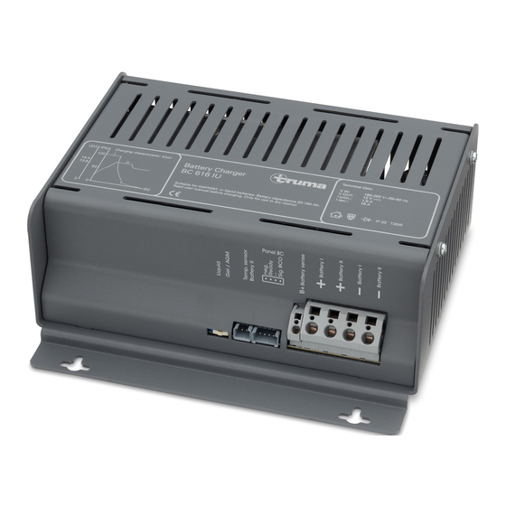
Anschlüsse spannung ständig über die B+ Messleitung überwacht. Der Ladevorgang erfolgt gemäß der Ladekennlinie unter gerings- ter Verlustleistung. (Ladekennlinie siehe Bild 2). Panel BC Hauptladephase (alle Spannungswerte bezogen auf 20 °C Batterietemperatur) Ladung mit maximalem konstanten Ladestrom bis annähernd 14,4 V Batteriespannung erreicht sind. Sinkt in diesem Bereich der Hauptladephase der Ladestrom bedingt durch den Batte- rieinnenwiderstand und Leitungswiderstände unter 90 % des Nennstromes ab, wird die Nachladephase gestartet. Nachladephase (alle Spannungswerte bezogen auf 20 °C Batterietemperatur) Die Ladespannung wird über eine Zeitdauer von zehn Stunden bei Gelbatterien / AGM bzw. vier Stunden bei Flüssigelektrolyt- Bild 1: Anschlüsse batterien konstant auf 14,4 V gehalten. Nach Ablauf dieser Zeit erfolgt eine Umschaltung in die Erhaltungsladephase. Steigt 1 Kaltgerätesteckeranschluss 230 V ~ während dieser Zeit der Strom auf über 90 % des Nennstromes 2 Umschalter Gel- bzw. AGM (OPTIMA® YT S) / und sinkt dabei die Batteriespannung für einen Zeitraum von Flüssigelektrolytbatterie mehr als 15 Minuten bei Flüssigelektrolytbatterien und mehr 3 Anschluss für Temperaturfühler als zwei Stunden bei Gel- und AGM-Batterien unter 13,2 V, so 4 Anschluss für Ladekontroll-Panel erfolgt eine Umschaltung zurück in die Hauptladephase. 5 Eingang B+ Messleitung von Batterie II 6 Ausgang + Ladeleitung Batterie I Erhaltungsladephase 7 Ausgang + Ladeleitung Batterie II (alle Spannungswerte bezogen auf 20 °C Batterietemperatur) 8 Ausgang - Ladeleitung Batterie I Die Ladespannung ist auf 13,8 V eingestellt. Der Ladestrom... -
Page 6: Starterbatterie (Batterie I) - Parallelschaltung
Wartung Starterbatterie (Batterie I) – Parallelschaltung Fahrbetrieb Vor allen Wartungsarbeiten am Gerät unbedingt die Im Fahrbetrieb wird die Starterbatterie (Batterie I) von der Stromzufuhr unterbrechen. Lichtmaschine des Kraftfahrzeuges geladen. Solange die Lichtmaschine läuft und die Spannung an der Starterbatterie Reinigen Sie das Gerät und die Lüftungsschlitze mit einem über 13,7 V ansteigt, werden die Versorgungsbatterie und die t rockenen, fusselfreien Tuch. Starterbatterie parallel geschaltet. Die Versorgungsbatterie wird von der Lichtmaschine mitgeladen. Fällt die Spannung Entsorgung an der Starterbatterie unter 13,2 V, wird die Parallelschaltung wieder aufgehoben. Das Gerät ist gemäß den administrativen Bestimmungen des Netzbetrieb jeweiligen Verwendungslandes zu entsorgen. Nationale Vor- (alle Spannungswerte bezogen auf 20 °C Batterietemperatur) schriften und Gesetze (in Deutschland ist dies z. B. die Altfahr- Bei 230 V Netzanschluss wird die Versorgungsbatterie vorran- zeug-Verordnung) müssen beachtet werden. gig geladen. Erreicht die Versorgungsbatterie die Spannung von 14,1 V, erfolgt die Parallelschaltung mit der Starterbatterie. Steigt der Ladestrom bedingt durch Verbraucher auf seinen Nennwert und sinkt die Batteriespannung unter einen Wert von 13,2 V, so wird die Parallelschaltung automatisch aufge- hoben. Die Starterbatterie bleibt somit immer startfähig. Solarbetrieb Bei Anschluss externer Solarzellen wird die Starterbatterie mitgeladen, wenn die Versorgungsbatterie eine Spannung von 14,1 V erreicht hat. Fällt die Spannung der Versorgungs- batterie unter 13,2 V ab, so wird die Parallelschaltung wieder aufgehoben. -
Page 7: Technische Daten
Technische Daten Anwendung Parallelbetrieb, allgemeiner Ladebetrieb. Spannungsversorgung Wechselspannung 230 V / 50 Hz, einphasig Temperatur Bereich ca. 180 V – 250 V / 50 – 60 Hz Umgebungstemperatur von -25 °C bis +35 °C. Bei Betrieb kann sich das Gehäuse auf ca. 75 °C erwärmen. Ausgangsstrom (Ladestrom Batterie II) Kühlung Ladestrom max. 16 A, arithmetischer Mittelwert, elektronisch geregelt entsprechend der Ladekennlinie IUoU Durch Konvektion. Ausgangsstrom (Ladestrom Batterie I) Ausführung Ab 14,1 V Batteriespannung der Batterie II erfolgt die Parallel- Gemäß den Bestimmungen des VDE und des schaltung mit Batterie I. Ausgleichsstrom je nach Ladezustand der Gerätesicherheitsgesetzes. Batterie I (Starterbatterie). Fällt die Spannung der Batterie II unter Verwendung 13,2 V ab, wird die Parallelschaltung automatisch aufgehoben. Zum Laden von Batterien mit 12 V Nennspannung und einer Ausgangsspannung Kapazität von 50 – 160 Ah. Gleichspannung 12 V Ladevorgang Automatisch Schaltautomatik (Hauptladevorgang) AUS bei Batteriespannung 14,4 V, Ladestrom < 14,5 A. Schaltautomatik (Nachladephase) 10 Stunden konstant 14,4 V bei Gel-Batterien / AGM 4 Stunden konstant 14,4 V bei Flüssigelektrolytbatterien Schaltautomatik (Erhaltungsladung) Erhaltungsladung konstant 13,8 V Temperaturabhängige Regelung (optional) Die Werte der Schaltautomatik beziehen sich auf eine Batte- rietemperatur von 20 °C. Unter Verwendung des Temperatur- fühlers an der Batterie II variieren diese Werte in Abhängigkeit von der Batterietemperatur. -
Page 8: Abmessungen / Gewicht
Sie den Kaltgerätestecker am Gewicht Gerät aus und wieder ein. 1,3 kg Prüfen Sie die Sicherungen und den Netzanschluss. Die Spannung der Batterie II Starten Sie den Motor und Ladekennlinie ist unter 1,5 Volt gesunken. lassen Sie ihn ca. 30 Sekun- den laufen. Die Batteriespan- HL = Hauptladephase nung steigt über 1,5 Volt. NL = Nachladephase Der Ladevorgang beginnt EL = Erhaltungsladung selbständig. U[V] I[%] Der maximale Ladestrom Das Gerät wird zu warm, wird nicht erreicht. sorgen Sie für bessere B elüftung des Gerätes. 14,4 Sollten diese Maßnahmen nicht zur Störungsbehebung 13,8 führen, wenden Sie sich bitte an das Truma Service- zentrum. t[h] Bild 2: Ladekennlinie (prinzipieller Verlauf) Technische Änderungen vorbehalten. -
Page 9: Zubehör
Ladekontroll-Panel Panel BC (616) zur Anzeige von Ladetätigkeit und Parallel- schaltung von Starter- und Versorgungsbatterie in Verbindung Quickpower Polklemmen mit dem Ladeautomaten BC 616 IU. Zum schnellen Verbinden und Lösen von Batteriean- Panel BC (616) mit schlüssen von Hand. Passend 4-poligem Steuerkabel 5 m und für alle Anschlüsse nach DIN... -
Page 10: Truma Hersteller Garantieerklärung
1. Garantiefall Mangels – insbesondere Transport-, Wege-, Arbeits- und Materialkosten – trägt der Hersteller, soweit der Kundendienst Der Hersteller gewährt Garantie für Mängel des Gerätes, die innerhalb von Deutschland eingesetzt wird. Kundendienstein- auf Material- oder Fertigungsfehler zurückzuführen sind. Da- sätze in anderen Ländern sind nicht von der Garantie gedeckt. neben bestehen die gesetzlichen Gewährleistungsansprüche gegen den Verkäufer fort. Zusätzliche Kosten aufgrund erschwerter Aus- und Einbaubedin- gungen des Gerätes (z. B. Demontage von Möbel- oder Karosse- Der Garantieanspruch besteht nicht: rieteilen) können nicht als Garantieleistung anerkannt werden. – für Verschleißteile und bei natürlicher Abnutzung, 3. Geltendmachung des Garantiefalles – infolge Verwendung von anderen als Truma Originalteilen in den Geräten, Die Anschrift des Herstellers lautet: Truma Gerätetechnik GmbH & Co. KG, – infolge Nichteinhaltung der Truma Einbau- und Wernher-von-Braun-Straße 12, Gebrauchsanweisungen, 85640 Putzbrunn. – infolge unsachgemäßer Behandlung, In Deutschland ist bei Störungen grundsätzlich das Truma S ervicezentrum zu benachrichtigen; in anderen Ländern – infolge unsachgemäßer Transportverpackung. s tehen die jeweiligen Servicepartner zur Verfügung (siehe Truma Serviceheft oder www.truma.com). Beanstandungen sind näher zu bezeichnen. Ferner ist die ordnungsgemäß aus- 2. Umfang der Garantie gefüllte Garantie-Urkunde vorzulegen oder die Fabriknummer des Gerätes sowie das Kaufdatum anzugeben. -
Page 11: Einbauanweisung
Aufstellen Einbauanweisung Den im Umkarton befindlichen Beipack (Zubehör) entnehmen und auf Vollständigkeit prüfen: Sicherheitshinweise 1 Gebrauchs- und Einbauanweisung In diesem Gerät sind Bauteile eingebaut, die einen 1 Anschlusskabel 230 V, 1 m F unken oder Lichtbogen erzeugen können! 1 Sicherung 30 A 1 Sicherungshalter Der Anschluss des Versorgungsnetzes an das Gerät muss in 4 Befestigungsschrauben Übereinstimmung mit den jeweils geltenden nationalen Instal- 4 Unterlegscheiben lationsvorschriften vorgenommen werden. 4 Kabelschuhe 2 Klappferrite Die Montage und der Anschluss von elektrischen Geräten muss grundsätzlich durch geeignetes Fachpersonal erfolgen! Das Gerät ist vor Feuchtigkeit und Nässe geschützt aufzustellen. Der Aufstellungsort muss sauber, trocken und gut belüftet sein. Stellen Sie sicher, dass die Stromzufuhr getrennt ist! Netz- Bei Betrieb kann sich das Gehäuse auf ca. 75 °C erwärmen. Hal- stecker ziehen! ten sie daher einen Mindestabstand von 100 mm ein und achten Sie darauf, dass die Lüftungsschlitze nicht verdeckt werden. Benutzen Sie zum Anschluss des Gerätes nur die mitgeliefer- ten Teile sowie die vorgeschriebenen Leitungsquerschnitte Der für das Gerät bereitgestellte Raum darf nachfolgende Ab- und Sicherungen! messungen nicht unterschreiten, da der Mindestabstand von rundum 100 mm gewährleistet sein muss. Benutzen Sie nur geeignetes und einwandfreies Werkzeug. Länge: 420 mm / Breite: 410 mm / Höhe: 190 mm Schließen Sie das Gerät nur gemäß des mitgelieferten An- Der Einbauraum für das Gerät muss oben und seitlich mit Lüf- schlussplanes an! tungsöffnungen versehen sein, die eine Gesamtöffnung von 100 cm² ergeben. -
Page 12: Handhabung Der Käfigzugfederklemmen
Anschluss Achten sie darauf, dass die Lüftungsschlitze frei bleiben! Der Mindestabstand muss rundum 100 mm betragen! Un- zureichende Belüftung kann zur Überhitzung des Gerätes führen! Vor dem Anschließen oder Trennen von Leitungen sind die Versorgungsleitungen von Batterie und Netz Das Gerät ist für den Betrieb in einer Umgebungstemperatur zu trennen! Nur vorgeschriebene Leitungsquerschnitte und bis 35 °C ausgelegt. Steigt die Geräteinnentemperatur durch S icherungsstärken verwenden! mangelnde Luftzirkulation oder zu hohe Umgebungstempera- Plus-Ladestromleitung rot tur, so reduziert sich der Ladestrom automatisch stufenweise. Leitungsquerschnitt 6 mm² Minus-Ladestromleitung blau Handhabung der Käfigzugfederklemmen Leitungsquerschnitt 6 mm² B+ Messleitung rot Bereiten Sie die Anschlusskabel vor. Das Kabelende für die Leitungsquerschnitt 0,75 mm² Anschlüsse B+ (kleine Käfigzugfederklemmen) muss auf Anschluss Batterien 8 – 9 mm abisoliert sein. Die Kabelenden für die Batterie- anschlüsse (große Käfigzugfederklemmen) müssen auf Verbinden Sie das Ladegerät gemäß Anschlussplan (Bild 3) 11 – 12 mm abisoliert sein. Aderendhülsen sind nicht mit der Versorgungsbatterie (Batterie II). Achten Sie auf die erforderlich. Leitungsquerschnitte und den richtigen Anschluss der Pole Die Zugfederklemme kann mit Hilfe eines passenden Schlitz- – Die Minus-Ladestromleitung für die Batterie II (blau 6 mm²) schraubendrehers geöffnet werden. an den Minusausgang am Gerät und den Minuspol der Batterie II anschließen. Führen Sie hierzu den Schlitzschraubendreher in die obere, quadratische Öffnung ein und drücken Sie die Zugfederklemme – Die Plus-Ladestromleitung für die Batterie II (rot 6 mm²) an auf. Der Klemmteil der Feder in der unteren, runden Öffnung den Plusausgang für Batterie II am Gerät und den Pluspol schwenkt dabei auf. - Page 13 – Die Minus-Ladestromleitung für die Batterie I (blau 6 mm²) Ladekontroll-Panel an den Minusausgang am Gerät und den Minuspol der Falls Sie ein Ladekontroll-Panel verwenden, stecken Sie dieses Batterie I anschließen. am Anschluss Panel BC (4-polig) am Gerät an. – Die Plus-Ladestromleitung für die Batterie I (rot 6 mm²) an Temperaturfühler den Plusausgang für Batterie I am Gerät und den Pluspol Falls Sie einen Temperaturfühler für die Batterie II verwenden, der Batterie I anschließen. Diese Leitung ist unbedingt, kleben Sie den Temperaturfühler an die Stirnseite der Batte- nahe dem Pluspol der Batterie I, mit der mitgelieferten rie II (Versorgungsbatterie). Hierzu entfernen Sie die Schutz- 30 A Sicherung abzusichern! folie am Klebepunkt des Temperaturfühlers und drücken ihn kräftig auf die gewünschte Position an der Batterie II (siehe Klappferrit Beschreibung Temperaturfühler). Stecken Sie das Kabel des Bringen Sie den Klappferrit nahe am Gerät an, um eine opti- Temperaturfühlers an den Temperaturfühleranschluss des male Entstörung zu erreichen. Legen Sie hierzu die Plus- und G erätes an (2-poliger Anschluss). Minusleitung der 12 V-Anschlüsse in den aufgeklappten Ferrit, Umschalter Batterietyp schließen sie den Klappferrit und drücken Sie ihn zusammen bis die Verriegelung einrastet. Fixieren Sie den Klappferrit Stellen Sie den verwendeten Batterietyp (Flüssigelektrolyt durch je einen Kabelbinder vor und hinter dem Ferrit auf den oder Gel / AGM) Ihrer Batterien am Umschalter ein. Leitungen. Netzanschluss 1 Käfigzugfederklemmen Schließen Sie das Netzkabel an die Netzverteilung Ihres Bootes, 2 Minus-Ladestromleitung Reisemobiles oder Wohnwagens an. Grün / gelbe Leitung an blau Schutzerde!
-
Page 14: Anschlussplan
Anschlussplan Inbetriebnahme Sicherungen unbedingt nahe der Pluspole der Batterien Der Ladeautomat ist in Betrieb sobald die Netzverbindung anbringen! hergestellt ist. Vor dem Unterbrechen oder Schließen von Gleichstromver- Panel BC bindungen, z. B. Ladestromkabel an der Batterie, ist das Gerät netzseitig abzuschalten. Netzstecker ziehen. Batterien mit Zellenschluss dürfen nicht geladen werden. E xplosionsgefahr durch Knallgasentwicklung! Voraussetzungen Die Batterie muss eine Nennspannung von 12 V und eine M indestkapazität von 50 Ah haben. Batterien unter dieser Mindestkapazität werden nur unzureichend geladen. Batterien mit einer zu hohen Kapazität werden zu langsam geladen. Ladevorgang Das Laden der Batterie erfolgt automatisch. Nach zwischen- zeitlichem Netzausfall wird automatisch der Hauptladevorgang neu gestartet. Der Hauptladevorgang wird beendet, wenn die RT 6 mm² Batteriespannung 14,4 V erreicht. Nach Ablauf der Nachla- BL 6 mm² dephase erfolgt die Umschaltung auf Erhaltungsladung von 2 A* konstant 13,8 V. Parallelbetrieb Bei Parallelbetrieb soll der Verbraucherstrom kleiner als der maximale Ladestrom von 16 A sein. Nur so ist sichergestellt, Bild 4: Anschlussplan dass die Batterien aufgeladen werden, obwohl Verbraucher versorgt werden. -
Page 15: Netzbetrieb Auf Fähren
Netzbetrieb auf Fähren Die Netzspannung auf Fähren kann starken Schwankungen unterworfen sein. Verbinden Sie daher das Gerät nicht mit dieser Spannung. Generatorbetrieb Bitte beachten Sie die in der Betriebsanleitung des Herstellers vorgegebene Handhabung. Der Generator muss die 230 V Netzanschlusswerte einhalten. Schließen Sie das Gerät erst dann an den Generator an, wenn dieser stabil läuft und tren- nen Sie das Gerät von diesem, bevor Sie ihn abschalten. Die in der Anlauf- und Abstellphase entstehenden Spannungsspitzen könnten das Gerät schädigen. - Page 16 Automatic Charger BC 616 IU Table of contents Operating instructions Installation instructions Safety instructions ............ 25 Glossary ................ 17 Installation ................. 25 Symbols used .............. 17 Safety instructions ............ 17 Handling of the cage tension spring clamps .... 26 Connection ................ 26 Application purpose ............ 18 Improper use .............. 18 Wiring diagram .............. 28 Description ................ 18 Taking into operation ............ 29 Connections .............. 19 Mains supply mode on ferries .......... 29 Charging process ............. 19 Generator mode .............. 29 Supply battery (battery II) ........... 19 Starter battery (battery I) – parallel switching .... 20 Maintenance .............. 20 Disposal ................ 20 Technical Data .............. 21 Dimensions / weight ............ 21 Charging reference line .
-
Page 17: Operating Instructions
Please be sure to read the instructions for installation when using electrical devices. Please read and follow these and use before attempting to connect and use this i nstructions before using the device. device! Installation Ensure that the devices are positioned safely and cannot fall Glossary down or over. Always position the cables to ensure they do not pose a tripping hazard. Do not expose electrical devices to AGM-battery Lead acid battery, in which the elec- rain. Do not operate electrical devices in damp or wet environ- trolyte is set in an absorbed glass mat. ments. Do not operate electrical devices close to flammable Battery OPTIMA® YT S corresponds to an AGM-battery. liquids or gases. Position the devices so that they are out of the reach of children. Symbols used Protection against an electrical shock Only operate devices whose casings and cables are undam- aged. Ensure the cables are installed safely. Do not pull on the Symbol indicates a possible hazard. cables. Only operate the device if it has been secured with a Comment including information and tips. 30 mA fault-current circuit breaker. Observe the EVU-regulations. Do not use electrical devices for purposes other than those stated by the manufacturer. Repairs Do not repair or modify the device. Please contact your dealer or the Truma Service (see service manual or www.truma.com). Accessories Only use accessories and additional devices that are supplied or recommended by the manufacturer. Application purpose... -
Page 18: Improper Use
Improper use mains supply have been connected, the automatic charger is ready for use. Do not use for 6 V batteries or non-chargeable batteries! The automatic charger is designed for continuous operation and parallel mode. Consumers can be continuously connect- The automatic charger may not be used to charge 6 V lead ac- ed, switched on or disconnected. Consumers are supplied and cumulators. If batteries with a rated voltage of 6 V are charged the battery charged at the same time. The consumer current with the automatic charger, gassing occurs immediately here should be smaller than the maximum charging current as which creates an explosive detonating gas. otherwise the battery will not charge. The automatic charger may not be used to charge non- The operational readiness is shown when a charging con- chargeable batteries and / or nickel-cadmium batteries. trol panel, e.g. the Truma Panel BC (616), is used (mains c onnection and battery connection available). Also, any mal- If the automatic charger is used to charge these batteries, the functions of the automatic charger are shown on the Truma case can burst explosively. Panel BC (616) via the LED for Battery II which flashes. If the automatic charger is operated in conjunction with a temperature sensor for the supply battery (Battery II), the a utomatic charger regulates the charging current automati- cally depending on the battery temperature. This ensures particularly effective and gentle charging of the battery. If a temperature sensor is not used, the automatic charger r egulates the charging process in the same way as a battery temperature of 20 °C. The device is designed for operation in an ambient tempera- ture of up to 35 °C. If the temperature inside the device in- creases due to a lack of circulating air or due to the fact that the ambient temperature is too high, the charging current is automatically reduced gradually. -
Page 19: Connections
Connections While it is being charged, the battery voltage is monitored constantly by way of the B+ measuring line. The charging process is carried out in accordance with the charging refer- ence line with a minimum of performance loss. (Charging Panel BC r eference line, see fig. 2). Main charging phase (all voltage values relate to a battery temperature of 20 °C) Charging with maximum constant charging current until a bat- tery voltage of approximately 14.4 V is reached. If in this range of the main charging phase, the charging current falls below 90 % of the rated current due to internal battery resistance and resistivity, the afterloading phase is started. Afterloading phase (all voltage values relate to a battery temperature of 20 °C) Fig. 1: Connections The charging voltage is kept at a constant 14.4 V for a period of 10 hours for gel / AGM batteries or four hours for liquid 1 Low heat device socket connection 230 V ~ electrolyte batteries. At the end of this period, it changes to 2 Changeover switch gel or AGM (OPTIMA® YT S) / the trickle current phase. If during this period, the current liquid electrolyte battery increases to over 90 % of the rated current and if at the same 3 Connection for temperature sensor time the battery voltage drops to below 13.2 V for a period of 4 Connection for charging control panel more than 15 minutes for liquid electrolyte batteries and more 5 Input B+ measuring line from battery II than two hours for gel batteries and AGM, it switches back to 6 Output + charging line battery I the main charging phase. -
Page 20: Starter Battery (Battery I) - Parallel Switching
Maintenance Starter battery (battery I) – parallel switching The power supply must always be disconnected before Driving mode performing any maintenance work on the device. In driving mode, the starter battery (battery I) is charged by the vehicle‘s dynamo. As long as the generator is running and the voltage of the starter battery goes above 13.7 V, the Clean the device and the ventilation slits with a dry and fluff- supply battery and the starter battery operate in parallel. The free cloth. supply battery is also charged by the dynamo. If the voltage of the starter battery drops below 13.2 V, the parallel circuit is Disposal disconnected again. Mains operation The device must be disposed of in line with the administra- (all voltage values with respect to a battery temperature of 20 °C) tive regulations of the respective land in which it is used. When connecting to the mains of 230 V, the supply battery National regulations and laws (in Germany, for example, is charged first. Once the supply battery reaches a voltage of the Altfahrzeug-Verordnung [old vehicle directive]) must be 14.1 V, it is switched in parallel with the starter battery. If the observed. charging current rises to its rated value due to a user and the battery voltage falls below 13.2 V, then the parallel connection is automatically disconnected. The starter battery thus always remains ready to start. Solar operation When connecting external solar cells, the starter battery is also charged provided that the voltage of the supply battery has reached 14.1 V. If the voltage of the supply battery drops below 13.2 V, the parallel circuit is disconnected again. -
Page 21: Technical Data
Technical Data High temperature –> reduction of the threshold values. Lower temperature –> higher threshold values. Power supply AC voltage 230 V / 50 Hz, single-phase Application Range approx. 180 V – 250 V / 50 – 60 Hz Parallel mode, general charging mode. Output current (charging current battery II) Temperature Charging current max. 16 A, arithmetic mean value, electroni- Ambient temperature from -25 °C to +35 °C. cally controlled according to the IUoU charging reference line During operation, the casing may heat up to around 75 °C. Output current (charging current battery I) Cooling From a battery voltage of 14.1 V in battery II, it is switched By convection in parallel with battery I. Equalizing current depending on the Configuration charging status of battery I (starter battery). If the voltage of battery II drops below 13.2 V, the parallel switching is auto- In accordance with the VDE provisions and the device matically stopped. safety law Output voltage DC voltage 12 V To charge the batteries with 12 V rated voltage and a capacity of 50 – 160 Ah. Charging process Automatic Automatic switching (main charging process) OFF at a battery voltage of 14.4 V, charging current < 14,5 A. Dimensions / weight Automatic switching (afterl oading phase) 10 hours constant 14.4 V for gel batteries / AGM 4 hours constant 14.4 V for liquid electrolyte batteries Casing Aluminum painted, ventilated Automatic switching (trickle charging) Length... -
Page 22: Charging Reference Line
NL = Afterloading phase EL = Trickle charging The battery does not charge. Check all connections from the automatic charger to U[V] I[%] the battery, ensure that they are connected to the right terminals. Unplug the cold device plug on the device 14.4 then plug in again. Check all fuses and the mains supply 13.8 connection. The voltage of the Battery II Start the motor and let it has dropped to below 1.5 V; run for approx. 30 seconds. the mains charging process B attery voltage rises above does not start. 1.5 V. The charging process starts automatically. t[h] The maximum charging The device is too warm, current is not reached. e nsure better ventilation of Fig. 2: Charging reference line (basic curve) the device. The right to effect technical modifications is reserved. If these measures do not solve the problem, please c ontact the Truma Service Centre. -
Page 23: Accessories
Panel BC (616) for displaying the charging activity and the parallel switching from the starter and supply battery and Quickpower terminal clamps charging malfunctions in connection with the BC 616 IU For fast manual connection automatic charger. and release of the battery con- nections. -
Page 24: Manufacturer's Terms Of Warranty
Manufacturer’s terms of warranty The manufacturer shall bear the cost of employing the Truma customer service for the removal of a malfunction under war- 1. Case of warranty ranty – in particular transportation costs, travelling expenses, job and material costs, as long as the service is carried out in The manufacturer grants a warranty for malfunctions in the Germany. The warranty does not cover customer service work appliance which are based on material or production faults. in other countries. In addition to this, the statutory warranty claims against the seller remain valid. Additional costs based on complicated removal and installa- tion conditions of the appliance (e.g. removal of furniture or A claim under warranty shall not pertain: parts of the vehicle body) do not come under warranty. 3. Raising the case of warranty – for parts subject to wear and in cases of natural wear and tear, – as a result of using parts that are not original Truma parts in The manufacturer's address is: the units, Truma Gerätetechnik GmbH & Co. KG, Wernher-von-Braun Strasse 12, – as a consequence of failure to respect Truma instructions 85640 Putzbrunn. for installation and use, In Germany, always notify the Truma Service Centre if prob- – as a consequence of improper handling, lems are encountered; in other countries the relevant service partners should be contacted (see Truma Service Booklet – as a consequence of improper transport packing. or www.truma.com). Any complaints are to be described in d etail. In addition, the properly completed guarantee certifi- 2. Scope of warranty cate is to be presented, or the factory number of the unit and the date of purchase given. -
Page 25: Installation Instructions Safety Instructions
Installation Installation instructions Remove the equipment pack (accessories) and check it is complete: Safety instructions 1 instructions for installation and use This device contains parts that could cause sparks or a 1 connection cable 230 V, 1 m light arc! 1 fuse 30 A 1 fuse holder The device must be connected to the mains power supply 4 mounting screws in accordance with the respective valid national installation 4 washers regulations. 4 cable shoes 2 snap ferrites Only qualified technicians may assemble and connect electri- cal devices! The device should be installed away from damp and wet. The installation site should be clean, dry and well ventilated. Dur- Ensure that the power supply has been disconnected! Discon- ing operation, the casing can heat up to around 75 °C. There- nect the mains plug! fore observe a minimum clearance of 100 mm and ensure that the ventilation slits are not covered. Only use the supplied parts and the specified cable cross-sec- tions and fuses to connect the device! The designated room in which the device is to be installed may not undercut the following dimensions as a minimum Only use suitable and fully functional tools. clearance of 100 mm all-round must be observed. Length: 420 mm / Width: 410 mm / Height: 190 mm Only wire the device as specified in the supplied wiring diagram! -
Page 26: Handling Of The Cage Tension Spring Clamps
Ensure that the ventilation slits remain free! There Ensure that the cable ends are securely clamped into the cage should be a minimum clearance of 100 mm all round! tension spring clamps! Inadequate ventilation can cause the device to overheat! Connection The device is designed for operation in an ambient tempera- ture of up to 35 °C. If the temperature inside the device in- creases due to a lack of circulating air or due to the fact that Disconnect the power cables from the battery and from the ambient temperature is too high, the charging current is the mains before connecting or disconnecting any ca- automatically reduced gradually. bles! Only use the specified cross-sections and fuses with the correct rated current! Handling of the cage tension spring Positive charger cable red Cable cross section 6 mm² clamps Negative charger cable blue Cable cross section 6 mm² B+ measuring line red Prepare the connection cables. The cable end to be connected to terminal B+ (small caged spring terminal) must be stripped Cable cross section 0.75 mm² over a length of 8 – 9 mm. The cable ends for the battery con- nections (large cage tension spring clamps) must be stripped Connecting the batteries 11 – 12 mm. Cable end sleeves are not required. Connect the charger to the supply battery (battery II) as shown in the diagram (fig. 3). Check that the correct cable cross-sec- The spring terminal can be opened up with the aid of a suit- tions are used and that the terminals are connected correctly! able slit screwdriver. – Connect the negative charger cable for the battery II (blue Insert the tip of the screwdriver into the upper, square open- 6 mm²) to the negative terminal of the charger and the ing, and push on the spring terminal. The spring terminal in negative terminal of the battery II. the lower, round opening opens up. - Page 27 Connect the charger to the starter battery (battery I) as shown Snap ferrite in the diagram (fig. 4). Check that the correct cable cross-sec- Install the snap ferrite near the device to achieve optimum tions are used and that the terminals are connected correctly. interference suppression. To this end, place the positive and negative cables of the 12 V connections into the open ferrite, – Connect the negative charger cable for the battery I (blue close the snap ferrite and apply pressure until the lock engages. 6 mm²) to the negative terminal of the charger and the Secure the snap ferrite using cable bands in front and behind negative terminal of the battery I. the ferrite. – Connect the positive charger cable for the battery I (red 1 Cage tension spring clamps 6 mm²) to the positive terminal of the battery I on the charg- 2 Negative charger cable blue er and the positive terminal for the battery I. This cable must 3 Positive charger cable red under all circumstances include the 30 A fuse supplied in its 4 Cable bands circuit, positioned close to the positive terminal of battery I. 5 Snap ferrite Fig. 3: Snap ferrite...
-
Page 28: Wiring Diagram
Wiring diagram Control panel If you use a charging control panel, connect this to the panel connection BC (4-pin) on the device. Always install the fuses close to the positive terminal of the battery! Temperature sensor If you use a temperature sensor for the battery II, adhere the Panel BC temperature sensor to the face side of the battery II (starter battery). To do this, remove the protective film from the self- adhesive point of the temperature sensor and press it firmly onto the desired position of the battery II (see Temperature sensor description). Connect the cable from the temperature sensor to the temperature sensor connection of the device (2-pin connection). Battery type changeover switch Set the battery type (liquid electrolyte or Gel / AGM) of your battery on the battery switchover. Main supply connection Connect the main power cable of your boat, camper or cara- van. Green / yellow cable to the protective earth! RT 6 mm² – Check all connections are tight. BL 6 mm² 2 A* – Finally, connect to the mains using the 230 V cold device plug of the power cable. Fig. 4: Wiring diagram * Fuse is required for cable lengths over 1 m! ** You must use a fuse! The fuses only serve to protect the cables. -
Page 29: Taking Into Operation
Taking into operation Mains supply mode on ferries The automatic charger is operational as soon as it is connect- The main supply voltage on ferries can be prone to heavy fluc- ed to the mains supply. tuations. Therefore do not connect the device to this voltage. Before disconnecting or interrupting the DC voltage connec- Generator mode tions, e. g. the charging cable to the battery, the device needs to be switched off at the mains. Disconnect the mains plug! Please observe the handling instructions in the manufacturer‘s Batteries with short circuits may not be charged. There operating instructions. The generator must satisfy the 230 V is a risk of explosion caused by the generated detonat- mains power connection values. Only connect the device to ing gas! the generator if this runs stably and disconnect the device from this before you turn it off. The voltage peaks generated in Prerequisites the start-up and shutdown phases can damage the device. The battery must have a rated voltage of 12 V and a minimum capacity of 50 Ah. Batteries below this minimum capacity will not be adequately charged. Batteries with capacities that are too high will be charged too slowly. Charging process The battery is charged automatically. After any mains power failures, the main charging process is automatically restarted. The main charging process is stopped when the battery voltage has reached 14.4 V. At the end of the aftercharging phase, the charging process switches to trickle charging at a constant 13.8 V. Parallel operation In parallel operation, the current drawn up by electrical equipment should be less than the maximum charging current of 16 A. This is the only way to ensure that the battery is being charged even though consumers are being supplied. - Page 30 Chargeur BC 616 IU Table des matières Mode d‘emploi Instructions de montage Consignes de sécurité ............. 39 Glossaire ................ 31 Installation ................. 39 Symboles utilisés .............. 31 Consignes de sécurité ............. 31 Manipulation des bornes cage à ressort de tension . . 40 Raccordement .............. 40 Emploi prévu ............... 31 Utilisation non conforme .......... 32 Schéma de câblage ............ 42 Description ................ 32 Mise en service .............. 43 Raccordements .............. 33 Fonctionnement sur réseau sur des ferrys ...... 43 Recharge ................ 33 Fonctionnement sur générateur ......... 43 Batterie d‘alimentation (batterie II) ........ 33 Batterie de démarrage (batterie I) – commutation en parallèle ................ 34 Entretien ................ 34 Élimination ................ 34 Caractéristiques techniques .......... 35 Dimensions / poids ............ 36 Courbe caractéristique de charge .
-
Page 31: Mode D'emploi
électriques hors de portée des enfants. Glossaire Protection contre les risques d‘électrocution Batterie AGM Batterie au plomb-acide, dans Utilisez uniquement des appareils dont le boîtier et les câbles laquelle l‘électrolyte se trouve dans sont en parfait état. Veillez à ce que les câbles soient correcte- un mat de microfibres de verre ment posés. Ne tirez pas sur les câbles. (absorbed glass mat). Batterie OPTIMA® YT S correspond à une batterie AGM. Sécurisez et utilisez uniquement l‘appareil en le branchant à un interrupteur de protection contre les courants de court-circuit avec 30 mA de courant nominal de court-circuit. Symboles utilisés Respectez les directives de votre société de distribution d‘électricité. Ce symbole indique des risques possibles. Utilisation N‘utilisez pas les appareils électriques à d‘autres fins que cel- les indiquées par le fabricant. Informations et conseils. Réparation N‘effectuez aucune réparation ou modification sur l‘appareil. Consignes de sécurité Contactez votre revendeur ou le service Truma (voir carnet d‘entretien ou www.truma.com). Lors de l‘utilisation d‘appareils électriques, les consignes de sécurité de base suivantes doivent être respectées Accessoires afin d‘éviter tout risque d‘électrocution, de blessure et d‘in- Utilisez uniquement des accessoires fournis ou recommandés cendie. Veuillez lire et respecter ces consignes avant d‘utiliser par le fabricant. l‘appareil. Emploi prévu Le chargeur automatique sert exclusivement à recharger les accumulateurs au plomb de 12 V composés de 6 batteries... -
Page 32: Utilisation Non Conforme
Utilisation non conforme recharge automatique s‘effectue en douceur sans surcharge dommageable pour la batterie. La durée de vie de la batterie Ne pas utiliser pour des batteries de 6 V ou des batte- est ainsi sensiblement allongée. Une fois la batterie branchée ries non rechargeables ! et la connexion au réseau établie, le chargeur automatique est prêt à fonctionner. Le chargeur automatique ne peut être utilisé pour recharger des accumulateurs au plomb de 6 V. Lorsque des batteries Le chargeur automatique a été conçu pour le fonctionnement avec une tension nominale de 6 V sont rechargées avec le en continu et en parallèle. Les appareils électriques peuvent res- chargeur automatique, le dégagement gazeux est immédiat. ter constamment branchés, être connectés ou déconnectés. Un gaz détonant se forme. Les appareils sont alimentés en courant et la batterie est rechargée dans le même temps. Le courant des appareils Le chargeur automatique ne peut pas être utilisé pour rechar- électriques doit cependant être inférieur au courant de charge ger des batteries non rechargeables et / ou des batteries au max. Dans le cas contraire, la batterie ne sera pas rechargée. nickel-cadmium. L‘utilisation d‘un panneau de contrôle de charge, par ex. le Lors de la recharge de ce type de batteries avec le chargeur Panel BC (616) de Truma, permet d‘afficher l‘état de service automatique, l‘enveloppe peut éclater en explosant. (raccordement au secteur et raccordement à la batterie). Les éventuels dérangements du chargeur sont également indiqués par le Panel BC (616) de Truma, la LED pour la batterie II se met alors à clignoter. Lorsque le chargeur est utilisé avec un capteur de tempéra- ture pour la batterie d‘alimentation (batterie II), le chargeur règle automatiquement la tension de charge en fonction de la température de la batterie. Cela permet une recharge par- ticulièrement efficace et douce de la batterie. Sans capteur de température, le chargeur automatique règle la recharge comme pour une température de batterie de 20 °C. -
Page 33: Raccordements
Recharge L‘appareil est conçu pour être utilisé avec une température ambiante de max. 35 °C. Si la température à l‘intérieur de l‘ap- pareil augmente en raison du manque de circulation d‘air ou B atterie d‘alimentation (batterie II) d‘une température ambiante trop élevée, le courant de charge diminue automatiquement graduellement. Le chargeur automatique est équipé d‘une protection élec- tronique contre l‘inversion de polarité. Le courant de charge Raccordements est uniquement généré lorsque la batterie est correctement branchée et avec une tension minimum de 1,5 V. Durant la re- charge, la tension de la batterie est constamment contrôlée à l’aide du fil de test B+. La recharge s‘effectue conformément Panel BC à la courbe caractéristique de charge avec une perte de puis- sance minimale (courbe caractéristique de charge voir fig. 2). Phase de charge principale (toutes les valeurs de tension sont valables pour une tempéra- ture de batterie de 20 °C) Recharge avec courant de charge maximum jusqu‘à ce que la tension de batterie de 14,4 V soit atteinte. Si durant la phase de charge principale le courant de charge passe en dessous de 90 % du courant nominal à cause de la résistance interne de la batterie et des résistances de câbles, la phase de post- charge est lancée. Fig. 1 : Raccordements Phase de post-charge 1 Prise de raccordement de sécurité 230 V ~ (toutes les valeurs de tension sont valables pour une tempéra- 2 Commutateur batterie au gel ou AGM (OPTIMA® YT S) / ture de batterie de 20 °C) à électrolyte liquide La tension de charge est maintenue à une valeur constante de 3 Raccordement pour capteur de température 14,4 V pendant dix heures pour les batteries au gel / AGM et 4 Raccordement pour le tableau de contrôle de charge pendant quatre heures pour les batteries à électrolyte liquide. -
Page 34: Batterie De Démarrage (Batterie I) - Commutation En Parallèle
Phase de charge de maintien en parallèle avec la batterie de démarrage a lieu. Lorsque le (toutes les valeurs de tension sont valables pour une tempéra- c ourant de charge atteint sa valeur nominale du fait d’utili- ture de batterie de 20 °C) sateurs et que la tension de la batterie tombe en dessous de La tension de charge est réglée sur 13,8 V. Le courant de 13,2 V, la connexion en parallèle se déclenche automatique- charge est réduit pour atteindre la valeur nécessaire pour ment. La batterie de démarrage reste ainsi toujours prête à la charge de compensation de la batterie. Si le courant de démarrer. charge atteint sa valeur nominale à cause des appareils élec- Mode de fonctionnement solaire triques et que la tension de la batterie passe en dessous de 13,2 V durant au moins deux minutes, le chargeur rebascule En cas de raccordement de cellules solaires externes, la bat- en phase de charge principale. terie de démarrage est également chargée, lorsque la batterie d’alimentation a atteint une tension de 14,1 V. Si la tension de Fonctionnement en parallèle la batterie d’alimentation tombe sous 13,2 V, la connexion en Si les appareils électriques utilisent du courant durant la phase parallèle est de nouveau supprimée. de post-charge ou la phase de charge de maintien, celui-ci est immédiatement rechargé. Entretien Batterie de démarrage (batterie I) – Coupez impérativement l‘alimentation électrique de l‘appareil avant tout travail d‘entretien. commutation en parallèle Nettoyez l‘appareil et les fentes d‘aération à l‘aide d‘un chiffon Mode conduite sec sans peluches. En mode conduite, la batterie de démarrage (batterie I) est rechargée par la dynamo du véhicule. Tant que l’alternateur Élimination est en service et que la tension de la batterie de démarrage atteigne une tension de 13,7 V, la batterie principale et la batterie de démarrage fonctionnent en parallèle. La batte- L‘appareil doit être éliminé conformément aux règles adminis- rie d‘alimentation est également rechargée par la dynamo. -
Page 35: Caractéristiques Techniques
Caractéristiques techniques Réglage dépendant la température (en option) Les valeurs de la commutation automatique se réfèrent à une Alimentation électrique température de batterie de 20 °C. En cas d’utilisation du cap- Courant alternatif 230 V / 50 Hz, monophasé teur de température sur la batterie II, ces valeurs varient en Plage 180 V – 250 V / 50 – 60 Hz fonction de la température de la batterie. Température élevée –> diminution des valeurs seuils. Courant de sortie (courant de charge batterie II) Température basse –> augmentation des valeurs seuils. Courant de charge max. 16 A, valeur moyenne arithmétique, Application réglé électroniquement selon la courbe caractéristique de charge IUoU Fonctionnement en parallèle, mode de recharge général. Courant de sortie (courant de charge batterie I) Température Á partir d‘une tension de batterie de 14,1 V de la batterie II, Température ambiante de -25 °C à +35 °C celle-ci est connectée en parallèle avec la batterie I. Courant Pendant le fonctionnement, le boîtier peut atteindre une compensateur en fonction du niveau de charge de la batterie t empérature de 75 °C. I (batterie de démarrage). Lorsque la tension de la batterie II descend en dessous de 13,2 V, la commutation en parallèle Refroidissement est automatiquement suspendue. Par convection. Tension de sortie Modèle Courant continu 12 V Conforme aux directives du VDE et de la loi sur la sécurité des appareils. Recharge Automatique Utilisation Recharge de batteries d‘une tension nominale de 12 V et Commutation automatique (phase de charge principale) -
Page 36: Dimensions / Poids
Poids fusibles et le branchement 1,3 kg au réseau. Courbe caractéristique de charge La tension de la batterie II Démarrez le moteur et lais- est tombée au-dessous de sez-le tourner pendant envi- 1,5 V, le chargement secteur ron 30 secondes. La tension HL = Phase de charge principale ne démarre pas. de la batterie remonte au- NL = Phase de post-charge dessus de 1,5 V. Le proces- EL = Charge de maintien sus de chargement démarre U[V] I[%] de manière autonome. Le courant de charge max. L‘appareil chauffe trop, veillez n‘est pas atteint. à améliorer la ventilation de l‘appareil. 14,4 13,8 Si ces mesures ne permettent pas de remédier au déran- gement, veuillez contacter le centre de service Truma. t[h] Fig. 2 : Courbe caractéristique (tracé théorique) Sous réserve de modifications techniques. -
Page 37: Accessoires
Pour la connexion et la décon- batterie d‘alimentation en rapport avec le chargeur automati- nexion manuelles rapides des que BC 616 IU. raccords de batterie. Convient pour tous les raccordements Panel BC (616) avec câble de selon DIN et SAE. -
Page 38: Déclaration De Garantie Du Fabricant
Déclaration de garantie du fabricant Les frais de mise à contribution du service après-vente usine Truma pour remédier à une carence couverte par la garantie, 1. Cas de garantie en particulier les frais de transport, de manutention, de main- d’oeuvre et de matériel, sont à la charge du fabricant, pour Le fabricant concède une garantie pour des carences de autant que le SAV intervient sur le territoire de la République l’appareil imputables à des défauts du matériau ou de la Fédérale d’Allemagne. La garantie ne couvre pas les fabrication. En outre, le recours légal en garantie auprès du interventions de service après-vente dans les autres pays. vendeur reste valable. Des frais supplémentaires dus à des difficultés de dépose et La garantie ne s’applique plus : de repose de l’appareil (par ex. démontage et remontage de meubles ou de parties de la carrosserie) ne sont pas reconnus – pour les pièces d’usure et en cas d’usure naturelle, en tant que prestation de garantie. 3. Invocation du cas de garantie – suite à l'utilisation de pièces autres que des pièces originales Truma dans les appareils, Les coordonnées du fabricant sont les suivantes : – en cas de non-respect des instructions de montage et du Truma Gerätetechnik GmbH & Co. KG, mode d’emploi Truma, Wernher-von-Braun-Straße 12, 85640 Putzbrunn. – en cas d’utilisation non conforme, En Allemagne, toujours appeler le centre de SAV Truma en cas de dysfonctionnement. Dans les autres pays, les partenaires – en cas d’emballage de transport inapproprié. de service après-vente correspondants se tiennent à disposi- tion (voir livret de service Truma ou www.truma.com). Toutes 2. Prestations de garantie les réclamations doivent être signifiées avec de plus amples précisions. En outre, vous devez présenter votre justificatif... -
Page 39: Instructions De Montage
Installation Instructions de montage Sortez les pièces (accessoires) fournies dans le carton d‘em- ballage et vérifiez si elles sont au complet : Consignes de sécurité 1 Mode d’emploi et instructions de montage Cet appareil contient des pièces qui peuvent générer 1 câble de raccordement 230 V, 1 m des étincelles ou un arc électrique ! 1 fusible 30 A 1 porte fusible Le raccordement du réseau d‘alimentation à l‘appareil doit 4 vis de fixation être effectué en accord avec les directives d‘installation natio- 4 rondelles nales en vigueur. 4 cosses de câble 2 ferrite Le montage et le raccordement d‘appareils électriques doivent toujours être réalisés par du personnel qualifié ! Installez l‘appareil à l‘abri de l‘humidité et de l‘eau. Le lieu d‘installation doit être propre, sec et bien aéré. Pendant le Veillez à ce que l‘alimentation électrique soit coupée ! Retirez fonctionnement, le boîtier peut atteindre une température de la fiche d‘alimentation ! 75 °C. Respectez donc une distance minimale de 100 mm et veillez à ce que les fentes d‘aération ne soient pas obstruées. Pour le raccordement de l‘appareil, utilisez uniquement les pièces fournies ainsi que les diamètres de câble et les fusibles L‘espace qui accueille l‘appareil ne doit pas être inférieur aux indiqués ! dimensions suivantes car une distance minimale de 100 mm doit être respectée tout autour de l‘appareil. Utilisez uniquement des outils adaptés et en parfait état de Longueur : 420 mm / Largeur : 410 mm / Hauteur : 190 mm fonctionnement. L‘espace d‘installation de l‘appareil doit être équipé de trous Branchez impérativement l‘appareil en respectant le schéma d‘aération au-dessus et sur les côtés, l‘ouverture totale devant de câblage fourni ! être de 100 cm². -
Page 40: Manipulation Des Bornes Cage À Ressort De Tension
Veillez à ce que les fentes d‘aération restent libres ! La Veillez à ce que les extrémités de câbles soient bien fixées distance minimale tout autour de l‘appareil doit être de dans les borniers débrochables ! 100 mm ! Une aération insuffisante peut entraîner la surchauf- fe de l‘appareil ! Raccordement L‘appareil est conçu pour être utilisé avec une température ambiante de max. 35 °C. Si la température à l‘intérieur de l‘ap- Avant de connecter ou de déconnecter des câbles, les pareil augmente en raison du manque de circulation d‘air ou câbles d’alimentation de la batterie et du réseau doivent d‘une température ambiante trop élevée, le courant de charge être préalablement déconnectés ! Utilisez uniquement des diminue automatiquement graduellement. sections de conducteurs et des fusibles à courants nominaux prescrits ! Manipulation des bornes cage à ressort Câble de courant de charge positif rouge Câble positif du courant de charge, rouge Section 6 mm² de tension Câble de courant de charge négatif bleu Câble négatif du courant de charge, bleu Section 6 mm² Préparez le câble de connexion. L’extrémité du câble pour Ligne de test B+ rouge la connexion B+ (petite borne à ressort) doit être dénudée à Câble de mesure B+, rouge Section 0,75 mm² 8 – 9 mm. Dénuder les extrémités de câble pour le raccorde- ment à la batterie (grandes bornes cage à ressort de tension) Raccordement batteries sur 11 – 12 mm. Des embouts ne sont pas nécessaires. Branchez le chargeur à la batterie d‘alimentation (batterie II) conformément au schéma de câblage (fig. 3). Veillez à respec- La borne à ressort peut être ouverte à l’aide d’un tournevis ter les diamètres de câble et la polarité ! pour vis à tête fendue adapté. – Branchez le câble de courant de charge négatif pour la bat- Pour cela, introduisez le tournevis pour vis à tête fendue dans terie II (bleu 6 mm²) à la sortie moins de l’appareil et au pôle l’ouverture carrée supérieure et poussez pour ouvrir la borne à... - Page 41 Branchez le chargeur à la batterie de démarrage (batterie I) Ferrite à charnière conformément au schéma de câblage (fig. 4). Veillez à respec- Fixer la ferrite à charnière près de l‘appareil afin d‘obtenir un ter les diamètres de câble et la polarité. blindage optimal. Poser à cet effet le câble positif et le câble négatif des raccordements 12 V dans la ferrite à charnière – Branchez le câble de courant de charge négatif pour la bat- ouverte, fermer la ferrite à charnière puis la serrer jusqu‘à ce terie I (bleu 6 mm²) à la sortie moins de l’appareil et au pôle que le verrouillage s‘encliquette. Fixer la ferrite à charnière sur négatif de la batterie I. les câbles à l‘aide d‘un collier pour câbles devant et derrière de la ferrite. – Branchez le câble de courant de charge positif pour la bat- terie I (rouge 6 mm²) à la sortie plus pour la batterie I au ni- veau de l‘appareil et au pôle positif de la batterie I. Ce câble 1 Bornes cage à ressort de doit impérativement être protégé par le fusible 30 A fourni, 2 Câble de courant de charge situé à proximité du pôle positif de la batterie I ! négatif bleu 3 Câble de courant de charge positif rouge 4 Collier pour câbles 5 Ferrite à charnière Fig. 3 : Ferrite à charnière Contrôle de charge Si vous utilisez un panneau de contrôle de charge, branchez-le au raccordement de tableau BC (à 4 pôles) de l‘appareil.
-
Page 42: Schéma De Câblage
Schéma de câblage Capteur de température Si vous utilisez un capteur de température pour la batterie II, collez le capteur de température à l‘avant de la batterie II. Installez impérativement les fusibles près des pôles Pour cela, retirez le film de protection de la zone adhésive du p ositifs des batteries ! c apteur de température et collez-le à l‘emplacement souhaité sur la batterie II en appuyant fermement (voir description Panel BC capteur de température). Branchez le câble du capteur de température au raccordement de capteur de température de l‘appareil (raccordement à 2 pôles). Inverseur type de batterie Réglez le type de batterie utilisé (à électrolyte liquide ou au gel / AGM) au niveau de l‘inverseur. Raccordement au réseau Branchez le câble d‘alimentation au réseau électrique de votre bateau, mobile home ou caravane. Câble vert / jaune à la terre ! – Vérifiez si tous les raccordements sont bien effectués. – Enfin, connectez le tout au réseau à l’aide de la prise de rac- cordement de sécurité 230 V du câble d’alimentation. RT 6 mm² BL 6 mm² 2 A* Fig. 4 : Schéma de câblage * Fusible pour les longueurs de câble de plus de 1 m impératifs ! ** Protection par fusible indispensable ! Les fusibles servent exclusivement à protéger les câbles. -
Page 43: Mise En Service
Mise en service Fonctionnement sur réseau sur des ferrys Le chargeur automatique est opérationnel dès que le branche- La tension du réseau des ferrys peut être soumise à de for- ment au secteur est effectué. tes variations. L‘appareil ne doit donc pas être branché à ce courant. Avant de couper ou de fermer des raccords de courant continu, par ex. câble de courant de charge au niveau de Fonctionnement sur générateur la batterie, l‘appareil doit être débranché. Retirez la fiche d‘alimentation. Veuillez respecter les consignes mentionnées dans les instruc- Les accumulateurs dont les batteries sont fermées ne tions d‘utilisation du fabricant. Le générateur doit respecter peuvent être rechargés. Risque d‘explosion par la for- la valeur de raccordement au réseau de 230 V. Branchez uni- mation de gaz détonant ! quement l‘appareil au générateur lorsque celui-ci est bien en marche et débranchez l‘appareil du générateur avant d‘étein- Conditions dre le générateur. Les pics de tension qui apparaissent lors La batterie doit avoir une tension nominale de 12 V et une ca- de la phase de démarrage et d‘arrêt peuvent endommager pacité minimale de 50 Ah. Les batteries ayant une capacité in- l‘appareil. férieure seront insuffisamment rechargées. Les batteries avec une capacité trop élevée seront rechargées trop lentement. Recharge La recharge de la batterie s‘effectue automatiquement. En cas de panne momentanée de courant, la phase de charge p rincipale est automatiquement réenclenchée. La phase de charge principale se termine, lorsque la tension de la batte- rie atteint 14,4 V. Au terme de la phase de post-charge, le chargeur bascule en charge de maintien avec une tension constante de 13,8 V. Exploitation en parallèle En mode de fonctionnement parallèle, le courant consommé doit être inférieur au courant de charge maximum de 16 A. Il n’y a qu’ainsi que l’on peut garantir le chargement de la batterie, même lorsque des consommateurs électriques sont alimentés. - Page 44 Glossario ................ 45 Installazione .............. 53 Simboli utilizzati .............. 45 Indicazioni di sicurezza ........... 45 Uso dei morsetti a molla di trazione a gabbia .... 54 Collegamento .............. 54 Scopo d‘utilizzo .............. 46 Utilizzo non conforme alle disposizioni ...... 46 Schema dei collegamenti .......... 56 Descrizione ................ 46 Messa in funzione ............ 57 Collegamenti .............. 47 Funzionamento della rete su traghetti ........ 57 Processo di carica ............ 47 Funzionamento del generatore ........... 57 Batteria d‘alimentazione (batteria II) ........ 47 Collegamento in parallelo della batteria d‘avviamento (batteria I) ................ 48 Manutenzione .............. 48 Smaltimento ................ 48 Dati tecnici ................ 49 Misure / Peso .............. 50 Linea caratteristica di carica .......... 50 Istruzioni per la ricerca degli errori ....... 50 Accessori ................ 51 Dichiarazione di garanzia della Casa Truma .... 52...
-
Page 45: Istruzioni Per L'uso
Glossario Protezione da scosse elettriche Batteria AGM Batteria in acido al piombo, nella Utilizzare soltanto apparecchiature le cui scatole e condutture quale l‘elettrolito è fissato in un vello siano completamente integre. Prestare attenzione alla posa di vetro ad assorbimento sicura dei cavi. Non tirare mai i cavi. (absorbed glass mat). Batteria OPTIMA® YT S corrisponde ad una batteria AGM. Assicurare il collegamento elettrico delle apparecchiatu- re mediante un interruttore automatico per correnti di guasto con una corrente di dispersione nominale di 30 mA Simboli utilizzati e utilizzare soltanto in questo modo. Osservare le disposi- zioni EVU. Il simbolo richiama l‘attenzione su possibili pericoli. Utilizzo Non utilizzare apparecchiature elettriche per scopi diversi da quelli indicati dal produttore. Indicazione con informazioni e raccomandazioni. Riparazione Non eseguire lavori di riparazione o modifiche all‘apparecchio. Indicazioni di sicurezza Rivolgersi al rivenditore di fiducia o al servizio d‘assistenza T ruma (vedi libretto d‘assistenza o www.truma.com). Durante l‘utilizzo di apparecchiature elettriche è asso- lutamente necessario osservare le seguenti misure di Accessori sicurezza per evitare scosse elettriche, infortuni e rischi d‘in- Utilizzare soltanto accessori e apparecchiature supplementari cendio. Leggere e osservare queste istruzioni prima di utilizza- forniti o raccomandati dal produttore. re l‘apparecchio. -
Page 46: Scopo D'utilizzo
La carica automatica avviene delicatamente senza sovracca- chio è adatto all‘impiego in caravan, motocaravan e barche. rica della batteria. In questo modo si garantisce un essenziale prolungamento di durata della stessa. Dopo aver effettuato il collegamento della batteria e l‘allacciamento alla rete, il carica- Utilizzo non conforme alle disposizioni batterie è in esercizio. Il caricabatterie è stato concepito per un funzionamento Non adatto per batterie 6 V, o per quelle non ricaricabili! continuo e in parallelo. Le utenze possono restare collegate ininterrottamente, collegate in parallelo o scollegate. In con- Il caricabatterie non deve essere impiegato per la carica di temporanea vengono alimentate le utenze e caricata la batte- batteria al piombo 6 V. Se le batterie vengono caricate con ria. La corrente per le utenze deve essere minore rispetto alla il caricabatterie ad una tensione nominale di 6 V, comincia corrente max. di carica, altrimenti non ha luogo la carica della immediatamente la gassificazione. Pericolo di gas tonante batteria. esplosivo. Utilizzando un pannello per il controllo della carica, ad esem- Il caricabatterie non deve essere utilizzato per caricare batterie pio il pannello di Truma BC (616) si può visualizzare lo stato di non ricaricabili e / o batterie al nichel-cadmio. pronto operativo (allacciamento alla rete e collegamento della batteria presenti). Anche eventuali guasti del carica-batterie Durante la carica di questi tipi di batterie con il caricabatterie, automatico sono visualizzati sul pannello di Truma BC (616) l‘involucro potrebbe esplodere. mediante il lampeggiamento del LED relativo alla batteria II. L‘uso combinato del carica-batterie automatico con un senso- re della temperatura per la batteria di alimentazione (batteria II) consente la regolazione automatica della tensione di carica a seconda della temperatura della batteria. In questo modo si ottiene una carica della batteria particolarmente efficace e de- licata. Se non si utilizza un sensore temperatura, il caricabat- terie regola il processo di carica con una temperatura batteria di 20 °C. -
Page 47: Collegamenti
Processo di carica L‘apparecchio è stato progettato per funzionare ad una temperatura ambiente fino a 35 °C. Se la temperatura all’in- terno dell’apparecchio aumenta a causa di una circolazione Batteria d‘alimentazione (batteria II) insufficiente dell’aria o di una temperatura ambiente troppo alta, la corrente di carica diminuisce automaticamente e gradualmente. Il caricabatterie automatico è dotato di una protezione elet- tronica contro l’inversione della polarità.Soltanto quando la batteria è correttamente collegata ed è presente una tensione Collegamenti minima di 1,5 V viene attivata la corrente di carica. Durante il processo di carica, la tensione della batteria viene sorvegliata costantemente dal circuito di misura B+. Il processo di carica ha luogo secondo la linea caratteristica di carica con la perdita Panel BC minima di potenza (linea caratteristica di carica vedi figura 2). Fase di carica principale (tutti i valori di tensione si riferiscono ad una temperatura bat- teria di 20 °C) Carica con una corrente di carica massima costante fino a rag- giungere una tensione batteria all‘incirca di 14,4 V. Se la fase di carica principale della corrente di carica condizionata dalla resistenza interna della batteria e delle resistenze delle condut- ture cala al di sotto del 90 % della corrente nominale, si avvia la fase di post-carica. Figura 1: collegamenti Fase di post-carica (tutti i valori di tensione si riferiscono ad una temperatura bat- 1 Collegamento a spina dispositivi di raffreddamento 230 V ~ teria di 20 °C) 2 Commutatore batterie all‘elettrolito in gel, La tensione di carica viene mantenuta costante a 14,4 V du- AGM (OPTIMA® YT S) / liquido rante tutta la fase di carica che per le batterie al gel e / o AGM 3 Collegamento del sensore temperatura la durata è di dieci ore, per le batterie ad elettrolito liquido di 4 Collegamento pannello controllo della carica quattro ore. Dopo questo lasso di tempo ha luogo una com-... -
Page 48: Collegamento In Parallelo Della Batteria D'avviamento (Batteria I)
Fase di carica di mantenimento di carica aumenta condizionato dall’utente il suo valore nomi- (tutti i valori di tensione si riferiscono ad una temperatura bat- nale e la tensione della batteria scende al di sotto del valore teria di 20 °C) di 13,2 V, il collegamento parallelo viene automaticamente La tensione di carica è impostata su 13,8 V. La corrente di annullato. La batteria dello starter resta con ciò sempre pronta carica si riduce fino al valore necessario per la carica di com- per l’azionamento. pensazione della batteria. Se la corrente di carica supera il suo valore nominale a causa dell‘utenza e riduce la tensione batte- Funzionamento solare ria al di sotto di 13,2 V per almeno due minuti, l‘apparecchio Nel caso di collegamento di celle solari viene caricata anche commuta di nuovo nella fase di carica principale. la batteria dello starter, quando la batteria di alimentazione raggiunge una tensione di 14,1 V. Se la tensione della batteria Funzionamento in parallelo di alimentazione scende al di sotto di 13,2 V, si interrompe il Se durante la fase di post-carica o fase di carica di manteni- collegamento in parallelo. mento viene assorbita corrente da un‘utenza, questa viene immediatamente ricaricata. Manutenzione Collegamento in parallelo della batteria Prima di tutti i lavori di manutenzione all‘apparecchio, disinserire assolutamente l‘alimentazione elettrica. d‘avviamento (batteria I) Pulire l‘apparecchio e le feritoie di ventilazione con un panno Esercizio asciutto e antipilling. Durante l‘esercizio viene caricata la batteria d‘avviamento (batteria I) dell‘alternatore del veicolo stradale. Fintanto che Smaltimento la dinamo è attiva e la tensione batteria dello starter aumenta oltre 13,7 V, vengono collegate parallelamente sia la batteria di alimentazione sia la batteria dello starter. La batteria d‘alimen- L‘apparecchio deve essere smaltito secondo le disposizioni tazione viene caricata attraverso l‘alternatore. Se la tensione amministrative del rispettivo paese d‘utilizzo. Rispettare le leg- della batteria dello starter scende al di sotto di 13,2 V, il colle- gi e le normative nazionali (in Germania, ad esempio, la legge... -
Page 49: Dati Tecnici
Dati tecnici Regolazione a seconda della temperatura (opzionale) I valori dell‘interruttore automatico si riferiscono ad una tem- Alimentazione di tensione peratura batteria di 20 °C. Se si usa un sonda termica sulla Tensione alternata 230 V / 50 Hz, monofase batteria II, questi valori variano a seconda della temperatura Area ca. 180 V – 250 V / 50 – 60 Hz della batteria. Temperatura alta –> riduzione dei valori di soglia. Corrente d‘uscita (corrente di carica batteria II) Temperatura bassa –> aumento dei valori di soglia. Corrente di carica max. 16 A, valore medio aritmetico, regolato Applicazione elettronicamente secondo la linea di carica caratteristica IUoU Funzionamento in parallelo, funzionamento carica in generale. Corrente d‘uscita (corrente di carica batteria I) Temperatura A partire da una tensione batteria 14,1 V della batteria II, ha luogo il collegamento in parallelo con la batteria I. Corrente di Temperatura ambiente da -25 °C fino a +35 °C. compensazione a seconda dello stato di carica della batteria I Durante il funzionamento la scatola può surriscaldarsi fino a (batteria d‘avviamento). Se la tensione della batteria II cala al raggiungere una temperatura di ca. 75 °C. di sotto di 13,2 V, il collegamento in parallelo viene interrotto. Raffreddamento Tensione d‘uscita Tramite convezione. Tensione continua 12 V Esecuzione Processo di carica Secondo le disposizioni del VDE e della normativa sulla sicu- Automatico rezza delle apparecchiature. Interruttore automatico (processo di carica principale) Utilizzo OFF a tensione della batteria 14,4 V, corrente di carica < 14,5 A Per la carica di batterie con tensione di rete 12 V e una capaci-... -
Page 50: Misure / Peso
1,3 kg mento. Controllare i fusibili e l ‘allacciamento alla rete. Linea caratteristica di carica La tensione della batteria II Avviate il motore e lasciatelo è scesa al di sotto di 1,5 V, girare per circa 30 secondi. HL = Fase di carica principale il processo di carica non si La tensione della batteria NL = Fase di post-carica avvia. aumenta oltre 1,5 V. EL = Carica di mantenimento Il processo di carica inizia automaticamente. U[V] I[%] Non viene raggiunta la L‘apparecchio è troppo c orrente di carica massimale. c aldo, provvedere ad una m igliore aerazione dello 14,4 stesso. 13,8 Se le misure adottate non dovessero eliminare del tutto i guasti, rivolgersi al centro d‘assistenza Truma. t[h] Figura 2: linea di carica caratteristica (decorso principale) Il produttore si riserva la facoltà di apportare modifiche tecniche. -
Page 51: Accessori
Per il collegamento e smon- d‘alimentazione in abbinamento con il carica-batterie automa- taggio rapido dei collegamen- tico BC 616 IU. to della batteria manualmente. Adatto a tutti i collegamenti Panel BC (616) con cavo di secondo DIN e SAE. -
Page 52: Dichiarazione Di Garanzia Della Casa Truma
Dichiarazione di garanzia della Casa Truma I costi del servizio di assistenza Truma, inte rvenuto per eli- minare il difetto in garanzia, – in particolar modo i costi di 1. Evento di garanzia trasporto, di percorso, di lavoro e di materiale – vanno a carico della Casa, se il servizio di assistenza interviene all’interno del La Casa riconosce la garanzia per guasti dell’apparecchio, territorio federale. Gli interventi del servizio di assistenza clienti d ovuti a difetti di materiale o di produzione. Restano inalte- all’estero non sono coperti dalla garanzia. rati i diritti di garanzia legali da far eventualmente valere nei c onfronti del venditore. Eventuali costi aggiuntivi, dovuti a condizioni difficili di smon- taggio e di montaggio dell’apparecchio, es. smontaggio di Non si presta alcuna garanzia: parti di mobili e di carrozzeria, non possono essere riconosciuti in garanzia. – in caso di pezzi soggetti ad usura e in caso di logoramento 3. Rivalsa del diritto di garanzia naturale dovuto all’uso, – in seguito all’utilizzo negli apparecchi di parti di ricambio L'indirizzo del produttore è il seguente: non originali Truma, Truma Gerätetechnik GmbH & Co. KG, Wernher-von-Braun-Straße 12, – a seguito dell’inosservanza delle istruzioni d’uso e di 85640 Putzbrunn. montaggio Truma, In Germania, in caso di guasti occorre rivolgersi, in linea di – a seguito di un utilizzo improprio, principio, al centro di assistenza Truma; negli altri paesi, so- no disponibili i rispettivi partner per l’assistenza (v. opuscolo – a seguito di un imballaggio per il trasporto improprio. -
Page 53: Istruzioni Di Montaggio
Installazione Istruzioni di montaggio Prelevare la confezione supplementare contenuta nella scatola (accessori) e controllare la sua integrità: Indicazioni di sicurezza 1 Istruzione per l‘uso e di montaggio In questo apparecchio sono contenuti componenti che 1 Cavo di allacciamento 230 V, 1 m potrebbero generare scintille o archi voltaici! 1 Fusibile 30 A 1 Interruttore di sicurezza Il collegamento della rete di alimentazione dell‘apparecchio 4 Viti di fissaggio deve essere effettuato in conformità alle rispettive disposizio- 4 Rondelle ne d‘installazione nazionali in vigore. 4 Capocorda 2 Ferriti con chiusura a clip Il montaggio e collegamento di apparecchiature elettriche deve essere effettuato esclusivamente da personale elettrico L‘apparecchio deve essere installato protetto dall‘umidità e competente! dall‘acqua. Il luogo d‘installazione deve essere pulito, asciutto e ben aerato. Durante il funzionamento la scatola potrebbe Assicurarsi che l‘alimentazione di corrente sia disinserita! surriscaldarsi fino ad una temperatura di ca. 75 °C. Per que- Estrarre la spina elettrica! sto motivo mantenere una distanza minima di 100 mm dalla parete e prestare attenzione che le feritoie di ventilazione non Per il collegamento dell‘apparecchio utilizzare soltanto le parti vengano coperte. fornite nonché le sezioni dei cavi e fusibili prescritti! L‘area messa a disposizione per l‘installazione dell‘apparecchio Utilizzare soltanto strumenti idonei e ineccepibili. non deve superare le seguenti misure, dato che deve essere garantita una distanza minima di 100 mm. Collegare l‘apparecchio soltanto secondo lo schema dei colle- Lunghezza: 420 mm / Larghezza: 410 mm / Altezza: 190 mm gamenti fornito con lo stesso! L‘area d‘installazione dell‘apparecchio deve essere prevista di feritoie di ventilazione superiore e laterale, che garantiscono una apertura complessiva di 100 cm². -
Page 54: Uso Dei Morsetti A Molla Di Trazione A Gabbia
Prestare attenzione che le feritoie di ventilaizone siano Assicurarsi che le estremità dei cavi siano inserite saldamente libere. La distanza minima deve essere di circa 100 mm! nei morsetti a molla di trazione a gabbia! Un‘aerazione insufficiente può provocare un surriscaldamento dell‘apparecchio! Collegamento L‘apparecchio è stato progettato per funzionare ad una temperatura ambiente fino a 35 °C. Se la temperatura all’in- Prima di collegare o scollegare cavi, staccare le linee di terno dell’apparecchio aumenta a causa di una circolazione alimentazione dalla batteria e dalla rete! Per le linee e i insufficiente dell’aria o di una temperatura ambiente troppo fusibili usare solo le sezioni e le potenze prescritte! alta, la corrente di carica diminuisce automaticamente e Cavo della corrente di carica positiva rosso gradualmente. Sezione del cavo 6 mm² Cavo della corrente di carica negativa blu Uso dei morsetti a molla di trazione a Sezione del cavo 6 mm² Circuito di misura B+ rosso gabbia Sezione del cavo 0,75 mm² Preparare il cavo di allacciamento. L’estremità del cavo per la Collegamento batterie connessione B+ (morsetto a molla di trazione a gabbia piccolo) Collegare il caricabatterie secondo lo schema dei collegamenti deve essere spelato per 8 – 9 mm. Le estremità dei cavi per i (fig. 3) alla batteria d‘alimentazione (batteria II). Prestare atten- collegamenti della batteria (morsetto a molla di trazione a gab- zione alle sezioni dei cavi e al corretto collegamento dei poli! bia grande) devono essere spelate per 11 – 12 mm. Non sono necessari isolamenti delle estremità dei fili. – Collegare il cavo della corrente di carica negativo per la b atteria II (blu 6 mm²) all‘uscita negativa dell‘apparecchio e Il morsetto a molla di trazione può essere aperto ricorrendo a il polo negativo della batteria II. un cacciavite con punta piatta adatto. - Page 55 Collegare il caricabatterie secondo lo schema dei collegamenti Ferrite con chiusura a clip (fig. 4) alla batteria d‘avviamento (batteria I). Prestare attenzio- Avvicinare la ferrite con chiusura a clip al dispositivo per otte- ne alle sezioni dei cavi e al corretto collegamento dei poli. nere una soppressione ottimale delle interferenze. Collocare i cavi positivo e negativo dei connettori da 12 V nella ferrite – Collegare il cavo della corrente di carica negativo per la aperta, chiudere quest’ultima e fare pressione su di essa fino batteria I (blu 6 mm²) all‘uscita negativa dell‘apparecchio e il a far scattare la chiusura. Fissare la ferrite con chiusura a clip polo negativo della batteria I. sui cavi mediante due fascette serracavo (una sopra ed una sotto). – Collegare il cavo della corrente di carica positivo per la batteria I (rosso 6 mm²) all‘uscita positiva dell‘apparecchio ed il polo positivo della batteria I. Questa linea deve essere 1 Morsetti a molla di trazione assolutamente protetta sistemando il fusibile da 30 A in a gabbia d otazione vicino al polo positivo della batteria I. 2 Cavo della corrente di carica negativa blu 3 Cavo della corrente di carica positiva rosso 4 Fascette serracavo 5 Ferrite con chiusura a clip Figura 3: Ferrite con chiusura a clip Pannello di controllo della carica Se utilizzate un pannello di controllo della carica, collegatelo alla presa del pannello LK a 4 poli dell‘apparecchio.
-
Page 56: Schema Dei Collegamenti
Schema dei collegamenti Sensore temperatura Se utilizzate un sensore temperatura per la batteria II, incolla- telo sulla parte frontale della batteria II (batteria d‘alimentazio- Applicare assolutamente i fusibili vicino al polo positivo ne). A tale proposito rimuovete la pellicola di protezione nel delle batterie! punto di applicazione del sensore temperatura e comprimetelo con forza sulla batteria II nella posizione desiderata (vedi de- Panel BC scrizione sensore temperatura). Inserite il cavo del sensore temperatura nella presa del sensore temperatura dell‘apparec- chio (collegamento a 2 poli). Commutatore tipo batteria Impostare sul commutatore il tipo di batteria utilizzato (elettro- lito liquido o gel / AGM). Allacciamento alla rete Collegare il cavo di rete alla distribuzione di rete della vostra imbarcazione, caravan o camper. Cavo verde / giallo a terra di protezione! – Controllare la corretta posizione dei collegamenti. – In ultimo effettuate il collegamento alla rete mediante la spi- RT 6 mm² na del dispositivo di raffreddamento 230 V del cavo di rete. BL 6 mm² 2 A* Figura 3: schema dei collegamenti * Fusibile necessario per lunghezze di cavo superiori a 1 m! ** Il fusibile è assolutamente necessario! I fusibili servono esclusivamente alla protezione della linea. BL = blu RT = rosso Sensore temperatura batteria II (opzionale) -
Page 57: Messa In Funzione
Messa in funzione Funzionamento della rete su traghetti Il caricabatterie è in funzione non appena è stato effettuato il La tensione di rete su traghetti può essere soggetta a forti collegamento alla rete. oscillazioni. Per questo motivo non collegare l‘apparecchio con questa tensione. Prima dell‘interruzione o chiusura di collegamenti a corrente continua, ad esempio il cavo della corrente di carica alla batte- Funzionamento del generatore ria, l‘apparecchio deve essere disinserito dalla rete. Estrarre ila spina elettrica! Osservare la modalità di gestione indicata dal produttore in Non è possibile caricare batterie a celle chiuse. Pericolo queste istruzioni per l‘uso. Il generatore deve rispettare il valo- di deflagrazione a causa della generazione di gas tonante! re di allacciamento alla rete di 230 V. Collegare l‘apparecchio al generatore soltanto quando quest‘ultimo funziona in modo Premessa stabile e scollegarlo dallo stesso prima di spegnerlo. I picchi di La batteria deve avere una tensione nominale di 12 V e una tensione che si generano durante la fase di avvio e di arresto capacità minima di 50 Ah. Le batterie al di sotto di questa possono causare danni all‘apparecchio. capacità minima non vengono caricate sufficientemente. Le batterie con capacità piuttosto alte vengono caricate troppo lentamente. Processo di carica La carica della batteria avviene in automatico. In caso di cadu- ta di alimentazione il processo di carica principale viene nuo- vamente avviato in automatico. Il processo di carica principale termina quando si raggiunge la tensione batteria 14,4 V. Al termine della fase di post-carica ha luogo una commutazione nella fase di mantenimento costante di 13,8 V. Funzionamento in parallelo Nel funzionamento in parallelo, la corrente delle utenze deve essere inferiore alla corrente di carica massima di 16 A. Solo così si garantisce che la batteria venga caricata nonostante vengano alimentate utenze. - Page 59 In Deutschland ist bei Störungen grundsätzlich das Truma En Allemagne, toujours appeler le centre de SAV Truma en cas Servicezentrum zu benachrichtigen; in anderen Ländern de dysfonctionnement. Dans les autres pays, les partenaires de stehen die jeweiligen Servicepartner zur Verfügung service après-vente correspondants se tiennent à disposition (siehe Truma Serviceheft oder www.truma.com). (voir livret de service Truma ou www.truma.com). Für eine rasche Bearbeitung halten Sie bitte Gerätetyp und Pour un traitement rapide de votre demande, veuillez tenir Fabriknummer (siehe Typenschild) bereit. prêts le type d’appareil et le numéro de fabrication (voir plaque signalétique). In Germany, always notify the Truma Service Centre if problems are encountered; in other countries the relevant In Germania, in caso di guasti occorre rivolgersi, in linea di service should be contacted (see Truma Service Booklet or principio, al centro di assistenza Truma; negli altri paesi, sono www.truma.com). disponibili i rispettivi partner per l’assistenza (v. opuscolo centri di assistenza Truma o il sito www.truma.com). Having the equipment model and the serial number ready (see type plate) will speed up processing. Affinché la richiesta possa essere elaborata rapidamente, tenere a portata di mano il modello dell’apparecchio e il numero di matricola (v. targa dati).
- Page 60 Battery Charger BC 616 IU Garantiekarte Händler-Adresse Dealer’s address Guarantee Card Adresse du commerçant Bon de Garantie Timbro del rivenditore Certificato di Garanzia Dealeradres Forhandleradresse Garantiebon Dirección del comerciante Garantikort Tarjeta de garantía Verkaufsdatum Fabrik-Nummer Date of sale Serial number Date de vente No. de fabrication Data di vendita No. di matricola Verkoopdatum Serie-nummer Salgsdato Seriennummer Fecha de venta Número de fábrica ✂ Truma Gerätetechnik Service GmbH & Co. KG Wernher-von-Braun-Straße 12 Telefon +49 (0)89 4617-2142 info@truma.com 85640 Putzbrunn Telefax +49 (0)89 4617-2159 www.truma.com...
Need help?
Do you have a question about the BC 616 IU and is the answer not in the manual?
Questions and answers