Table of Contents
Advertisement
SERVICE
AIR CONDITIONER
ROOM AIR CONDITIONER
AW0690
AW0790
AW0890
AW1090
AW1290
AW1890
Manual
1. Precautions
2. Product Specifications
3. Installation and Operating
Instructions
4. Disassembly and Reassembly
5. Troubleshooting
6. Exploded Views and Parts List
7. Block Diagram
8. PCB Diagram
9. Wiring Diagrams
CONTENTS
SAM0129
Advertisement
Table of Contents
Troubleshooting

Related Manuals for Samsung W0690


Summary of Contents for Samsung W0690
-
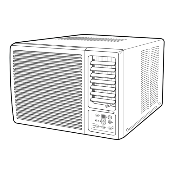
Page 1: Room Air Conditioner
ROOM AIR CONDITIONER AW0690 AW0790 AW0890 AW1090 AW1290 AW1890 SERVICE Manual AIR CONDITIONER CONTENTS 1. Precautions 2. Product Specifications 3. Installation and Operating Instructions 4. Disassembly and Reassembly 5. Troubleshooting 6. Exploded Views and Parts List 7. Block Diagram 8. PCB Diagram SAM0129 9. -
Page 2: Precautions
Relocate the unit if necessary. 9. Keep children away from the unit while it is being repaired. 10. Be sure to clean the unit and its surrounding area. Fig. 1-3 No Kids Nearby! Fig. 1-4 Clean the Unit Samsung Electronics... - Page 3 MEMO Samsung Electronics...
-
Page 4: Product Specifications
Compressor Capacitor µF/ VAC 30/5µF 370VAC 25/5µF 370VAC 35/6µF 370VAC 40/15µF 370VAC 40/15µF 370VAC 35/6µF 450VAC (Dual Type) (Dual Type) (Dual Type) (Dual Type) (Dual Type) (Dual Type) Fan Motor Capacitor µF/ VAC Fan Speed Control HIGH, MID, LOW Samsung Electronics... -
Page 5: Remote Control
Unit : mm Model AW0690 AW0790 AW0890 AW1090 AW1290 AW1890 Front view Side view 2-2-2 Remote Control Temperature adjustment Timer button buttons FAN/COOL mode selection buttons Fan speed adjustment buttons Energy saver button Air Swing button On/Off button Samsung Electronics... -
Page 6: Installation And Operating
Do not use the air conditioner in such areas as a greasy area(including machine oil), saline area(sea side), or sulphuric area(hot spring). When using the air conditioner in these areas, special maintenance is required. Contact your local dealer or our service center for advice. Samsung Electronics... -
Page 7: Function Description
2) Fan motor control in compressor off : After compressor off, the fan motor is operated breeze for 2 minutes and then it turn off. 3) After the fan motor off, the compressor and fan motor is operated normally when the compressor on. Samsung Electronics... - Page 8 If you press the "Increase/Decrease" key of the remote controller, it occurs the alarm horn at above status. - t is possible a single shot and continue operation. - In case of the operation off and flow wind operation, it is treated invalidity. Samsung Electronics...
-
Page 9: Instructions
→ NO. (2) 7 seg. LED display indicates temperature of the units digit In case of time (OFF TIMER) display → NO. (1) 7 seg. LED display indicates time of the tens digit → NO. (2) 7 seg. LED display indicates time of the units digit Samsung Electronics... -
Page 10: Disassembly And Reassembly
Perform soldering function Problem? Fill system with nitrogen gas Check for leakage Leakage? Corrective action Check refrigerant oil level Release nitrogen gas? Low oil level? Evacuate system Add oil as necessary Recharge system Recharge system Samsung Electronics... -
Page 11: Checking The Oil
4. Replacing the refrigerant - Refill 30cc. 5. The high pressure side is filled up with oil after the vacuum is completed. 6. When the refrigerant leaks, it is generally not necessary to refill the oil if the leakage is not severe. Samsung Electronics... -
Page 12: Disassembly And Reassembly Procedure
2. Pull the front both side, and remove the unit from the cabinet. Ass'y Control 1. Remove the blade V and arm blade 2. Remove 2 screws, and 2 earth wire screws. 3. Remove two lead wire assemblies. 4. Take out the control box forward. Samsung Electronics... - Page 13 1. Remove two screws on the bottom side, and Propeller Fan 4 screws on the case cond. 2. Pull up the case cond and separate the cond case from the cond. 3. Remove the nut flange, and remove the pro- peller fan Samsung Electronics...
- Page 14 Disassembly and Reassembly Part name Procedures Remarks Cond Casing 1. Remove the cond casing Blower & Motor 1. Move the motor & blower toward the evap, and lift up the motor & blower from the frame low. Samsung Electronics...
- Page 15 Ass'y Control 1. Remove 6 screws, and earth wire screw. 2. Remove three lead wire assemblies. 3. Remove the blade V and arm blade. 4. Take out the control box forward. Samsung Electronics...
- Page 16 Frame Up 1. Remove 10 screws on the Frame Up. Case Cond & Propeller 1. Remove two screws on the bottom side, and 5 screws on the case cond. 2. Remove the nut flange, and remove the propeller fan Samsung Electronics...
- Page 17 1. Remove two screws on the clip motor, and remove the clip motor. 2. Move the motor & blower toward the evap, and lift up the motor & blower from the frame low. Cond Casing 1. Remove the cond casing Samsung Electronics...
- Page 18 2. Pull the handle on the front side of the bottom, and remove the unit from the cabinet. Ass'y Control 1. Remove 10 screws, on the evap cover and earth wire screw. Samsung Electronics...
- Page 19 1. Remove for screws on the left and right side of the evaporator. Plate - Evap Casing 1. Lift up the evaporator, and remove the tray drain. 2. Remove two screws on the left side of the plate evap casing. 4-10 Samsung Electronics...
- Page 20 1. Remove four hexagon nuts on the base Motor pan. 2. Move the motor - assembly toward the condenser, and lift up the motor - assem- bly from the frame. 3. Remove the clips on both sides carefully using the (-) driver. Samsung Electronics 4-11...
- Page 21 MEMO 4-12 Samsung Electronics...
-
Page 22: Troubleshooting
• Check whether the unit is in "FAN" mode. setting (In "FAN" mode, only the current temperature is displayed, and the desired temperature is not set.) • Checking and Display of Fault Area 7-SEG ERROR OPERATION LED DISPLAY (LE01) ROOM THERMISTOR E1 displayed (OPEN OR SHORT) Samsung Electronics... -
Page 23: Troubleshooting By Symptom
- Is the voltage of DC 5V applied at both ends of and C105. the C105 electrolytic condenser? • Check the IC01, and IC02 for cold Are the IC01(KA7812) and IC02(KA7805) normal? soldering and a short. • Replace the IC01, and IC02. Replace the assembly main PCB. Samsung Electronics... - Page 24 Check the IC08 Is the voltage of the for a short, and IC08 No. 10~16 a replace it. square value? Replace the assembly panel PCB IC04 : Assembly main PCB part. IC07, IC08 : Assembly panel PCB part. Samsung Electronics...
- Page 25 • Replace relevant components. • Check the R414 components. Is the input voltage of the micom(IC04) No. 51 • Check the micom(IC04). pin of the assembly main PCB a aquare wave? Replace the assembly panel PCB. Samsung Electronics...
- Page 26 When the compressor is ON, the RY71 should operat. • Replace the relay. • Check the operation of the O.L.P, and replace it if necessary. Is the compressor normal? • Check the compressor resistance.(0Ω : short, ∞Ω : open) Replace the compressor. Samsung Electronics...
- Page 27 When the air-swing motor is operated, the RY75 should (Normal: About 400Ω) be operated. • Replace the relay. • Check the air-swing motor resistance. Is the air-swing motor normal? (0Ω : short, ∞Ω : open) Replace the air-swing motor. Samsung Electronics...
- Page 28 When the fan motor is Mid, RY73 should operate. • Replace the relay. When the fan motor is Low, RY76 should operate. • Check the fan motor resistance. Is the fan motor normal? (0Ω : short, ∞Ω : open) Replace the fan motor. Samsung Electronics...
-
Page 29: Exploded Views And Parts List
6. Exploded View and Parts List 6-1 Main unit 6-1-1. AW0690/AW0790/AW0890 Samsung Electronics... - Page 30 ASS’Y CONTROL M AW0790 DB93 - 00282C ASS’Y CONTROL M AW0890 DB97 - 30156A ASS’Y ACCESSORY SCREW SACK DB73 - 20135A RUBBER-DRAIN DB67 - 20028A DRAIN-TUBE PP, BLK DB63 - 10365A DB67 - 20043A DRAIN-PAN OUT PP, BLK Samsung Electronics...
- Page 31 6-1-2. AW1090/AW1290 Samsung Electronics...
- Page 32 DB73 - 20042A RUBBER-TUBE NR, -, BLK, - DB94 - 10009A ASS’Y-DRAIN TUBE -, PP BLK DB63 - 10365A -, NR, -, NTR, DB67 - 20019A DRAIN-PAN OUT PP, BLK, -, - DB93 - 00284B ASS’Y REMOCON ARC-701 Samsung Electronics...
- Page 33 6-1-3. AW1890 Samsung Electronics...
- Page 34 ASS’Y SHUTTER GUARD RH ASS’Y DB80 - 10011E INSTALL BRACKET BASE SGCC-A DB80 - 10010E INSTALL BRACKET MOUNT SGCC-A DB73 - 20042A RUBBER TUBE NR, BLK DB94 - 10009A DRAIN TUBE PP, BLK DB63 - 10365A NR, NTR Samsung Electronics...
-
Page 35: Ass'y Control
PD - SM12A - 02 ASS’Y-PCB MAIN ASS’Y DB65 - 10008B CLIP, CAPACITOR SGCC - M 2501 - 001209 C-OIL 25/5µF, 370V 2501 - 001210 C-OIL 30/5µF, 370V 2501 - 001176 C-OIL 35/6µF, 370V DB39 - 20434G C/TOR WIRE ASS’Y Samsung Electronics... - Page 36 ASS’Y DB39 - 20358C C/W DISPLAY AWG 26/18 DB32 - 10051A THERMISTOR 103AT DB64 - 00108A PANEL-CONTROL E HIPS DB64 - 00189A INLAY-CONTROL E DB39 - 10032M POWER CORD 13A, 125V DB39 - 00167B POWER CORD 15A, 125V Samsung Electronics...
- Page 37 DB95 - 20065F ASSY MOTOR SWING M2LJ49ZU32 2501 - 001208 C OIL 35/6µF, 450VAC DB65 - 10008A CLIP CAPACITOR SGCC-M DB66 - 70029A ARM BLADE DB66 - 70024A LEVER DAMPER HIPS DB39 - 00169C POWER CORD 15A, 250V Samsung Electronics...
-
Page 38: Refrigerating Cycle Block Diagram
7. Block Diagram 7-1 Refrigerating Cycle Block Diagram PINCH PIPE (SERVICE VALVE) SUCTION LINE DISCHARGE LINE ACCUMULATOR/COMPRESSOR EVAPORATOR CONDENSER CAPILLARY TUBE PINCH PIPE (SERVICE VALVE) Samsung Electronics... -
Page 39: Basic Structure
Air swing motor Buzzer control Temperature control Power circuit (DC5V) Cool Fan motor control Temp. setting( Power circuit (DC12V) Fan speed (high) Down trans Reset Circuit Fan speed (mid) Power input Fan speed (low) Oscillation Circuit Energy saver Samsung Electronics... - Page 40 RESET IC OUTPUT AVdd KEY-IN2 AVref GRID4 AN10 GRID5 OPTION AN11 OPTION OPTION AN12 OPTION SENSOR THERMISTOR (103AT) AN13 OPTION OPTION AN14 OPTION OPTION AN15 COM. INPUT MODEL & TEMPERATURE OPTION AN16 COM. OUTPUT AN17 KEY-IN1 Vdd1 AVss Samsung Electronics...
-
Page 41: Pcb Diagram
8. PCB Diagram 8-1 Ass’y Main PCB • PD-SM12A-00 / PD-SM12A-01 / PD-SM12A-02 / PD-SM12A-03 • PD-SM12D-00 Samsung Electronics... - Page 42 DE62 - 30031A A6063 W23.5 L31(WHT) BUZZER DE30 - 20016A CSB2220BA BZ61 WIRE-SO COPPER DE39 - 60001A P10.6 SN 52MM J01~J04, OP01 C-CERAMIC DESC 2201 - 000807 102K 400V C702, C703 CONNECTOR WAFER 3711 - 000744 YDW 236-01W CN74 Samsung Electronics...
- Page 43 IC07 LED DISPLAY DE07 - 20028B SSD-A3202GS-A15 LE01 IC-DRIVE DE13 - 20017A KID65003AP IC08 WIRE-SO COPPER DE39 - 60001A PI0.6 SN, T52MM J01~J15 P.C.B-PANEL DE41 - 00101A FR-1, T1.6, W197, L247 ELECTRIC UNIT DE59 - 00004A KSM-313TE5 RM41 Samsung Electronics...
- Page 44 KS51840-39 TR-CHIP A4050-0140 2SC2412K Q1, 2 D-CHIP 32167-662-012 DAP202K, SDS2836 R-CHIP 61079-917-010 1/10 1.0Ω-J R-CHIP 61079-917-331 1/10 330Ω-J C-CHIP A1450-131-101 CL21C 101-J C1, C2 C-CHIP A1453-131-104 CL21C 104-Z SPRING(+) A6674-00C0-0171 NICO SUS ø0.6 SPRING(–) A6674-00C0-0181 NICO SUS ø0.6 Samsung Electronics...
-
Page 45: Wiring Diagrams
AW0790 AC120V 125VAC 14D 271R ˚F 4.7K 1/8W AW0890 AW0890/XAC AC120V 125VAC 14D 271R ˚C 10K 1/8W AW1090 AC120V 125VAC 14D 271R ˚F 4.7K 1/8W AW1290 AW1290/XAC 10K 1/8W ˚C AW1890 AC230V 250VAC 14D 471R ˚F 4.7K 1/8W Samsung Electronics... -
Page 46: Remote Control
9-2 Remote Control Samsung Electronics... - Page 47 If only parts number changes, Just change parts number directly on parts list. And if you need more information, please see the service bulletin Copyright Trademarks © 1995 by Samsung Electronics Co., Ltd. Samsung is a registered trademark and All rights reserved. SyncMaster 17GLi/CMG7387L and MacMaster...
- Page 48 ELECTRONICS © Samsung Electronics Co., Ltd. Apr. 2000. Printed in Korea. Code No. DB81-00162A(1)
Need help?
Do you have a question about the W0690 and is the answer not in the manual?
Questions and answers