Sony BVM-X300 Operating Instructions Manual
Trimaster el 4k professional video monitor
Hide thumbs
Also See for BVM-X300:
- Operating instructions manual (37 pages) ,
- Operating instructions manual (42 pages)

Related Manuals for Sony BVM-X300


Summary of Contents for Sony BVM-X300
-
Page 1: Video Monitor
4-566-075-13(1) Professional Video Monitor Operating Instructions Before operating the unit, please read this manual thoroughly and retain it for future reference. BVM-X300 Software Version 1.0 © 2015 Sony Corporation... - Page 2 Record these numbers in the spaces provided below. Refer to these numbers whenever you call upon your WARNING Sony dealer regarding this product. When installing the unit, incorporate a readily accessible disconnect device in the fixed wiring, or connect the Model No.
- Page 3 This product has been manufactured by or on behalf of 2. Use the Power Cord (3-core mains lead) / Appliance Sony Corporation, 1-7-1 Konan Minato-ku Tokyo, 108- Connector / Plug conforming to the proper ratings 0075 Japan. Inquiries related to product compliance (Voltage, Ampere).
- Page 4 Utilisez l’appareil uniquement avec le For the customers in the U.S.A. chariot, le support, le trépied ou la table SONY LIMITED WARRANTY - Please visit http:// indiqué par le fabricant ou vendu avec www.sony.com/psa/warranty for important l’appareil. Lorsque vous utilisez un chariot, information and complete terms and conditions of faites attention lorsque vous déplacez le chariot et...
- Page 5 Pour les clients en Europe Pour utiliser ce produit en toute sécurité, évitez l’ é coute Ce produit a été fabriqué par ou pour le compte de Sony prolongée à des pressions sonores excessives. Corporation, 1-7-1 Konan Minato-ku Tokyo, 108-0075 Japon.
- Page 6 Für Kunden in Europa obtenir les informations importantes et l’ e nsemble des Dieses Produkt besitzt die CE-Kennzeichnung und termes et conditions de la garantie limitée de Sony erfüllt die EMV-Richtlinie der EG-Kommission. applicable à ce produit. Angewandte Normen: ...
- Page 7 Apparatet må tilkoples jordet stikkontakt Suomessa asuville asiakkaille Laite on liitettävä suojamaadoituskoskettimilla varustettuun pistorasiaan För kunderna i Sverige Apparaten skall anslutas till jordat uttag Інформація для споживачів в Україні. Обладнання відповідає вимогам: – Технічного регламенту обмеження використання деяких небезпечних речовин в електричному та електронному...
-
Page 8: Table Of Contents
Table of Contents Precaution ............9 On Safety ..............9 On Installation ............9 Handling the Screen ..........9 On Burn-in .............. 9 On a Long Period of Use ........10 On High Brightness Display ........ 10 On the Surface of the Unit ........10 On Long Periods of Continuous Use .... -
Page 9: Precaution
(black), always on (red, green, or blue), or flashing. In Precaution addition, over a long period of use, because of the physical characteristics of the organic light-emitting diode, such “stuck” pixels may appear spontaneously. These problems are not a malfunction. On Safety ... -
Page 10: On A Long Period Of Use
On a Long Period of Use Handling and Maintenance of the Screen Due to an OLED’s panel structure and characteristics of materials in its design, displaying static images for The surface of the screen is specially coated to reduce extended periods, or using the unit repeatedly in a high image reflection. -
Page 11: On Fan Error
On Fan Error The unit has a built in fan for cooling. When the fan stops and the (Power) switch indicator blinks in red, turn off the power and contact an authorized Sony dealer. Precaution... -
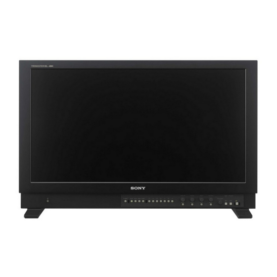
Page 12: Location And Function Of Parts And Controls
Location and Function of Parts and Controls Front Panel (headphones) jack F1 button: [Mono] This is for future function expansion. When expanding F2 button: [Flicker Free] the function, the audio signal which is selected by the F3 button: [Blue Only] input select button is output in stereo sound. - Page 13 MANUAL button: Press to perform the adjustment manually with the knob. Each time the button is If an error display appears, refer to Sony qualified service pressed, the button indicator lights up or goes out. personnel.
-
Page 14: Input Signals And Adjustable/Setting Items
Input Signals and Adjustable/Setting Items Input signal Item SDI 4K SDI 2K Quad Link Dual Link Single Link APERTURE CHROMA BRIGHT CONTRAST User Preset ... -
Page 15: Rear Panel
Rear Panel SDI IN (SDI input) connectors (BNC) VORSICHT Input connectors for serial digital signals. Aus Sicherheitsgründen nicht mit einem Peripheriegerät-Anschluss verbinden, der zu starke For details, see “Connecting the SDI Signals” (page 24). Spannung für diese Buchse haben könnte. Folgen Sie den Anweisungen für diese Buchse. -
Page 16: Connecting The Ac Power Cord
Connecting the AC Power Using the Menu Cord The unit is equipped with an on-screen menu for making various adjustments and settings such as picture Plug the AC power cord into the AC IN socket on control, input setting, set setting change, etc. the rear panel. -
Page 17: Protection Of The Setting Values
Turn the menu selection control to select the item, Protection of the Setting then press the menu selection control. The item to be changed is displayed in yellow. Values If the menu consists of multiple pages, turn the menu selection control to go to the desired menu page. -
Page 18: Adjustment Using The Menus
[Security] Adjustment Using the [Password Lock] [Color Temp./User Pre.] Menus [Change Password] Adjusting and Changing the Settings Items The screen menu of this monitor consists of the [Status] menu following items. The status menu displays the current status of the unit. The following items are displayed: [Status] (the items indicate the current settings.) -
Page 19: [User Preset Setting] Menu
Page 3 Submenu Setting [User Preset] Select the User Preset data to be applied. [User Preset1] [User Preset2] [User Preset3] [User Preset4] [User Preset5] [Color Temp.] Select the color temperature to be used in the selected User Preset. [D65] ... -
Page 20: [User Configuration] Menu
[System Setting] Submenu Setting [Manual Adjustment] If you set the [Color Temp.] to the Submenu Setting [User1] to [User5] setting, you can adjust the color temperature. [LED Brightness] Selects the brightness of the indicator’s The set values are memorized. LED of the buttons, power switch, etc. [Adjust Gain/Bias]: ... - Page 21 [4K/UHD Input Setting] Submenu Setting [Screen Saver] Sets the screen saver function [On] or [Off]. [On]: If a still image is displayed for more than 10 minutes, the brightness of the screen is automatically decreased to reduce burn-in. The screen returns to normal brightness when you input a video signal to the unit or operate the buttons...
- Page 22 [2K/HD Input Setting] Submenu Setting In the HDR display, the cooling fan is forcibly rotated regardless of outside temperature. In the HDR display, the screen saver is forcibly set. [Off] cannot be selected. In the HDR display, [Flicker Free] ...
-
Page 23: Function Button Setting
[Function Button Setting] Submenu Setting Note When [2.4(HDR)], [S-Log3(HDR)], or [S-Log2(HDR)] is selected, HDR (High Dynamic Range) is displayed. The HDR display is a method to faithfully display the brightness of signals defined of 100% or more level without compressing the brightness parts. -
Page 24: [Security] Menu
[Internal Signal Pattern] Connecting the SDI Press the button to change the pattern of the internal signal when the internal signal is displayed. With every Signals press of the button, the picture switches between [White] and [PLUGE]. Single Link 3G/HD-SDI, Dual Link 3G-SDI, and Quad [Internal Signal Setting] Link 3G/HD-SDI signals can be input to the SDI IN connectors of this unit. -
Page 25: Troubleshooting
30 Check if the ventilation slots or vents are blocked with minutes. something such as dust. In this case, refer to Sony qualified service personnel. Input Color is not displayed correctly Check the ... -
Page 26: Available Signal Formats
Always verify that the unit is operating properly 0 °C to 35 °C (32 °F to 95 °F) before use. SONY WILL NOT BE LIABLE FOR Recommended temperature DAMAGES OF ANY KIND INCLUDING, BUT 20 °C to 30 °C (68 °F to 86 °F) - Page 27 Signal System Signal Structure 1280 × 720/50P 4 : 2 : 2 (YCbCr) 10bit 2048 × 1080/30 4 : 2 : 2 (YCbCr) 10bit 2048 × 1080/30 4 : 2 : 2 (YCbCr) 10bit 2048 × 1080/25P 4 : 2 : 2 (YCbCr) 10bit 2048 ×...
- Page 28 Signal System Signal Structure 4 : 4 : 4 (RGB) 10bit 1280 × 720/60 Level-A 4 : 4 : 4 (YCbCr) 10bit 4 : 4 : 4 (RGB) 10bit 1280 × 720/50P Level-A 4 : 4 : 4 (YCbCr) 10bit 4 : 4 : 4 (RGB) 10bit 4 : 4 : 4 (YCbCr)
- Page 29 Signal System Signal Structure 3840 × 2160/25PsF 4 : 2 : 2 (YCbCr) 10bit Square 3840 × 2160/24 4 : 2 : 2 (YCbCr) 10bit Square 3840 × 2160/24 4 : 2 : 2 (YCbCr) 10bit Square 4096 × 2160/30 4 : 2 : 2 (YCbCr) 10bit Square...
- Page 30 Signal System Signal Structure 4 : 4 : 4 (RGB) 10bit 4 : 4 : 4 (YCbCr) 10bit 4096 × 2160/30 Level A/Level B-DL Square 4 : 4 : 4 (RGB) 12bit 4 : 4 : 4 (YCbCr) 12bit 4 : 4 : 4 (RGB) 10bit 4 : 4 : 4 (YCbCr) 10bit...
-
Page 31: Dimensions
Side Dimensions Front Unit: mm (inches) Mass: Approx. 16.0 kg (35 lb 4.4 oz) * Length of M4 screws (rear) Monitor cabinet Attached object Rear 6-M4 hole 6-M4 hole (for the YOKE mount) M4 screw ) to 7 ( Unit: mm (inches) To install on a vehicle, fix the unit using screw holes for the YOKE mount. - Page 32 Sony Corporation...
Need help?
Do you have a question about the BVM-X300 and is the answer not in the manual?
Questions and answers