Table of Contents
Advertisement
Advertisement
Table of Contents

Related Manuals for Focusrite rednet am2


Summary of Contents for Focusrite rednet am2
- Page 1 User Guide www.focusrite.com PRNT001073-01...
-
Page 2: Table Of Contents
RedNet AM2 Connections and Features ........ -
Page 3: About This User Guide
About this User Guide This user guide applies to the RedNet AM2 Dante headphone and line output interface. It provides information about installing and using the unit, and how it can be connected into your system. A RedNet System User Guide is also available from the RedNet product pages of the Focusrite website. -
Page 4: Introduction
INTRODUCTION Thank you for purchasing the Focusrite RedNet AM2. RedNet AM2 provides two channels of premium D-A conversion in the form of a stereo monitoring unit, combining headphone and line outputs for monitoring of signals from the Dante Audio-over-IP network. -
Page 5: Installation Guide
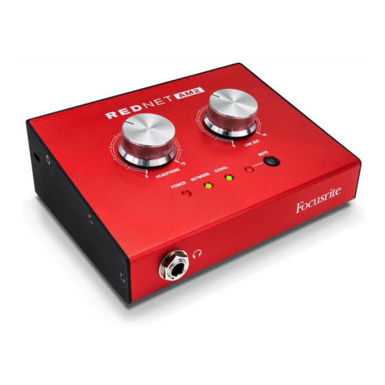
INSTALLATION GUIDE RedNet AM2 Connections and Features Top Panel HEADPHONE LINE OUT POWER NETWORK SIGNAL MUTE Headphone Level Pot Controls the volume level sent to the stereo headphone jack. Line Out Level Pot Controls the volume level sent to the Line Output XLRs. - Page 6 Top Panel . . . Continued HEADPHONE LINE OUT POWER NETWORK SIGNAL MUTE Signal Level Indicator Tri-colour LED indicates the highest signal level of the network receivers: • Green: Signal present (illuminates at -42 dBFS) • Orange: -6 dBFS • Red: 0 dBFS ID Indication –...
-
Page 7: Rear Panel
RJ45 [etherCON] connector for the Dante network. Use standard Cat 5e or Cat 6 network cables to connect RedNet AM2 to an Ethernet network switch. Power over Ethernet (PoE) can be used to power the RedNet AM2. Connect an appropriately powered Ethernet cable to network port 1. -
Page 8: Physical Characteristics
To use the 12 V DC input, connect the external plugtop PSU supplied to an adjacent mains outlet. Only use the DC PSU supplied with RedNet AM2. Use of other external supplies may affect performance or could damage the unit. -
Page 9: Rednet Am2 Operation
Alternatively, if a Network Master is not already present, the unit can be chosen as the Network Master by the user. Pull Up and Pull Down Operation RedNet AM2 is able to operate at a specified pull up or pull down percentage as selected in the Dante Controller application. -
Page 10: Other Rednet System Components
Network Master – Illuminated indicating that this unit is the network master. Reverse ID A Reverse ID request from a RedNet AM2 unit will flash the black background in the device GUI. Signal Metering Both audio channels have a virtual signal level meter. -
Page 11: Id (Identification)
ID (Identification) Clicking on the ID icon will identify the physical device being controlled by cycling its front panel “Network” and “Signal” LEDs through green–orange–red states for 10 seconds. Tools Menu Clicking on the Tools icon will gain access to the following system settings: Line Level Setup –... -
Page 12: Appendix
APPENDIX Connector Pinouts Ethernet Connectors (Dante) Cat 6 Core PoE A PoE B Connector type: RJ-45 (EtherCON) receptacle White + Orange Applies to: NETWORK 1 & 2 Orange White + Green Blue White + Blue Green White + Brown Brown PoE information only applicable to Network port 1 XLR Connectors Signal... -
Page 13: Performance And Specifications
PERFORMANCE AND SPECIFICATIONS Line Level Outputs All measurements taken at +24dBu reference level, maximum gain, R = 100kΩ 0 dBFS Reference Level +18 or +24 dBu (switchable) Frequency Response 20Hz – 20kHz ±0.5dB <-100dB (0.001%) unweighted, 20Hz - 20kHz; -1dBFS input THD + N Dynamic Range 120dB ‘A’-weighted (typical), 20Hz - 20kHz... - Page 14 Front Panel Indicators / Controls LED illuminates Green when PoE is connected and Red when DC power is connected (PoE Power is the default power supply). Green LED: Indicates device is network master or network slave, shows valid network Network lock.
-
Page 15: Focusrite Rednet Warranty And Service
In the event of a Manufacturing Defect becoming evident in a product within 12 months from the date of the original purchase Focusrite will ensure that the product is repaired or replaced free of charge. A Manufacturing Defect is defined as a defect in the performance of the product as described and published by Focusrite.
Need help?
Do you have a question about the rednet am2 and is the answer not in the manual?
Questions and answers