Table of Contents
Advertisement
SERVICE
AIR CONDITIONER
ROOM AIR CONDITIONER
AW126JB/127JB
AW126JE/127JE
AW12A6JD/12A7JD
°C
Manual
CONTENTS
1. Precautions
2. Product Specifications
3. Installation and Operating
Instructions
4. Disassembly and Reassembly
5. Troubleshooting
6. Exploded Views and Parts List
7. Block Diagram
8. PCB Diagram
9. Wiring Diagram
10. Schematic Diagrams
Advertisement
Table of Contents

Related Manuals for Samsung AW127JB


Summary of Contents for Samsung AW127JB
-
Page 1: Room Air Conditioner
ROOM AIR CONDITIONER AW126JB/127JB AW126JE/127JE AW12A6JD/12A7JD SERVICE Manual AIR CONDITIONER CONTENTS 1. Precautions 2. Product Specifications 3. Installation and Operating Instructions 4. Disassembly and Reassembly 5. Troubleshooting 6. Exploded Views and Parts List 7. Block Diagram °C 8. PCB Diagram 9. -
Page 2: Precautions
Relocate the unit if necessary. 9. Keep children away from the unit while it is being repaired. 10. Be sure to clean the unit and its surrounding area. Fig. 1-3 No Kids Nearby! Fig. 1-4 Clean the Unit Samsung Electronics... -
Page 3: Product Specifications
AMAFS100ZTEA AMAFS100ATEB Model Compressor(Rotary) 48A124JV1E1 44B124IW1E6 48A124MV1E5 MRA12030-12008 MRA12008-12008 MRA98706-12008 Overload Protect µF/ VAC Compressor Capacitor 30/450 DUAL TYPE 3.5/450 µF/ VAC Fan Motor Capacitor Fan speed switch(High & Low) Fan Speed Control Thermistor Thermo Control Sleep Timer Samsung Electronics... -
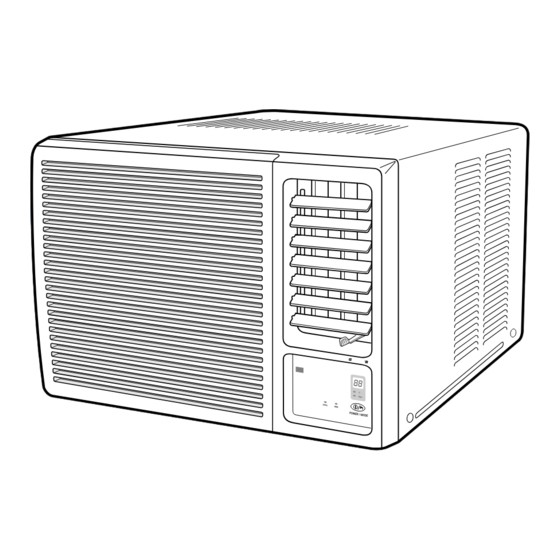
Page 4: Main Unit
Unit : mm Front view Side view °C Hour COOL POWER / MODE 2-2-2 Remote Control Timer setting buttons Mode selection Buttons MODE (FAN, COOL) Temperature adjustment buttons ON/OFF Buttons Fan speed adjustment Buttons Air flow swing button (HIGH, LOW) Samsung Electronics... -
Page 5: Installation And Operating
Do not use the air conditioner in such areas as a greasy area(including machine oil), saline area(sea side), or sulphuric area(hot spring). When using the air conditioner in these areas, special maintenance is required. Contact your local dealer or our service center for advice. Samsung Electronics... -
Page 6: Function Description
"HIGH HIGH"( if Fan speed is selected). 2. The initial FAN speed is set to "HIGH". 3. The set temperature can not be indicated and set. Samsung Electronics... - Page 7 Key name Power/Mode 1. Operation mode change and POWER OFF(in case of model option cooling only) TACT * at every ON - Selected as "OFF –> COOL –> FAN –> OFF". (DEFAULT=OFF) * Continuous operation is not available. Samsung Electronics...
- Page 8 -> NO. (2) 7 seg. LED display indicates temperature of the units digit (˚C, ˚F) In case of time (OFF TIMER) display -> NO. (1) 7 seg. LED display indicates time of the tens digit -> NO. (2) 7 seg. LED display indicates time of the units digit Samsung Electronics...
- Page 9 4.300 19.480 4.444 20.290 4.594 21.150 4.749 22.050 4.912 22.990 5.080 23.900 5.256 25.030 5.439 26.130 5.630 27.280 5.828 28.470 6.033 29.720 6.246 31.040 6.468 32.430 6.699 33.890 6.941 35.430 7.192 37.050 7.455 38.760 7.729 40.560 8.015 8.313 Samsung Electronics...
-
Page 10: Disassembly And Reassembly
Perform soldering function Problem? Fill system with nitrogen gas Check for leakage Leakage? Corrective action Check refrigerant oil level Release nitrogen gas? Low oil level? Evacuate system Add oil as necessary Recharge system Recharge system Samsung Electronics... - Page 11 4. Replacing the refrigerant - Refill 30cc. 5. The high pressure side is filled up with oil after the vacuum is completed. 6. When the refrigerant leaks, it is generally not necessary to refill the oil if the leakage is not severe. Samsung Electronics...
- Page 12 Ass'y Control 1. Remove 6 screws, and earth wire screw. 2. Remove three lead wire assemblies. 3. Remove the blade V and arm blade. 4. Take out the control box forward. Samsung Electronics...
- Page 13 1. Remove 10 screws on the Frame Up. Case Cond & 1. Remove two screws on the bottom side, Propeller Fan and 5 screws on the case cond. 2. Remove the nut flange, and remove the propellr fan Samsung Electronics...
- Page 14 1. Remove two screws on the clip motor, and remove the clip motor. 2. Move the motor & blower toward the evap, and lift up the motor & blower from the frame low. Cond Casing 1. Remove the cond casing Samsung Electronics...
-
Page 15: Troubleshooting
Checking and Display of Fault Area LED LAMP DISPLAY 7-SEG ERROR OPERATION LED DISPLAY COOL ROOM THERMISTOR E1 displayed (OPEN OR SHORT) Lamp --- blinking at every second (on for 0.5s and off for 0.5s) --- LED Lamp off Samsung Electronics... - Page 16 Is the voltage of DC 5V applied at both ends of and C105. the C105 electrolytic condenser? • Check the IC01, and IC02 for cold Are the IC01(KA7812) and IC02(KA7805) normal? soldering and a short. • Replace the IC01, and IC02. Replace the assembly main PCB. Samsung Electronics...
- Page 17 IC03 No. 15~18 a panel PCB. replace it. square wave? Check the IC04 Is the voltage of the for a short, and IC04 No. 10~16 a replace it. square value? Replace the assembly panel PCB Samsung Electronics...
- Page 18 • Replace relevant components. • Check the R202 and C202 components. Is the input voltage of the micom(IC02) No. 26 • Check the micom(IC02). pin of the assembly main PCB a aquare wave? Replace the assembly panel PCB. Samsung Electronics...
- Page 19 When the compressor is ON, the RY71 should operat. • Replace the relay. • Check the operation of the O.L.P, and replace it if necessary. Is the compressor normal? • Check the compressor resistance.(0Ω : short, ∞Ω : open) Replace the compressor. Samsung Electronics...
- Page 20 When the air-swing motor is operated, the (Normal: About 400Ω) RY74 should be operated. • Replace the relay. • Check the air-swing motor resistance. Is the air-swing motor normal? (0Ω : short, ∞Ω : open) Replace the air-swing motor. Samsung Electronics...
- Page 21 When the fan motor is High, RY72 should operate. When the fan motor is Low, RY73 should operate. • Replace the relay. • Check the fan motor resistance. Is the fan motor normal? (0Ω : short, ∞Ω : open) Replace the fan motor. Samsung Electronics...
-
Page 22: Exploded Views And Parts List
6. Exploded View and Parts List 6-1 Main unit Samsung Electronics... -
Page 23: Samsung Electronics
Part List Q'TY Code No. Description Specification Remarks AW126JB AW126JE AW127JE AW126JB AW127JB AW12A6JD AW12A7JD (Mexico) DB64-10145A GRILLE AIR INLET HIPS DB63-30142A GUARD AIR FILTER HIPS DB64-70080A PANEL FRONT HIPS DB66-30169A BLADE-H DB96-40173A ASS’Y EVAP AWH120JE DB90-50133A ASS’Y FRAME LOW... - Page 24 6-2 Ass’y Control Samsung Electronics...
- Page 25 Part List : ASS’Y CONTROL Q'TY Code No. Description Specification Remarks AW126JB AW126JE AW127JE AW126JB AW127JB AW12A6JD AW12A7JD (Mexico) DB98-11178A ASS’Y CONTROL AW126JB DB98-11178C ASS’Y CONTROL AW126JE DB61-10153A CASE CONTROL SECC-P, TO.8 DB66-30170A BLADE-V DB66-70024A LEVER DAMPER HIPS DB66-70022A ARM-BLADE...
- Page 26 6-3 ASS’Y REMOCON(DB93-30056C) Part List Code No. Description Specification Q'TY Remarks DB93-30056B ASS’Y REMOCON ARC-201 DB61-10150A CASE REMOCON(UPP) DB61-10145A CASE REMOCON(LW) DB73-20112B RUBBER(BT) DB93-10516B ASS’Y REMOCON PCB AWH126JE DB74-10084A FILTER-REMOCON DB63-10477A COVER BATTERY DB64-40108B INLAY-FEMOCON Samsung Electronics...
-
Page 27: Block Diagram
7. Block Diagram 7-1 Refrigerating Cycle Block Diagram Capillay tube Check V/V Heat Heat exchanger exchanger (Evaporator) (Condenser) 4-way valve Cooling Heating Compressor Samsung Electronics... - Page 28 • Compressor control • Buzzer control TIMER SETTING( Air swing motor • Temperature control COOL Power circuit (DC 5V) Power circuit (DC 12V) ON/OFF Reset Circuit Down Trans (AC13V ~ AC17V) Oscillation Circuit AIR SWING Power input (AC198V ~ AC264V) Samsung Electronics...
- Page 29 MOD1 SWING MOTOR 10MHz RESONATOR 10MHz RESONATOR NC(OUTPUT PORT) <MODEL OPTION> <TEMPERATURE DISPLAY OPTION> P31(#1) OPTION NOTE P30(#2) OPTION NOTE HIGH COOLING AW126JB(COOLING ONLY) HIGH °C TEMP DISPLAY UNIT LOW HEAT PUMP AWH126JE(HEAT PUMP) °F TEMP DISPLAY UNIT Samsung Electronics...
-
Page 30: Pcb Diagram
8. PCB Diagram 8-1 Main PCB ( ASS'Y CODE NO : DB93-10502A ) Samsung Electronics... - Page 31 RD 1/8 TP 103-F R402, R403 R-CARBON 2001-001172 RD 1/2T 621-J R601 R-CARBON 2001-000003 RD 1/8T 331-J R203, R301, R302, R303 C-CERAMIC 2202-000780 100nF/50V C101, C103 R-CARBON 2001-000290 RD 1/8 103-J R101 R-METAL FILM 2004-001137 RD 1/8 TP 682-F R401 Samsung Electronics...
- Page 32 2001-000003 RD 1/8 TP 331-J R202, R203 C-CERAMIC 2202-000780 100nF/50V C101~C106, C201 C-CERAMIC 2202-000121 101K 0A/50V C202 CERAMIC RESONATOR 2802-000103 10Mhz X501 R-CARBON 2001-000290 RD 1/8 TP 103J R101~R107, 109, R204 IC-MCU MB89635- IC02 DE13-20009A KA7533 DIP IC01 Samsung Electronics...
- Page 33 SI5312-H LDT1 C-ELEC 61079-421-120 50V 4.7uF C-CERAMIC CHIP A4150-131-101 CL21C101J BNCS C-CERAMIC CHIP A4150-131-101 CL21C101J BNCS R-MG CHIP 61079-917-010 RMC 1/10 1.0-J R-MG CHIP 61079-917-564 RMC 1/10 330-J R-MG CHIP 61079-917-331 RMC 1/10 330-J CHIP DIODE 32167-662-012 DAP202K Samsung Electronics...
-
Page 34: Wiring Diagram
9. Wiring Diagram 9-1 AW126JB/127JB CAPACITOR : 3.5/30µF 450VAC POWER SOURCE : 220V~/60Hz 9-2 AW126JE/127JE/12A6JD/12A7JD CAPACITOR : 3.5/30µF 450VAC POWER SOURCE : 200-220V~/50Hz POWER SOURCE : 220-240V~/50Hz Samsung Electronics Samsung Electronics... -
Page 35: Schematic Diagrams
10. Schematic Diagrams 10-1 Main PCB Samsung Electronics 10-1... - Page 36 10-2 Remote Control Samsung Electronics 10-2...
Need help?
Do you have a question about the AW127JB and is the answer not in the manual?
Questions and answers