GE PV977 Owner's Manual And Installation Instructions
Hide thumbs
Also See for PV977:
- Owner's manual and installation instructions (60 pages) ,
- Owner’s manual and installation instruction (54 pages) ,
- Owner's manual & installation instructions (48 pages)
Table of Contents
Advertisement
Available languages
Available languages
Quick Links
Download this manual
See also:
Owner's Manual
Safety Instructions
. . . . . . . . . . . . 2
Operating Instructions
Light Controls . . . . . . . . . . . . . . . . . . . . 4
Vent Controls . . . . . . . . . . . . . . . . . . . . 4
Metal Grease Filter . . . . . . . . . . . . . . . 5
Charcoal Filter . . . . . . . . . . . . . . . . . . . 5
Stainless Steel Surfaces . . . . . . . . . . 6
Light Bulbs . . . . . . . . . . . . . . . . . . . . . . . 6
Installation Preparation . . . . . . . . . . . 8
Vented to the Outside . . . . . . . . . . . 16
Recirculating . . . . . . . . . . . . . . . . . . . . 21
Consumer Support
Warranty . . . . . . . . . . . . . . . . . . . . . . . 29
Consumer Support . . . . . . . . . . . . . . 30
Write the model and serial numbers here:
Model # ______________________
Serial # _______________________
You can find them on a label on the inside
of the hood.
Owner's Manual and
Installation Instructions
. . . . . . . . 27
PV977
49-80550-3 10-15 GE
Advertisement
Chapters
Table of Contents

Related Manuals for GE PV977


Summary of Contents for GE PV977
-
Page 1: Table Of Contents
Consumer Support ....30 Write the model and serial numbers here: Model # ______________________ Serial # _______________________ You can find them on a label on the inside of the hood. 49-80550-3 10-15 GE... -
Page 2: Important Safety Information
IMPORTANT SAFETY INFORMATION. READ ALL INSTRUCTIONS BEFORE USING. This is the safety alert symbol. This symbol alerts you to potential hazards that can kill or hurt you and others. All safety messages will follow the safety alert symbol and the word “DANGER”, “WARNING”, or Indicates a hazardous situation which, if not avoided, will result in death or serious injury. - Page 3 GEAppliances.com SAFETY PRECAUTIONS WARNING – WARNING – TO REDUCE THE RISK OF A TO REDUCE THE RISK OF RANGE TOP GREASE FIRE: FIRE, ELECTRIC SHOCK OR INJURY TO PERSONS, OBSERVE THE FOLLOWING: A. Never leave surface units unattended at high settings. Boilovers cause smoking and greasy spillovers that may A.
- Page 4 Using the hood controls. MEMORY/OFF. HEAT SENSOR: A. Press the MEMORY/OFF button. This hood is equipped with a heat sensor that will turn B. Set your desired fan and light settings. on the fan if excessive temperatures are detected (over C.
-
Page 5: Care And Cleaning
Care and cleaning of the vent hood. GEAppliances.com Be sure electrical power is off and all surfaces are cool before cleaning or servicing any part of the vent hood. Metal Grease Filter To remove: Pull downward on the filter lock to The metal filter traps grease released release the filter. -
Page 6: Stainless Steel Surfaces
G4 base are available at specialty lighting stores and home building centers. To order replacement bulb no. WB01X10239, contact the GE National Parts Center at 1.800.626.2002 or purchase from your local retailer. 5. Replace lamp lens cover by inserting the three retaining tabs into the three slots and pressing firmly in place. -
Page 7: Installation Instructions
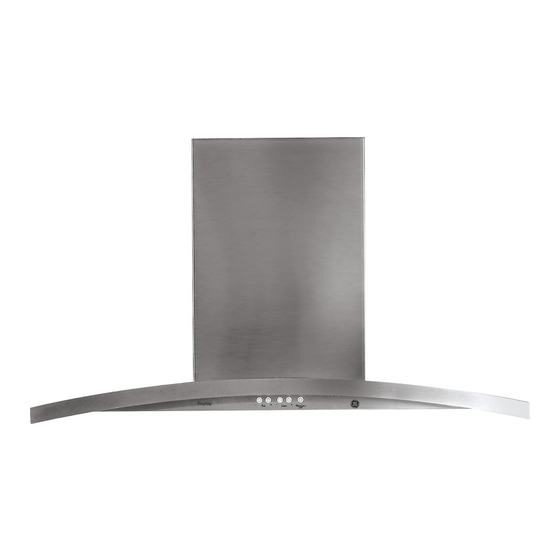
Installation Island Chimney Vent Hood Instructions Questions? Call 800.GE.CARES (800.432.2737) or Visit our Website at: GEAppliances.com BEFORE YOU BEGIN PRODUCT DIMENSIONS Read these instructions completely and carefully. IMPORTANT • Save these instructions for local inspector’s use. IMPORTANT • Observe all governing *Height to codes and ordinances. -
Page 8: Installation Preparation
Installation Preparation PREPARE TO INSTALL THE HOOD ADVANCE PLANNING POWER SUPPLY IMPORTANT - (Please read carefully) Duct Install Planning • Determine the exact location of the vent hood. WARNING: • Use rigid metal ductwork only. • Plan the route for venting exhaust to the outdoors. To maximize the ventilation performance of the Remove house fuse or open circuit breaker before beginning installation. - Page 9 Installation Preparation PREPARE TO INSTALL THE HOOD This Hood Must Use an 8” Round Duct. DO NOT use flexible plastic ducting. NOTE: Any home ventilation system, such as a ventilation hood, may interrupt the proper flow of combustion air and exhaust required by fireplaces, gas furnaces, gas water heaters and other naturally vented systems.
- Page 10 Installation Preparation PREPARE TO INSTALL THE HOOD TOOLS AND MATERIALS REQUIRED REMOVE THE PACKAGING (NOT SUPPLIED) CAUTION: Wear gloves to protect against sharp edges. • Remove the duct covers. Safety glasses • Remove the hardware bag, literature package and other boxed parts. Pencil and tape measure •...
-
Page 11: Recirculating
Installation Preparation PREPARE TO INSTALL THE HOOD CHECK INSTALLATION HARDWARE Locate the hardware package packed with the hood and check contents. HARDWARE PACKAGE Locate and count Upper vertical supports (4) screws 4 Wood screws 4 Duct cover clips Lower vertical supports (4) 73 Hood attachment screws (70 required, 3 extra) Duct cover supports (2) - Page 12 Installation Preparation PREPARE TO INSTALL THE HOOD INSTALLATION CLEARANCES These vent hoods are designed to be installed onto a wall with no above cabinets. • Install these hoods between the required 24” minimum and 36” recommended maximum above the cooking surface. 24”...
- Page 13 Installation Preparation PREPARE TO INSTALL THE HOOD CONSTRUCT CEILING SUPPORT Plan the Location of the Hood and Ductwork Ceiling • Use a plumb bob to check the location. Duct covers must be centered with the hood. Hood • The hood should extend beyond the front and rear ducting centerline edge of the cooking appliance.
- Page 14 Installation Preparation PREPARE TO INSTALL THE HOOD CONSTRUCT CEILING SUPPORT (Continued) EXAMPLE B Install cross-framing 2x4 Cross framing wood cooktop centerline 16” Joist supports spacing 8” Duct Front Cooktop Align duct outline to center hood of cooktop Top view – ceiling joists run perpendicular to front of hood EXAMPLE C 2x4 Cross framing wood...
- Page 15 Installation Preparation PREPARE TO INSTALL THE HOOD CONSTRUCT CEILING SUPPORT (Continued) 2 x 4 min. Cross framing • Secure each 2 x 4 block with at least four (4), #10 wood screws, 3” long (not supplied). Use 8 wood screws total for the two supports. •...
- Page 16 Installation Preparation STEP 1 MOUNT TEMPLATE • Align the template with the marks on the ceiling and tape in place. – Be sure the template is oriented correctly Drill 3/16" Pilot Holes Approx. 1-1/2" Deep 4 Places with the front of the hood. 10-5/16"...
- Page 17 Installation Preparation STEP 4 DETERMINE FRAME HEIGHT STEP 5 INSTALL UPPER VERTICAL SUPPORTS TO HOOD ASSEMBLY •Measure exact Frame • Determine how much of the upper vertical ceiling height. height supports will need to be above the lower supports Ceiling •...
- Page 18 Installation Preparation STEP 6 CUT DUCT TO LENGTH STEP 7 INSTALL HOOD ASSEMBLY FOR VENTED INSTALLATION TO CEILING SUPPORT WARNING: • Measure from the hood exhaust opening to Two people are required the top of the supports as shown in the figure. to lift and position the hood onto the support.
- Page 19 Installation Preparation STEP 8 CONNECT ELECTRICAL STEP 9 INSTALL DUCT COVER SUPPORTS Verify that power is turned off at the source. • Attach the duct cover supports to the sides of the horizontal and ceiling supports using WARNING: If house wiring is not 2-wire 4 screws per duct cover support.
- Page 20 Installation Preparation STEP 10 INSTALL DUCT COVERS STEP 10 INSTALL DUCT COVERS (CONT.) IMPORTANT: Two people are required to install • Using screws provided, secure the lower duct the duct covers. covers to the hood assembly from the underside NOTE: If you are installing this hood for recirculating of the hood.
- Page 21 Installation Preparation STEP 3 INSTALL CEILING SUPPORT STEP 1 MOUNT TEMPLATE AND DEFLECTOR ASSEMBLY • Align the template with the marks on the ceiling and tape in place. • Using the 4 wood screws provided, attach the – Be sure the template is oriented correctly ceiling support using the pilot holes drilled in step 1.
- Page 22 Installation Preparation STEP 5 DETERMINE FRAME HEIGHT STEP 6 INSTALL UPPER VERTICAL SUPPORT •Measure exact • Using the screws provided, attach the 4 upper Frame ceiling height. vertical supports to the lower vertical supports height Ceiling • Find the exact at the position determined for frame height.
- Page 23 Installation Preparation STEP 7 DETERMINE DUCT LENGTH STEP 8 INSTALL HOOD ASSEMBLY AND INSTALL DUCT TO CEILING SUPPORT WARNING: • Measure from the hood exhaust opening to Two people are required the top of the supports as shown in the figure. to lift and position the hood onto the support.
- Page 24 Installation Preparation STEP 9 CONNECT ELECTRICAL STEP 10 INSTALL DUCT COVER SUPPORTS Verify that power is turned off at the source. • Attach the duct cover supports to the sides of the horizontal and ceiling supports using 4 screws per WARNING: If house wiring is not 2-wire duct cover support.
- Page 25 Installation Preparation STEP 11 INSTALL DUCT COVERS (cont.) STEP 11 INSTALL DUCT COVERS • Place a duct cover clip onto the bottom of the IMPORTANT: Two people are required to install rear lower duct cover locking the clip into place. the duct covers.
- Page 26 Installation Preparation STEP 12 INSTALL FILTERS Charcoal Filter Insert the charcoal filter into the opening. Push the latch on both sides toward the center and engage the flange. Metal Grease Filter • Remove the protective film on the grease filter. •...
-
Page 27: Troubleshooting Tips
• This hood requires 8” minimum ducting to perform airflow noise installation. optimally. Using smaller duct pipe will cause improper venting. GE service technicians cannot correct this issue if installed improperly. Fan fails to circulate air Obstructions in duct work. -
Page 28: Before You Call For Service
Before you call for service… Troubleshooting Tips Save time and money! Review the chart below first and you may not need to call for service. Problem Possible Causes What To Do Fan turned on by itself The heat sensor is activated. •... -
Page 29: Warranty
GE at the time of service. For the period of one year from the date of the original purchase. GE will provide any part of the range which fails due to a defect in materials or workmanship. During this limited one-year warranty, GE will also provide, free of charge, all labor and in-home service to replace the defective part. -
Page 30: Consumer Support
Caution must be exercised, since improper servicing may cause unsafe operation. Contact Us GEAppliances.com If you are not satisfied with the service you receive from GE, contact us on our Website with all the details GE Appliances, Appliance Park Register Your Appliance GEAppliances.com Timely product registration will allow for enhanced communication and prompt service under the terms of your warranty, should the need arise. - Page 31 Apoyo al cliente ....30 Escriba los números de modelo y de serie aquí: Modelo # _____________________ Serie # _______________________ Usted puede encontrarlos en una etiqueta ubicada en la parte interna de la campana. 49-80550-3 10-15 GE...
-
Page 32: De Seguridad
INFORMACIÓN IMPORTANTE DE SEGURIDAD. LEA TODAS LAS INSTRUCCIONES ANTES DE SU USO. Éste es el símbolo de alerta de seguridad. El mismo alerta sobre potenciales riesgos de muerte o lesiones tanto para usted con para otras personas. Todos los mensajes de seguridad estarán a continuación del símbolo de alerta de seguridad y con la palabra “PELIGRO”, “ADVERTENCIA”... - Page 33 GEAppliances.com PRECAUCIONES DE SEGURIDAD ADVERTENCIA – ADVERTENCIA – PARA REDUCIR EL RIESGO PARA REDUCIR EL RIESGO DE UN INCENDIO DE GRASA SOBRE UNA ESTUFA: DE INCENDIO, DESCARGA ELÉCTRICA O LESIONES A A. Nunca deje unidades de superficie desatendidas en PERSONAS, CUMPLA CON LOS SIGUIENTES PUNTOS: configuraciones de calor elevadas.
- Page 34 Cómo usar los controles de la campana. MEMORY/OFF (memoria/apagado). SENSOR DE CALOR: Para configurar la memoria: Esta campana cuenta con un sensor de calor que enciende A. Presione el botón MEMORY/OFF. el ventilador si se detectan temperaturas excesivas (más de B.
- Page 35 Cuidado y limpieza de la campana de ventilación. GEAppliances.com Asegúrese de que la energía eléctrica esté apagada y que todas las superficies estén frías antes de limpiar o arreglar cualquier pieza de la campana de ventilación. Filtro de grasa metálico Para quitar: Tire hacia abajo la traba del filtro para El filtro metálico atrapa la grasa...
- Page 36 NOTA: Asegúrese de que las lengüetas estén colocadas en las ranuras. disponibles en tiendas especializadas en iluminación y centros de construcción. Para solicitar una bombilla de repuesto N° WB01X10239, comuníquese con el Centro nacional de piezas GE al 800.626.2002 o adquiérala en su minorista local. 49-80550-3...
-
Page 37: De Instalación
Instrucciones Campanas de ventilación de instalación de chimenea para isla ¿Preguntas? Llame al 800.GE.CARES (800.432.2737) o visite nuestro sitio Web en: GEAppliances.com ANTES DE COMENZAR DIMENSIONES DEL PRODUCTO Lea estas instrucciones por completo y con 13-1/8” detenimiento. IMPORTANTE • Guarde estas instrucciones para el uso de inspectores locales. -
Page 38: Preparación Para La Instalación
Preparación para la instalación PREPARACIÓN PARA INSTALAR LA CAMPANA SUMINISTRO DE ENERGÍA PLANIFICACIÓN PREVIA IMPORTANTE – (Tenga a bien leer cuidadosamente) Planificación para la Instalación con Conducto ADVERTENCIA: • Determine la ubicación exacta de la campana de ventilación. PARA SEGURIDAD PERSONAL, ESTE APARATO DEBE •... - Page 39 Preparación para la instalación PREPARACIÓN PARA INSTALAR LA CAMPANA Esta campana debe usar un conducto redondo de 8”. Puede conectarse a un conducto de 3-1/4” x 12”. NO USE conductos flexibles de plástico. NOTA: Cualquier sistema de ventilación doméstico, como una campana de ventilación, puede interrumpir el flujo adecuado de aire de combustión y de escape requerido para chimeneas, hornos a gas, calentadores de...
- Page 40 Preparación para la instalación PREPARACIÓN PARA INSTALAR LA CAMPANA HERRAMIENTAS Y MATERIALES QUITE EL ENVOLTORIO REQUERIDOS PRECAUCIÓN: (NO SUMINISTRADOS) Se guantes para protegerse de los bordes afilados. • Quite las cubiertas de los conductos. Gafas de seguridad • Quite la bolsa de piezas, el paquete de instrucciones y otras piezas en cajas.
- Page 41 Preparación para la instalación PREPARACIÓN PARA INSTALAR LA CAMPANA CONTROLE LAS PIEZAS DE INSTALACIÓN Ubique el paquete de hardware embalado con la campana y verifique los contenidos. PAQUETE DE HARDWARE Soportes verticales Ubique y cuente los superiores (4) tornillos Soportes verticales 4 ganchos de la inferiores (4) cubierta del conducto...
- Page 42 Preparación para la instalación PREPARACIÓN PARA INSTALAR LA CAMPANA ESPACIO DE INSTALACIÓN Estas campanas de ventilación están diseñadas para ser instaladas en una pared sin gabinetes superiores. • Instale estas campanas entre el mínimo requerido de 24” y el máximo recomendado de 36”...
- Page 43 Preparación para la instalación PREPARACIÓN PARA INSTALAR LA CAMPANA CONSTRUYA EL SOPORTE DEL CIELORRASO Planifique la ubicación de la campana Cielorraso y del conducto • Utilice una plomada para verificar la ubicación. Cubiertas El mostrador de encimera/la estufa debajo de del conducto Línea central la campana deben centrarse respecto de la...
- Page 44 Preparación para la instalación PREPARACIÓN PARA INSTALAR LA CAMPANA CONSTRUYA EL SOPORTE DEL CIELORRASO (continuación) Instale el armazón cruzado en EJEMPLO B forma simétrica sobre la línea Soportes de madera del central del conducto/estufa armazón cruzado de 2 Espacio para viga 10-5/16”...
- Page 45 Preparación para la instalación PREPARACIÓN PARA INSTALAR LA CAMPANA CONSTRUYA EL SOPORTE DEL CIELORRASO Armazón cruzado (continuación) de 2 x 4 mín. • Fije cada bloque de 2 x 4 con por lo menos cuatro (4) tornillos para madera N°10 de 3” de longitud (no provistos).
- Page 46 Preparación para la instalación PREPARACIÓN PARA INSTALAR LA CAMPANA PASO 1 COLOQUE LA PLANTILLA • Alinee la plantilla con las marcas sobre el cielorraso y adhiera en su lugar con cinta. – Asegúrese de que la plantilla esté bien orientada Perfore orificios piloto de 3/16"...
- Page 47 Preparación para la instalación PREPARACIÓN PARA INSTALAR LA CAMPANA PASO 4 DETERMINE LA ALTURA PASO 5 INSTALE LOS SOPORTES DEL ARMAZÓN VERTICALES SUPERIORES EN EL MONTAJE DE LA CAMPANA •Mida la altura Altura del exacta del • Determine qué cantidad de los soportes verticales armazón Altura del cielorraso.
- Page 48 Instrucciones de instalación PASO 6 CORTE EL CONDUCTO CON PASO 7 INSTALE EL MONTAJE DE LA LONGITUD PARA UNA LA CAMPANA EN EL SOPORTE INSTALACIÓN VENTILADA DEL CIELORRASO ADVERTENCIA: • Mida desde la abertura de escape de la campana Se necesitan hasta la parte superior de los soportes como dos personas para levantar y colocar la campana puede verse en la figura.
- Page 49 Instrucciones de instalación PASO 8 CONECTE LOS ELEMENTOS PASO 9 INSTALE LOS SOPORTES ELÉCTRICOS DE LA CUBIERTA DEL CONDUCTO Verifique que la energía esté cortada en la fuente. • Sujete los soportes de la cubierta del conducto a los costados de los soportes horizontales ADVERTENCIA: Si el cableado y de cielorraso usando 4 tornillos por soporte.
- Page 50 Instrucciones de instalación PASO 10 INSTALE LAS CUBIERTAS PASO 10 INSTALE LAS CUBIERTAS DEL CONDUCTO DEL CONDUCTO (cont.) IMPORTANTE: Se necesitan dos personas para • Usando los tornillos provistos, fije las cubiertas instalar las cubiertas del conducto. NOTA: Si va a instalar esta campana para una del conducto inferiores al montaje de la campana operación de recirculación, coloque las cubiertas desde la parte inferior de la campana.
-
Page 51: Recirculación
Instrucciones de instalación PASO 3 INSTALE EL MONTAJE PASO 1 COLOQUE LA PLANTILLA DEL SOPORTE DEL CIELORRASO • Alinee la plantilla con las marcas sobre el cielorraso Y DEFLECTOR y adhiera en su lugar con cinta. – Asegúrese de que la plantilla esté bien orientada •... - Page 52 Instrucciones de instalación PASO 5 DETERMINE LA ALTURA PASO 6 INSTALE EL SOPORTE VERTICAL DEL ARMAZÓN SUPERIOR •Mida la altura • Utilizando los tornillos provistos, sujete los exacta del Altura del 4 soportes verticales superiores a los soportes cielorraso. armazón Altura del verticales inferiores en la posición determinada cielorraso...
- Page 53 Instrucciones de instalación PASO 7 DETERMINE LA LONGITUD PASO 8 INSTALE EL MONTAJE DE DEL CONDUCTO E INSTÁLELO LA CAMPANA EN EL SOPORTE DEL CIELORRASO • Mida desde la abertura de escape de la campana hasta la parte superior de los soportes como ADVERTENCIA: Se necesitan dos puede verse en la figura.
- Page 54 Instrucciones de instalación PASO 9 CONECTE LOS ELEMENTOS PASO 10 INSTALE LOS SOPORTES ELÉCTRICOS DE LA CUBIERTA DEL CONDUCTO Verifique que la energía esté cortada en la fuente. ADVERTENCIA: • Sujete los soportes de la cubierta del conducto Si el cableado a los costados de los soportes horizontales doméstico no cuenta con un cable de 2 hilos con y de cielorraso usando 4 tornillos por soporte.
- Page 55 Instrucciones de instalación PASO 11 INSTALE LAS CUBIERTAS PASO 11 INSTALE LAS CUBIERTAS DEL CONDUCTO (cont.) DEL CONDUCTO • Coloque un gancho de la cubierta del conducto IMPORTANTE: Se necesitan dos personas para instalar en la parte inferior de la cubierta del conducto las cubiertas del conducto.
- Page 56 Instrucciones de instalación PASO 12 INSTALE LOS FILTROS Filtro de carbón Introduzca el filtro de carbón dentro de la abertura. Presione la traba sobre ambos lados hacia el centro y sujete la brida. Filtro de grasa metálico • Quite la película protectora del filtro de grasa. •...
-
Page 57: Consejos Para La Identificación Y Solución De Problemas
8” para funcionar de manera óptima. El uso de un conducto más pequeño hará que se ventile de forma inadecuada. Los técnicos de GE no pueden corregir este problema si hay una instalación inadecuada. El ventilador no hace Obstrucciones en el conducto. - Page 58 Antes de llamar al servicio técnico… Consejos para identificación y solución de problemas ¡Ahorre tiempo y dinero! Lea la siguiente tabla primero y quizás no necesite llamar al servicio técnico. Problema Causas posibles Qué hacer El ventilador se encendió Se encuentra activado el sensor • Esto es normal cuando las temperaturas debajo de solo y se encuentra en la de calor.
- Page 59 GE en el momento del servicio. Durante el período de un año desde la fecha original de compra. GE le brindará cualquier parte de la cocina que falle debido a un defecto en los materiales o la fabricación. Durante esta garantía limitada de un año, GE también proveerá, sin costo, todo el trabajo y el servicio en el hogar relacionado con el reemplazo de la parte que presente defectos.
-
Page 60: Garantía
Solicite una reparación GEAppliances.com El servicio de expertos GE está a tan sólo un paso de su puerta. ¡Entre en línea y solicite su reparación cuando le venga cualquier día del año! O llame al 800.GE.CARES (800.432.2737) durante horas normales de oficina.
Need help?
Do you have a question about the PV977 and is the answer not in the manual?
Questions and answers