Table of Contents
Advertisement
INSTRUCTIONS
DP30BW
MICROSCOPE DIGITAL CAMERA
This instruction manual is for the Olympus DP30BW Microscope Digital Camera. To ensure the
safety, obtain optimum performance and familiarize yourself fully with the use of this camera, we
recommend that you study this manual thoroughly before operating the camera.
For image operations including recording, editing and saving, please refer to the Online Help for
the DP-BSW Basic Software.
Retain this instruction manual in an easily accessible place near the work desk for future reference.
A X 7 2 9 1
This publication is printed on 100% recycled paper
Advertisement
Table of Contents

Subscribe to Our Youtube Channel
Related Manuals for Olympus DP30BW


Summary of Contents for Olympus DP30BW
- Page 1 DP30BW MICROSCOPE DIGITAL CAMERA This instruction manual is for the Olympus DP30BW Microscope Digital Camera. To ensure the safety, obtain optimum performance and familiarize yourself fully with the use of this camera, we recommend that you study this manual thoroughly before operating the camera.
- Page 2 NOTE: This equipment has been tested and found to comply with the limits for a Class A digital device, pursuant to Part 15 of the FCC Rules. These limits are designed to provide reasonable protection against harmful interference when the equipment is operated in a commercial environment. This equipment generates, uses, and can radiate radio frequency energy and, if not installed and used in accordance with the instruction manual, may cause harmful interference to radio communications.
-
Page 3: Table Of Contents
DP30BW CONTENTS IMPORTANT — Be sure to read this chapter for safe use of the equipment. — SYSTEM CHART NOMENCLATURE HARDWARE INSTALLATION ..................................Installing the Boards ..............................Installing the Camera Head SOFTWARE INSTALLATION 10-16 ..............................Installing the Device Driver 10-14 ........................... -
Page 4: Important - Be Sure To Read This Chapter For Safe Use Of The Equipment
4. The camera head is as heavy as 3 kilograms. Be careful not to drop it when mounting or transporting it. Store it with the C-mount section facing down because it tends to roll easily. 5. The camera head of the DP30BW incorporates the shutter. Since the shutter is a precision component, it should never be touched by hand to prevent malfunction. - Page 5 U-ULC-2 ultralow-magnification condenser is used. 5. When the DP30BW is connected to the rear port of the U-DPT or U-MPH, the peripheral part of the image may be deteriorated due to the optical performance of the U-DPT or U-MPH.
- Page 6 The adjacent slot can be used to mount the trigger IO board. 3. CPU Olympus does not guarantee operation if the PC uses a CPU other than Pentium 4 or a chipset other than an Intel chipset. 4. PCI board installation in other slots The PCI board can be used simultaneously with an SCSI card or LAN card.
-
Page 7: Getting Ready
Data Storage Caution Recorded picture data may be lost (or destroyed) in any of the following cases. Please note that Olympus assures no liability for loss of recorded data. The user is recommended to back up the recorded data periodically. -
Page 8: System Chart
Trigger IO board External shutter, etc. (Model connected via BNC cable) ATX power supply Basic software (CD-ROM) Cable DP-BSW Microscope Digital connection Camera DP30BW Interface cable PCI Interface board Camera head Monitor Computer U-CMAD3 C-Mount Camera U-PMTVC U-CMT Adapter C-Mount... -
Page 9: Nomenclature
DP30BW NOMENCLATURE Any equipment connected to the camera head should be an Olympus-designated product or a Camera Head product in compliance with the requirements of IEC60950 or CISPR22-24. If equipment other than these products is connected, Olympus cannot guarantee any performance of the camera. -
Page 10: Hardware Installation
HARDWARE INSTALLATION Installing the Boards (Figs. 1 & 2) # Be sure to read the instruction manual for the PC in order not to damage the PC and PCI interface board. # Be sure to turn off the PC and peripherals and unplug their power cords before installing the PCI interface board. -
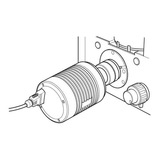
Page 11: Installing The Camera Head
DP30BW Installing the Camera Head (Figs. 3 to 5) }This section describes the procedure using the combination of the U-TV1X-2 TV adapter + U-CMAD3 C-mount camera adapter. 1. Screw in the U-CMAD3 C-mount camera adapter @ into the C-mount thread on the bottom of the camera head ². - Page 12 }The DP-TRAD tripod adapter is provided with two types of screws (2 each) and an Allen wrench. Use only the Phillips screws (x 2) with the DP30BW. 1. Insert the Philips screws ² into the DP-TRAD tripod adapter @ and, without tilting the tripod adapter, place it in position in the insertion slot ³.
-
Page 13: Software Installation
DP30BW SOFTWARE INSTALLATION Installation of the optionally available basic software for the DP30BW “DP-BSW" is described below. Before Installation When the OS is Windows The application software cannot be installed unless the user account is registered as “computer administrator”. If the user account is registered as a “Restricted account”, change it to the “Computer administrator” account. - Page 14 12. When the [Control Panel] dialog box is displayed, click on [Performance and Maintenance]. When the Olympus software is searched, a message is displayed indicating that it is not Microsoft-authorized software. As there is no problem, just continue.
- Page 15 DP30BW 14. When the [System Properties] dialog box is displayed, click 15. If the driver has been properly installed, “MalAd Device” on the [Hardware] tab and then click on the <Device Man- should be displayed as shown below. After confirming this, ager>...
- Page 16 10. Click on the [Next] button. 8. Click on the [Look in] pull-down menu to open it and select [DPBSW]. Then, double click on [Drivers] – > [Win2000], and click on the [Open] button. 11. Click on the [Finish] button. 12.
- Page 17 DP30BW 15. When the [System Properties] dialog box is displayed, click 16. If the driver has been properly installed, “MalAd Device” on the [Hardware] tab and click on the <Device Manager> should be displayed as shown below. After confirming this, button.
-
Page 18: Installing The Application Software
[Next] button. a) DP70/DP30BW Application Program Checking this installs the application software, which allows you to control the DP30BW for recording images 5. Before proceeding to installation, close all running and manage the images in a simplifier manner using applications. - Page 19 DP30BW 9. The [Select Program Folder] window appears. If you want 11. When the installation completes, click on the [Finish] to change the program folder, change the name under button. [Program Folders] or select a folder under [Existing Folders]. Then click on the [Next] button.
-
Page 20: Image Recording Procedure
IMAGE RECORDING PROCEDURE Image recording procedure using the optionally available basic software for the DP30BW “DP-BSW" is describe below. (Note) The encircled numbers indicate the control positions in the windows shown on the next page. For detailed operating procedures, refer to the Online Help of the DP Controller and DP Manager. -
Page 21: Displayed Windows
DP30BW DISPLAYED WINDOWS Image Record Window }This window is displayed at the startup and used to record still images and movies. For details, refer to the Online Help of the DP Controller. The Online help can be viewed by opening the [Help] menu and selecting [Help]. -
Page 22: External Triggering
EXTERNAL TRIGGERING }The DP30BW can input or output an external trigger signal to record still images or control a commercially available shutter. Connecting the BNC triggering cable 1. Turn off the PC. 2. When using the external trigger input, connect the BNC cable’s connector ³... - Page 23 DP30BW Operation using the trigger output · The trigger signal output from the DP30BSW can be used to control a commercially available high-speed shutter. · Use a shutter, the minimum opening time of which is faster than the exposure time for shooting.
-
Page 24: Specifications
SPECIFICATIONS Item Specifications Camera system Single CCD black-and-white camera. Shutter built in Image pickup device 2/3 in. black-and-white CCD 1.50 Megapixels (Total pixels) 1.45 Megapixels (Effective pixels) Progressive scanning. Cooling system Peltier device cooling + Natural air cooling. CCD temperature: Constant at 5°C Image sizes 1360 x 1024 (1x1) 680 x 512 (1x1) -
Page 25: Specifications
DP30BW Item Specifications Image display speed 1360 x 1024: 15 fps. (Frame rate) 680 x 510(2x2): 29 fps. 340 x 250(4x4): 53 fps. 170 x 120(8x8): 53 fps. (Maximum) Image file formats# TIFF (16/8-bit), JPEG, BMP, PICT, AVI, MPEG-1 Interface PCI bus interface: PCI Rev. -
Page 26: Maintenance
MAINTENANCE Cleaning the Dustproof Glass in the Camera Head 1. Remove the camera head from the TV adapter. Keep the interface cable connected and confirm that the clamping screws of the connector are tightened. Clearance 2. Start the DP Controller. This will release the built-in shutter and expose the dustproof glass. - Page 27 DP30BW Calibrating the Camera }Since the camera level setting varies as time passes, it should be calibrated every year using the following procedure. 1. Select the [Image Quality] tab on the DP Controller and 3. Click the [Next] button. Camera calibration will start.
-
Page 28: Troubleshooting Guide
Under certain conditions, the performance of the camera may be adversely affected by factors other than defects. If problems occur, please review the following list and take remedial action as needed. If you cannot solve the problem after checking the entire list, please contact Olympus for assistance. Problem... - Page 29 DP30BW Problem Cause Page Remedy The input highlight level adjustment is Reset the current level adjustment (Online too low. and adjust the optimum level again. manual) The microscope illumination is too Reduce the microscope illumination bright. intensity or engage an ND filter to –...
-
Page 30: Software Uninstallation
3. When the [Add or Remove Programs] window appears, select [OLYMPUS MICRO DP70/DP30VW] under [Currently installed programs] and click on the [Change/Remove] button. 4. When the [OLYMPUS MICRO DP70/DP30BW] window appears, select [Remove] and click on the [Next] button. 5. When the [Confirm File Deletion] window appears, click on the [OK] button. - Page 31 2-43-2, Hatagaya, Shibuya-ku, Tokyo, Japan Postfach 10 49 08, 20034, Hamburg, Germany 2 Corporate Center Drive, Melville, NY 11747-3157, U.S.A. One Corporate Drive, Orangeburg, NY 10962, U.S.A. 491B River Valley Road, #12-01/04 Valley Point Office Tower, Singapore 248373 2-8 Honduras Street, London EC1Y OTX, United Kingdom. 31 Gilby Road, Mt.
Need help?
Do you have a question about the DP30BW and is the answer not in the manual?
Questions and answers