Table of Contents
Advertisement
Available languages
Available languages
Safe Operation Practices • Set-Up • Operation • Maintenance • Service • Troubleshooting • Warranty
O
'
M
peratOr
s
anual
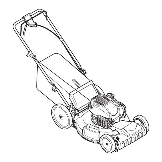
Self Propelled Mower — Model 1696607
WARNING
READ AND FOLLOW ALL SAFETY RULES AND INSTRUCTIONS IN THIS MANUAL
BEFORE ATTEMPTING TO OPERATE THIS MACHINE.
FAILURE TO COMPLY WITH THESE INSTRUCTIONS MAY RESULT IN PERSONAL INJURY.
Briggs & Stratton Power Products Group, LLC • 12301 West Wirth St. • Wauwatosa • WI 53222
Printed In USA
Form No. 769-10314
(October 31, 2014)
Advertisement
Chapters
Table of Contents

Related Manuals for Snapper washer-extractor


Summary of Contents for Snapper washer-extractor
- Page 1 Safe Operation Practices • Set-Up • Operation • Maintenance • Service • Troubleshooting • Warranty ’ peratOr anual Self Propelled Mower — Model 1696607 WARNING READ AND FOLLOW ALL SAFETY RULES AND INSTRUCTIONS IN THIS MANUAL BEFORE ATTEMPTING TO OPERATE THIS MACHINE. FAILURE TO COMPLY WITH THESE INSTRUCTIONS MAY RESULT IN PERSONAL INJURY.
-
Page 2: Table Of Contents
If you have any problems or questions concerning the machine, It instructs you how to safely and easily set up, operate and phone a authorized Snapper service dealer or contact us directly. maintain your machine. Please be sure that you, and any other Snapper’s Customer Support telephone number, website address... -
Page 3: Safe Operation Practices
Important Safe Operation Practices WARNING: This symbol points out important safety instructions which, if not followed, could endanger the personal safety and/or property of yourself and others. Read and follow all instructions in this manual before attempting to operate this machine. Failure to comply with these instructions may result in personal injury. - Page 4 A missing or damaged discharge cover can cause blade When starting engine, pull cord slowly until resistance contact or thrown object injuries. is felt, then pull rapidly. Rapid retraction of starter cord (kickback) will pull hand and arm toward engine faster than Many injuries occur as a result of the mower being pulled you can let go.
- Page 5 Service Check the blade and engine mounting bolts at frequent intervals for proper tightness. Also, visually inspect blade Safe Handling Of Gasoline: for damage (e.g., bent, cracked, worn) Replace blade with the original equipment manufacture’s (O.E.M.) blade only, To avoid personal injury or property damage use extreme listed in this manual.
-
Page 6: Spark Arrestor
Notice Regarding Emissions Power Ratings Engines which are certified to comply with California and federal The gross power rating for individual gas engine models EPA emission regulations for SORE (Small Off Road Equipment) is labeled in accordance with SAE (Society of Automotive are certified to operate on regular unleaded gasoline, and Engineers) code J1940 Small Engine Power &... -
Page 7: Safety Symbols
Safety Symbols This page depicts and describes safety symbols that may appear on this product. Read, understand, and follow all instructions on the machine before attempting to assemble and operate. Symbol Description READ THE OPERATOR’S MANUAL(S) Read, understand, and follow all instructions in the manual(s) before attempting to assemble and operate DANGER —... - Page 8 2 — i ection mportant peration racticeS...
-
Page 9: Assembly & Set-Up
Assembly & Set-Up Contents of Carton • One Lawn Mower • One Grass Catcher • One Bottle of Oil • One Operator’s Manual • One Side Discharge Chute Assembly While stabilizing mower so it doesn’t move, pivot upper handle up as shown in Figure 3-2. Do not NOTE: This unit is shipped without gasoline or oil in the engine. - Page 10 Remove the T-bolts from the handle brackets as shown in Figure 3-3. Figure 3-5 The rope guide is attached to the right side of the upper handle. Loosen the wing knob which secures the rope Figure 3-3 guide. See Figure 3-6. Follow the steps below to complete handle assembly: Pull upward on the handle until holes in lower handle (shown in Figure 3-3 deck cutaway) line up...
- Page 11 Slip plastic channel of grass bag over hooks on the On the side of the mower, lift the side mulching plug. See frame. See Figure 3-7. Figure 3-9. Side Mulching Plug Figure 3-7 Figure 3-9 Follow steps below to attach grass catcher: Slide two hooks of side discharge chute under hinge pin on mulching plug assembly.
- Page 12 Drive Control Release lever towards deck. IMPORTANT: Both the front and rear wheels must be The adjustment wheel is located in the drive control handle placed in the same relative position. For rough or uneven housing and is used to tighten or loosen the drive belt. You will lawns, move the height adjustment levers to a higher need to adjust the drive control if the mower does not propel position.
-
Page 13: Controls & Features
Controls and Features Blade Control Drive Control Recoil Starter Deck Wash Cutting Height Adjustment Cutting Height Lever Adjustment Side Discharge Lever Chute Mulch Plug Figure 4-1 Blade Control Cutting Height Adjustment Lever The blade control is attached to the upper handle of the mower. One adjustment lever is located on the right rear wheel and one Depress and squeeze it against the upper handle to operate the is located on the right front wheel. -
Page 14: Operation
Operation Oil Recommendations Fuel Recommendations We recommend the use of Briggs & Stratton Warranty Certified Fuel must meet these requirements: oils for best performance. Other high-quality detergent oils are • Clean, fresh, unleaded gasoline. acceptable if classified for service SF, SG, SH, SJ or higher. Do not •... -
Page 15: Starting Engine
Starting Engine WARNING: Be sure no one other than the operator is standing near the lawn mower while starting engine or operating mower. Never run engine indoors or in enclosed, poorly ventilated areas. Engine exhaust contains carbon monoxide, an odorless and deadly gas. Keep hands, feet, hair and loose clothing away from any moving parts on engine and lawn mower. -
Page 16: Maintenance & Adjustment
Maintenance & Adjustments Maintenance The transmission is pre-lubricated and sealed at the factory and does not require lubrication. General Recommendations Refer to the Engine Care section for lubrication schedule and instruction for engine lubrication. • Always observe safety rules when performing any maintenance. - Page 17 Engine Care Add Oil Clean the oil fill area of any debris. Before Each Use Remove the dipstick and wipe it with a clean cloth. • Check engine oil level Pour fresh oil slowly into the engine oil fill. Do not overfill. •...
-
Page 18: Service
Service Blade Care Place blade bell support on the blade. Align notches on the blade bell support with small holes in blade. WARNING: When removing the cutting blade for Replace hex bolt and tighten hex bolt to torque: 450 in. lbs. sharpening or replacement, protect your hands with min., 600 in. -
Page 19: Troubleshooting
Troubleshooting Problem Cause Remedy Engine Fails to start 1. Blade control disengaged. 1. Engage blade control. 2. Spark plug boot disconnected. 2. Connect wire to spark boot. 3. Fuel tank empty or stale fuel. 3. Fill tank with clean, fresh gasoline. 4. - Page 20 Problem Cause Remedy Idles poorly 1. Spark plug fouled, faulty, or gap too wide. 1. Reset gap to 0.030” or replace spark plug. 2. Dirty air cleaner. 2. Refer to Maintenance section. Excessive Vibration 1. Cutting blade loose or unbalanced. 1.
-
Page 21: Replacement Parts
703371 Mulching Blade 703384 Grass Bag 703375 Belt (800) 317-7833 Phone to order replacement parts or a complete Parts Manual (have your full model number and serial number ready). Parts Manual downloads are also available free of charge at www.snapper.com. -
Page 22: Your Warranty Rights And Obligations
California, U.S. EPA, and Briggs & Stratton Corporation Emissions Control Warranty Statement Your Warranty Rights And Obligations For Briggs & Stratton Engine Models with “F” Trim Designation (Model-Type-Trim Representation xxxxxx xxxx Fx) January 2014 • Two years or for the time period listed in the respective engine or product The California Air Resources Board, U.S. - Page 23 • Any warranted part that is scheduled for replacement as required Consequential Coverage maintenance in the Operator’s Manual supplied, is warranted for the period Coverage shall extend to the failure of any engine components caused by the of time prior to the first scheduled replacement point for that part. If the failure of any warranted emissions parts.
-
Page 24: Warranty
ABOUT YOUR WARRANTY Warranty service is available only through Snapper Authorized Service Dealers. This warranty covers only defects in materials or workmanship. It does not cover damage caused by improper use or abuse, improper maintenance or repair, normal wear and tear, or stale or unapproved fuel. -
Page 25: Spanish
Medidas importantes de seguridad • Configuración • Funcionamiento • Mantenimiento • Servicio • Solución de problemas • Garantía aNual del operador Podadora tipo abonadora autopropulsada — Modelo 1696607 ADVERTENCIA LEA Y SIGA TODAS LAS INSTRUCCIONES DE ESTE MANUAL ANTES DE PONER EN FUNCIONAMIENTO ESTA MÁQUINA. - Page 26 Las características y funciones incluidas y/o ilustradas en este manual pueden no ser aplicables a todos los modelos. Snapper se reserva el derecho de modificar las especificaciones de los productos, los diseños y el equipo Índice Importante Medidas importantes de seguridad..
-
Page 27: Importante Medidas Importantes De Seguridad
Medidas importantes de seguridad ADVERTENCIA: La presencia de este símbolo indica que se trata de instrucciones importantes de seguridad que se deben respetar para evitar poner en peligro su seguridad personal y/o material y la de otras personas. Lea y siga todas las instrucciones de este manual antes de poner en funcionamiento esta máquina. - Page 28 No ponga las manos o los pies cerca de las piezas rotatorias Nunca opere la cortadora sin las guardas apropiadas, o en la tolva de la cortadora. El contacto con las cuchillas cubierta de descarga, guarda para recorte, manija de puede producir la amputación de manos y pies.
- Page 29 Niños Nunca saque la tapa del gas ni agregue combustible mientras el motor está caliente o en marcha. Deje que el Pueden ocurrir accidentes trágicos si el operador no está atento motor se enfríe por lo menos dos minutos antes de volver a a la presencia de niños.
- Page 30 Guardachispas Nunca trate de ajustar una rueda o la altura de corte mientras el motor está en marcha. ADVERTENCIA: Esta máquina está equipada con Los componentes de la tolva para recorte, cubierta un motor de combustión interna y no debe ser de descarga y escudo de riel, están sujetos a desgaste utilizada en o cerca de un terreno agreste cubierto y daños que podría dejar expuestas partes que se...
- Page 31 Símbolos De Seguridad Esta página representa y describe la seguridad los símbolos que pueden parecer en este producto. Lea, comprenda, y siga todas instrucciones de la máquina antes de intentar ensamblar y operar. Símbolo Descripción LEA EL MANUAL(S) DEL OPERADOR Lea, comprenda, y siga todas instrucciones en el manual (manuales) antes de operar el producto.
- Page 32 2 — M ección edidaS iMportanteS de Seguridad...
-
Page 33: Ensamblado Y Configuración
Montaje y Configuración Contenido de la caja • Una Podadora • Uno Colector de Césped • Uno Botella del Aceite • Uno Manual de Operador • Uno Canal de Descarga Lateral Montaje NOTA: Esta unidad se envía sin gasolina ni aceite en el motor. Llene con gasolina y aceite como se indica ANTES de poner en funcionamiento su podadora. - Page 34 Siga los siguientes pasos para completar conjunto del La guía de la cuerda está unida al costado derecho de la mango: manija superior. Afloje la tuerca de mariposa que sujeta la guía de la cuerda, Figura 3-6. Tire hacia arriba en el asa hasta agujeros en la manija (que se muestra en Figura 3-3 corte de la cubierta) se alinean con los agujeros en el mango soporte.
- Page 35 En el costado de la podadora, levante el adaptador para abono. Vea Figura 3-9. Clavija para abono lateral Figura 3-7 Para acoplar el colector de césped. Figura 3-9 Levante la puerta de descarga posterior. Deslice los dos ganchos del canal de descarga lateral Lugar de colección de césped en las ranuras en el debajo del pasador de bisagra sobre el montaje del mango entre corchetes como se muestra en Figura...
- Page 36 Control de transmisión Libere la palanca hacia la cubierta de la podadora. IMPORTANTE: Tanto las ruedas delanteras y traseras deben La rueda de ajuste está ubicada en el alojamiento de la manija colocarse en la misma posición relativa. Cuando el terreno de control de transmisión y se utiliza para ajustar o aflojar la es agreste o irregular cambie la palanca de ajuste de la correa de transmisión.
-
Page 37: Controles Y Características
Controles Y Características Control de cuchilla Control de la transmisión Arrancador de retroceso Lavado de la Plataforma Palanca de Palanca de ajuste de altura ajuste de altura de corte de corte Canal de Descarga Lateral Clavija para abono Figura 4-1 Control de Cuchilla Palanca de Ajuste de la Altura de Corte El control de la cuchilla está... -
Page 38: Funcionamiento
Funcionamiento Recomendaciones De Aceite AVISO: No use gasolina que haya sido aprobada tal como E15 y E85. No mezcle el aceite con la gasolina o modificar el motor para Se recomienda el uso de Briggs & Stratton aceites certificados de funcionar con combustibles alternativos. - Page 39 Encendido del Motor ADVERTENCIA: Asegúrese que ninguna persona aparte del operador permanezca cerca de la podadora mientras arranca el motor u opera la misma. Nunca encienda un motor en espacios cerrados o en una zona con poca ventilación. El escape del motor contiene monóxido de carbono, un gas inodoro y letal.
-
Page 40: Mantenimiento Y Ajustes
Mantenimiento y Ajustes Mantenimiento La transmisión estado prelubricada y sellada en la fábrica y no requiere lubricación. Recomendaciones Generales Consulte la sección de Cuidado de motor para el horario de instrucciones para la lubricación y engrase del motor. • Respete siempre las reglas de seguridad cuando realice tareas de mantenimiento. - Page 41 Agregar Aceite Hoja de control de la cuchilla al parar el motor y la cuchilla. Desconecte el agua y retire el acoplador de la manguera Limpie el área de llenado de aceite de los residuos. desde el puerto de agua que se encuentra en la superficie Retire la varilla y límpiela con un paño limpio.
-
Page 42: Servicio
Servicio Cuidado de la Cuchilla Saque la cuchilla y el adaptador del cigüeñal, Figura 7-1. Para comprobar el equilibrio, retire la cuchilla y balancee ADVERTENCIA: Cuando saque la cuchilla de corte sobre un destornillador de eje redondo. Saque metal del para afilarla o reemplazarla, protéjase las manos lado pesado hasta que quede bien equilibrada. - Page 43 Almacenamiento Fuera de Temporada No hay necesidad de drenar gasolina del motor si un estabilizador de combustible se añade según las instrucciones. Se deben seguir estos pasos para la preparación de la podadora Haga funcionar el motor durante 2 minutos para que el y motor para su almacenamiento.
-
Page 44: Solución De Problemas
Solución de problemas Problema Causa Remedio El motor no arranca 1. El control de lámina se retiró. 1. Contratar el control de lámina. 2. Alambre de bujía desconectado. 2. Unir el alambre a la bujía. 3. Depósito de combustible combustible vacío 3. - Page 45 Problema Causa Remedio El motor recalienta 1. El nivel de aceite del motor es bajo. 1. Llene el cárter con aceite adecuado. 2. Flujo de aire restringido. 2. Retire el alojamiento del soplador y límpielo. Saltos ocasionales 1. La distancia disruptiva de la bujía es muy 1.
- Page 46 Declaración de garantía de control de emisiones de California, EPA de los EE. UU. y Briggs & Stratton Corporation Derechos y obligaciones de la garantía Para los modelos de motor Briggs & Stratton con designación de orientación “F” (Modelo-Tipo-Orientación Representación xxxxxx xxxx Fx) Enero de 2014 •...
- Page 47 • Todas las piezas cubiertas por la garantía que no se deban sustituir como • No se podrán utilizar piezas complementarias o modificadas no exentas parte del plan de mantenimiento obligatorio detallado en el manual del por el Consejo de Recursos del Aire. Si el propietario usa piezas propietario entregado, quedarán cubiertas por la garantía durante el período complementarias o modificadas no exentas, dará...
- Page 48 ACERCA DE LA GARANTÍA El servicio de garantía solo está disponible a través de los distribuidores de servicio autorizados de Snapper. La mayor parte de las reparaciones bajo garantía se atienden de manera rutinaria, pero algunas veces las solicitudes de reparaciones bajo garantía podrían no ser apropiadas Esta garantía SÓLO cubre defectos en materiales y mano de obra.
Need help?
Do you have a question about the washer-extractor and is the answer not in the manual?
Questions and answers