
Related Manuals for MC2 Audio MC1250


Summary of Contents for MC2 Audio MC1250
- Page 1 MC750 OPERATING INSTRUCTIONS AUDIO Ltd., Units 6-8 Kingsgate, Heathpark Industrial Estate, HONITON, Devon EX14 1YG England Tel: ++(0)1404.44633 Fax: ++(0)1404.44660 www.mc2-audio.co.uk...
-
Page 2: Table Of Contents
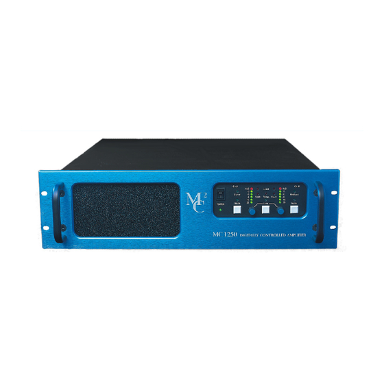
CONTENTS TECHNICAL SPECIFICATION INTRODUCTION INSTALLATION Electrical Mechanical CONNECTIONS Inputs Outputs Rear panel switches OPERATION Switching on Level controls Mute switches Link switch Level indicator Limiters Temperature control Fault indicators 2 ohm LED INTERNAL CONFIGURATION SWITCHES REMOTE CONTROL OPTION REMOTE CONTROL SET-UP INSTRUCTIONS... -
Page 3: Technical Specification
Continuous music with Crest Factor of 2.8 (9dB) 1675 1300 Continuous music with Crest Factor of 4.8 (14dB) 2200 1325 Continuous music with Crest Factor of 7.8 (18dB) 2500 1450 ** Single MC1250 orders check packing size with MC2 Audio... - Page 4 Product compliance to EC Directives This product conforms to the relevant Directives, Regulations and Standards for electronic and associated apparatus. The equipment is CE marked both on the apparatus and the packaging. A product "Declaration of Conformity" statement and information regarding auxiliary apparatus and specifications required to meet conformity is available on request from our Customer Service Department on: +44 (0) 1404 44633 This amplifier will only operate to its very high specification if it is installed and operated as...
-
Page 5: Introduction
INTRODUCTION Your MC750 digitally controlled power amplifier represents the latest technology in control circuitry coupled to a no compromise high quality class AB power amplifier. There is no dynamic switching of the audio or power rails (a very common method of achieving extra power at the expense of audio quality) thus ensuring optimum sonic performance. - Page 6 WARNING: Apparatus with CLASS I construction shall be connected to a MAINS socket outlet with a protective earthing connection. WARNING: To prevent injury, this apparatus must be securely attached to the rack in accordance with the installation instructions. Read these instructions. 14.
- Page 7 ATTENTION: Appareils de construction de CLASSE I doit être raccordé au réseau électrique via une prise de courant reliée à la terre. ATTENTION: Pour éviter toute blessure, cet appareil doit être solidement fixé à la torture, conformément aux instructions d'installation. Lisez ces instructions.
-
Page 8: Connections
INSTALLATION: MECHANICAL To ensure that this equipment performs to specification, it should be mounted in a suitable rack or enclosure as described below. Like all high power amplifiers, it should be kept away from other equipment which is sensitive to magnetic fields. Also, this amplifier may suffer a substantial reduction in performance if it is subjected to, or mounted close to equipment which radiates high R.F. -
Page 9: Operation
OUTPUTS The speaker outputs are via 4mm shrouded binding posts. They can be used with 4mm plugs or plain wires, which can be inserted in the sides of the terminals. Terminations are as follows:- Cold Black NOTE: 1. Although the "cold" output terminals are nominally at 0V, they should not be joined together, otherwise cross-talk may be introduced. -
Page 10: Switching On
It is important that the power output of your amplifier is matched to the power handling capacity of your loudspeaker. If not, damage to the loudspeaker could occur. SWITCHING ON When the amplifier is switched on, the outputs will be muted and the controller will check for any faults. It then goes through a power up routine and finally connects the speakers to the output stages and fades up the signal to the level at which the amplifier was previously set. -
Page 11: Internal Configuration Switches
The release time can be set to infinity which changes the limiter to function as an AUTOMATIC GAIN CONTROL. In this mode, if the signal goes above the threshold level, the gain of the amplifier will be reduced. This reduction will remain until the level controls are manually turned back up, or until the amplifier is switched off. - Page 12 Sw 3 (Normally ON) When OFF the LED columns will always show the signal level and will not change to show the level control position when the level controls are adjusted. Sw 4 & 5 These select the threshold level as follows:- Sw4 Sw5 Just below clipping point.
-
Page 13: Remote Control Option
REMOTE CONTROL OPTION The MC750 is internally wired for remote control, which is easily achieved by installing the appropriate interface/drive board during the manufacturing process, without any change to the amplifiers’ performance. Description The system is designed to replicate via Windows all the controls that are available on the front panel of the amplifier (except power-on/off). -
Page 14: Remote Control Set-Up Instructions
REMOTE CONTROL SET-UP INSTRUCTIONS To set up the remote control: Connecting the system to the controlling computer The RS485 adaptor is plugged into the back of the computer and the cable (which must be 2- core with a screen) runs from this adaptor to the 9-pin D connector on the back of the first amplifier in the sequence and then on, via 9-pin D connectors, to all other amplifiers in the system, thus creating the daisy chain link from one amplifier to the next.
Need help?
Do you have a question about the MC1250 and is the answer not in the manual?
Questions and answers