Table of Contents
Advertisement
Quick Links
See also:
Service Manual
Advertisement
Table of Contents

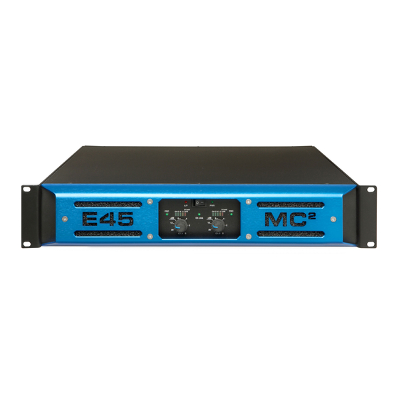
Summary of Contents for MC2 Audio E45
- Page 1 OWNER’S MANUAL (BG version) (BG version) (BG version) (BG version) AUDIO Ltd., Units 6-8, Kingsgate, Heathpark Industrial Estate, HONITON, Devon EX14 1YG England Tel: ++(0)1404.44633 Fax: ++(0)1404.44660 www.mc2-audio.co.uk...
-
Page 2: Table Of Contents
CONTENTS EC DECLARATION OF CONFORMITY IMPORTANT SAFETY INSTRUCTIONS 4, 5, 6, 7 INSTALLATION Electrical RF Emissions Mechanical GENERAL INFORMATION CONNECTIONS Inputs Outputs Bridged Operation OPERATION Switching on Level controls Bar signal indicators -3dB indicator Limiters PRC indicators Temperature control Fault indicator Bridged LED MAINTENANCE TECHNICAL SPECIFICATION... -
Page 4: Important Safety Instructions
Important Safety Instructions Read these instructions. Keep these instructions. Heed all warnings. Follow all instructions. Do not block any ventilation openings, install in accordance with the manufacturer’s instructions. Unplug this apparatus during lightning storms or when unused for long periods of time. Clean only with a dry cloth. - Page 5 DO NOT USE THE UNIT IF THE ELECTRICAL POWER CORD IS FRAYED OR BROKEN. The power supply cords should be routed so that they are not likely to be walked on or pinched by items placed upon or against them, paying particular attention to cords and plugs and the point where they exit from the appliance.
- Page 6 WARNING: Apparatus with CLASS I construction shall be connected to a MAINS socket outlet with a protective earthing connection. WARNING: To prevent injury, this apparatus must be securely attached to the rack in accordance with the installation instructions. Read these instructions. 14.
- Page 7 ATTENTION: Appareils de construction de CLASSE I doit être raccordé au réseau électrique via une prise de courant reliée à la terre. ATTENTION: Pour éviter toute blessure, cet appareil doit être solidement fixé à la torture, conformément aux instructions d'installation. Lisez ces instructions.
-
Page 8: Rf Emissions
INSTALLATION EMC (RF Emissions) The high frequency resonant converters in the E Series amplifiers have been designed to have very low radio frequency (RF) emissions, which can cause interference with other equipment. In order for this to be optimised, the amplifier should be mounted in a metal rack enclosure, which should have a separate (technical) Earth. -
Page 9: General Information
B PRC is not used and is out of circuit. Notes on Dynamic Amplifiers The E45 is the very latest example of a ‘dynamic amplifier’. This new ‘breed’ of power amplifiers provide very high peak power levels in a much smaller, and lighter, package than previously possible with conventional amplifiers. -
Page 10: Connections
Connections INPUTS The inputs are made via 3-pin XLR connectors, which are electronically balanced and should be connected via a high grade twin core screened cable, as follows:- PIN1 - Screen (see note) PIN2 - Hot (signal +) PIN3 - Cold (signal -) The amplifier is designed to operate with fully balanced equipment and ground loops or loss of performance may be experienced if connected to unbalanced sources. -
Page 11: Operation
BRIDGED (MONO) MODE Use centre Speakon connector marked ‘BRIDGED’ and connect as follows: For bridged operation: -ve (Ch A) +ve (Ch B) For 4-pole connection to both channels: Pin 1+ Ch. A +ve (Bridged switch de-selected [ie Out]) Pin 1- Ch. -
Page 12: Temperature Control
26dB gain Link 2 & 3 gives approx. 35.75dB gain = 6dBu/1.5V sensitivity E45 NOTE: Factory setting is normally link 1 & 2 = 32dB gain. Setting higher gain does not change the maximum available power but changes the level of signal input to achieve maximum power. -
Page 13: Air Filter
AIR FILTER The filter behind the air intake apertures on the front of E SERIES amplifiers should be cleaned or replaced periodically, e.g. 3-6 months. (Filters in amplifiers located in more 'dirty' atmospheres may require more frequent maintenance). Access is via the blue front panel retained by 2.5mm Hex screws. The filter should be 'dry' cleaned, using a vacuum cleaner preferably. -
Page 14: Table Of Prc Settings
Power requirements The E45 can be supplied for nominal mains voltage of 115V or 230V. An internal link can be set to either 100V or 120V for the 115V version and 220V or 240V for the 230V version. Normally these are set to 120V and 240V respectively.


Need help?
Do you have a question about the E45 and is the answer not in the manual?
Questions and answers