Advertisement
Table of Contents
- 1 Table of Contents
- 2 Tools Needed for Installation
- 3 See Exhaust Requirements
- 4 Wiring Diagram
- 5 Door Reversal
- 6 Test Mode
- 7 Reassembly
- 8 Trouble Diagnosis
- 9 Exploded View of Frame, Panel-Control
- 10 Exploded View of Front
- 11 Exploded View of Drum
- 12 Exploded View of Duct, Heater, Motor
- 13 Electrical Parts List
- Download this manual
SERVICE
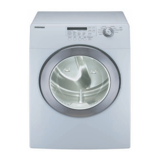
CLOTHES DRYER
CLOTHES DRYER
Model code :
DV316LGW/XAA
DV306LEW/XAA
DV316LEW/XAA
DV326LES/XAA
DV3C6BEW/XAA
DV316BEW/XAA
DV316BEC/XAA
DV306LGW/XAA
DV316LGW/XAA
DV316LGS/XAA
DV326LGS/XAA
DV3C6BGW/XAA
DV316BGW/XAA
DV316BGC/XAA
Manual
THE FEATURE OF PRODUCT
1. Super Size Capacity
2. Energy Saving
3. Time Saving
SAM0109
Advertisement
Table of Contents

Related Manuals for Samsung DV316LGW/XAA


Summary of Contents for Samsung DV316LGW/XAA
- Page 1 CLOTHES DRYER Model code : DV316LGW/XAA DV306LEW/XAA DV316LEW/XAA DV326LES/XAA DV3C6BEW/XAA DV316BEW/XAA DV316BEC/XAA DV306LGW/XAA DV316LGW/XAA DV316LGS/XAA DV326LGS/XAA DV3C6BGW/XAA DV316BGW/XAA DV316BGC/XAA SERVICE Manual CLOTHES DRYER THE FEATURE OF PRODUCT 1. Super Size Capacity 2. Energy Saving 3. Time Saving SAM0109...
-
Page 2: Table Of Contents
CONTENTS 1. PRECAUTIONS 1-1. CAUTION FOR SAFETY DURING SERVICING ................1-1 1-2. IMPORTANT SAFETY INFORMATION .....................1-2 1-3. PRECAUTIONS UPON INSTALLATION ...................1-6 2. PRODUCT SPECIFICATIONS 2-1. THE FEATURE OF PRODUCT ......................2-1 2-2. SPECIFICATIONS OF PRODUCT SPECIFICATIONS OF PRODUCT ....................2-2 2-3. OVERVIEW OF THE DRYER ......................2-3 2-4. - Page 3 CONTENTS 8. ELECTRICAL PARTS LIST ........................8-1 9. BLOCK DIAGRAM ..........................9-1 10. WIRING DIAGRAM ..........................10-1 11. PCB DIAGRAM ............................ 11-1 12. SCHEMATIC-DIAGRAMS .........................12-1 13. CIRCUIT DESCRIPTIONS ........................13-1 14. REFERENCE INFORMATION 14-1. MODEL NAME ..........................14-1 14-2. TERMINOLOGY ..........................14-2 14-3. CHECK THESE POINTS IF YOUR DRYER .................14-4 14-4.
- Page 4 1. Do not allow the customer to repair the product. The person may be injured or the product life may be shortened.. 2. Execute A/S after unplugging the power supply unit. Be careful of the electric shocks. 3. Do not plug several plugs in the same outlet. It may cause a fire due to overheat.
- Page 5 15. Do not push the control buttons with an awl,pin, or sharp materials. It may cause electric shocks and damage. 16. Check the wash machine is leveled horizontally and installed properly on the floor. The vibration may shorten the product life.. To avoid risk of fire, electric shock, serious injury, or death when using your dryer, follow these basic precau- tions: 1.
- Page 6 16. Always clean the lint filter after every load. A layer of lint in the filter reduces drying efficiency and pro longs drying time. 17. Use only fabric softeners or products to eliminate static that are appropriate for automatic dryers. 18.
- Page 7 Electrical Dryers - 240 VAC, 60 Hz, 30 Amps, 3-wire or 4-wire installations Gas Dryers To avoid risk of personal injury or death due - 120 VAC, 60 Hz, 15 Amps, 3†wire installa- to electrical shock: tions - Observe all local codes and ordinances. - Disconnect electrical power to unit About Ground Wires before servicing.
- Page 8 connection to the main power panel. -The round hole connection is not This equipment MUST be grounded. In the connected to a ground and/or the main power event of an electrical short circuit, grounding panel. reduces the risk of electric shock by providing an escape wire for the electrical current.
-
Page 9: Tools Needed For Installation
Tools needed for installation Proper installation is the owner’s responsibility. HOWEVER, SERVICE CALLS PERFORMED AS A RESULT OF POOR SET-UP, ADJUSTMENT, AND CONNECTION ARE THE RESPONSIBILITY OF THE INSTALLER. Make sure you have everything necessary for proper installation. 1. GROUNDED ELECTRICAL OUTLET is required. See Electrical Requirements. 2. - Page 10 DUCTING REQUIREMENTS • Use a 4-inch (10.2 cm) diameter rigid aluminum or rigid galvanized steel duct. • Do not use a smaller duct. • Ducts larger than 4 inches (10.2 cm) in diameter can result in increased lint accumulation. Lint accumulation should be cleaned regularly. •...
- Page 11 If new dryer is installed into an existing exhaust system you must make sure: • The exhaust system meets all local, state, and national codes. • That fl exible plastic duct is not used. • Inspect and clean all lint buildup from inside the existing duct. •...
- Page 12 MOBILE HOME INSTALLATION The installation of the dryer in mobile homes must conform to the Manufactured Home Construction and Safety Standard Title 24 CFR, Part 32-80 {formerly the Federal Standard for Mobile Home Construction and Safety, Title 24, HUD (Part 280), 1975} for the United States) or CSA Standards Z240 (for Canada). When installing a dryer in a mobile home, provisions for anchoring the dryer to the fl...
- Page 13 GAS REQUIREMENTS Use only natural or LP (liquid propane) gases. THE INSTALLATION MUST CONFORM WITH LOCAL CODES, OR IN THE ABSENCE OF LOCAL CODES, WITH THE NATIONAL FUEL GAS CODE ANSI/Z223.1, LATEST REVISION (FOR THE UNITED STATES), OR WITH THE CAN/CGA-B149 INSTALLATION CODES (FOR CANADA). Gas dryers are equipped with a burner vent for use with natural gas.
-
Page 14: Wiring Diagram
ELECTRICAL REQUIREMENTS NOTE: Wiring diagram is located on plate below the control panel. WARNING – • Improper connection of the equipment grounding conductor can result in a risk of electric shock. Check with a qualifi ed electrician or serviceman if you are in doubt as to whether your dryer is properly grounded. - Page 15 NOTE: It is not permissible to convert a dryer in Canada to 208 volts. REPLACEMENT PARTS AND ACCESSORIES If your dryer requires replacement parts or accessories, contact the dealer from whom you purchased your dryer or a SAMSUNG customer care center at 1-800-SAMSUNG (726-7864). 1-12...
- Page 16 INSTALLATION Parts and literature are packaged inside your dryer drum. To install: 1. Move your dryer to an appropriate location for installation. Consider installing the dryer and washer side-by-side, to allow access to gas, electrical, and exhaust connections. Lay two of the carton cushion-tops on the fl oor. Tip your dryer on its side so it will lay across both cushion-tops. 2.
- Page 17 3-WIRE SYSTEM CONNECTIONS 1. Loosen or remove center terminal block screw. 2. Connect neutral wire (white or center wire) of the power cord to the center, silver-colored terminal screw of the terminal block. Tighten screw. 3. Connect the other wires to outer terminal block screws. Tighten screws. 4.
- Page 18 Dryer Exhaust Tips WARNING: Plastic or non-metal fl exible duct presents a potential fi re hazard. 1. Let your dryer exhaust the air easily. 2. Use 4” diameter rigid metal duct.Tape all joints, including at the dryer. Never use lint-trapping screws. 3.
-
Page 19: Door Reversal
Door Reversal 1. Unplug power cord. 6. Place the door on the other side and reattach it to dryer. 2. Remove two door hinge screws. 3. Lift the door and remove from dryer. 4. Remove two screws on the 7. Reassemble holder lever. opposite side of door hinge. - Page 20 Concept - Super Size Capacity - Energy Saving - Time Saving Main Feature - 7.3 cu.ft. - Energy Saving(3200 Wh/Cycle) - Time Saving (Normal Course 44 min.) Sub. Feature - Fuzzy Algorithm - Easy Reversible Door - Slanted control panel...
- Page 21 Inches (cm) Inches (cm) C. Depth with A. Height 38”(96.5) 49”(124.5) door open 90° B. Width 27”(68.6) D. Depth 30.25” (77.0) 56.8kg 5300W NO HEAT 268W HEATING 5445W...
- Page 23 DV316LG Frontier Dryer Glass Transparent Glass Transparent E/G, 3 way E/G, 3 way 5300W / 22,000 BTU/hr 5300W / 22,000 BTU/hr 240V/60Hz 240V/60Hz Louder/Softer/Off Louder/Softer/Off Up/Down Up/Down 38” x 27 x 31 38” x 27 x 31...
- Page 24 MANUAL-BOOK DC68-02312A DIE-RACK DRY DC61-01522A...
- Page 25 Memo...
- Page 26 1. Digital Graphic Display The display window shows the estimated time remaining in the cycle after the Cycle Selector dial is pressed. The estimated time remaining may fl uctuate as the cycle progresses. The Drying light will illuminate and remain lit until the cycle is complete. When your dryer is in the cool-down phase, the Cooling light will illuminate.
- Page 27 5. Signal Selection Button When the cycle is complete, a chime will sound. When the Wrinkle Prevent option is selected, the chime will sound intermittently. Adjust the volume of the chime or turn it off by pressing the Signal button. Press the button repeatedly to scroll through the choices.
- Page 28 Wrinkle Default Drying Cooling prevent Cycle Temp con- Sensor dry Time Time Time Time trol level High Normal Normal dry 44 min 39 min 5 min 90 min (Medium) Heavy High (No Normal dry 60 min 55 min 5 min 90 min Duty change)
- Page 29 A function to prevent children from playing with your dryer. If you want to set or release Child Lock, press both the Time and Signal buttons at the same time for 3 seconds. How to Set: 1. It can be set while your dryer is running. 2.
- Page 30 INSTALLING THE DRYING RACK 1. Open dryer door. 2. Position drying rack in tumbler, placing the rear legs in the two recessed areas of the dryer’s back wall. 3. Place the front lip of the drying rack on top of the lint fi lter. 4.
- Page 32 − −...
- Page 34 An occurrence of an Error will make a sound of error melody for 5sec and continuously show one of the Error Displays from the following errors. Display Description Trigger Action Taken Check for: - Clogged lint screen. The Thermistor Dryer Thermistor Short - Restricted vent sys- resistance is Sensed...
-
Page 35: Test Mode
4-2. TEST MODE 4-2-1. Continuous Run Mode Continuous Run Mode: 1. Press Signal + Dryness Level for 3 sec during Power On State (Normal User Mode) . 2. Once in Continuous Run Mode, 7-Segment will toggle display “cc” and the remaining time. 3. - Page 36 4-2-3. Sensor Bar Touch Data Mode Defi nition of Sensor Bar Touch Data Mode: -While in Power On pressing Signal and Temp Keys for 3 seconds -This action will put the dryer into sensor bar touch data mode - Dryer will display Sensor Bar data. This mode is default mode of entering service mode How to Enter: - While in Power off pressing Signal and Temp Keys for 3 seconds (same for all Frontier models.) 4-2-4.
- Page 37 4-2-5. Software Version Mode Defi nition of Software Version Mode: - While in Service Mode pressing the Temp key will put the dryer into the software version mode How to Enter: - To enter Special Test Mode press Temp Key until the control beep. (same for all Frontier models.) ex) In case of “U105”, U0 means major version “v1“...
- Page 38 TOOL 10mm Heater (1) Box driver 13mm Motor (1), Balance (5), 2 holes of each left and right of the 19mm shock absorber 1 Pulley hole Replaceable for the box driver. Double-ended 10, 13,19mm Since the bolt runs idle when the box driver is used, use the spanner box driver 17mm.
- Page 39 Warning! To avoid risk of electrical shock, personal injury or death, disconnect the power to the washing machine. Descriptive Picture Part Name How To Do 1.Disconnect power supply to unit. 2.Remove 2 10mm screws from dryer back. Removal 3.Slide Top Cover towards the rear and lift from unit.
- Page 40 Part Name Descriptive Picture How To Do 1.Disconnect power supply to unit. 2.Remove Top Cover. 3.Remove Console. 4.Remove four screws attaching Front Panel to dryer. 5.Remove two screws in the door Front Panel area. Removal 6.Pull Front Panel forward and disconnect the Interior Light harness.
- Page 41 Descriptive Picture Part Name How To Do 1.Disconnect power supply to unit. 2.Remove Top Cover. 3.Remove Console. 4.Remove Front Panel. 5.Remove Console Back Cover. 6.Remove Front Bulkhead. Drum Re- 7.Remove belt from Idler Pulley. moval 8.Grasp the Drum with one hand and the belt with the other.
- Page 42 Descriptive Picture Part Name How To Do 13.Slide the Motor Blower. Assembly toward the heater and lift to disengage the tabs on the motor from the slots in the base. 14.Remove the 14mm nut securing the blower wheel to the shaft. The nut is a left hand Motor/Blow- thread.
-
Page 43: Reassembly
Reassembly procedures are in the reverse order of dissasembly procedures. -
Page 44: Trouble Diagnosis
As the micom dry machine is confi gured of the complicate structure, there might be the service call. Below information is prepared for exact trouble diagnosis and suitable repair guide. Caution for the Repair and Replacement Please follow below instruction for the trouble diagnosis and parts replacement. 1) As some electronic components are damaged by the charged static electricity from the resin part of wash machine or the human body, prepare the human body earth or remove the potential differ ence of the human body and wash machine by contacting the power supply plug when the work contact... - Page 45 Problem What To Do • All wires are hooked up to their corresponding terminals. • Dryer is plugged in. • Blown fuse or circuit breaker. • Door switch functional...door closed. Check for error code 3 (See Table for code defi nition). Will Not Start or Run •...
- Page 46 -If you plug in the power cord and turn Power S/W on, memorized data is displayed. If any data is not displayed, check the followings. No Power ON The Voltage Of Betweenⓐand ⓑIs Check The Trans As Big As 12V? The Voltage Of Check The Diode Betweenⓒand ⓓ...
- Page 47 The Value Of Measurement Result Of Between Micom 25 Check The Power Source And Gnd Is 5V? Check IC4 7533 R40 100 CE7 1UF Check The Curve Check D11,12,16,17,18 Output Of ⓐ ? Check The Micom Check TR2,R35 Number 67 ? Check The Part Of Oscillator...
- Page 48 The Value Of Measurement Result Of Between Micom 25 Check The Power Source And Gnd Is 5V? Check IC4 ⓐ Part Confirm DC12V ? Check The Part Of Power Source Exchange BUZZER1, Check R5,R46...
- Page 49 Memo...
-
Page 50: Exploded View Of Frame, Panel-Control
7. EXPLODED VIEW AND PARTS LIST 7-1. EXPLODED VIEW OF FRAME, PANEL-CONTROL Y0161 Z0050 Z0050 A0367 U0363 A0364 N0006 Y0162 Z0019 Z0050 P0001 Z0006 C0002 C0082 C0108 F0125 C0029 C0105 A0282 Z0007 M0066 C0044 A0364 P0170 Z0050 A0370 W0002 F0028 F0229 N0006 Z0007... - Page 51 DC97-07516G ASSY-FRAME DV316BEC/XAA,FRONTIER/GAS/BBY DV316BEC F0028 DC97-07516F ASSY-FRAME DV316LGS/XAA,FRONTIER/GAS DV316LGS F0028 DC97-07516E ASSY-FRAME DV316LES/XAA,FRONTIER/GAS DV316LES F0065 DC97-10912A ASSY-FRAME PLATE(U) DV316LGW/XAA,FRONTIE F0229 DC61-01233A GUIDE-EXHAUST WINGS-DRYER,SECC(EGI),T0.8 M0066 DC61-01522A DIE-RACK DRY WINGS-DRYER,TB-54,NTR,P N0006 DC61-40081A HOLDER-WIRE DAWH-2NC,NYLON66,NTR DV316LGW, DV316LEW DV3C6BEW, DV3C6BGW P0001 DC97-08634F ASSY-COVER TOP...
-
Page 52: Exploded View Of Front
7-2. EXPLODED VIEW OF FRONT Location No. Code No. DESCRIPTION SPECIFICATION QTY SA/SNA REMARK DV316BEC, DV316BGC D0010 DC97-10342B ASSY-COVER DOOR WF316BAW,SPRAY(IMPERIAL- DV316BEW, DV316BGW DV3C6BEW, DV3C6BGW D0010 DC97-10342A ASSY-COVER DOOR WF-G106AW,FRONTIER DV306LEW, DV306LGW DV316LGW, DV316LEW D0010 DC97-10338A ASSY-COVER DOOR WF326LAW,FRONTIER DV316LES, DV316LGS D0048 DC61-01222A BRACKET-HINGE... -
Page 53: Exploded View Of Drum
7-3. EXPLODED VIEW OF DRUM Location No. Code No. DESCRIPTION SPECIFICATION SA/SNA REMARK A0125 6046-000310 STAND OFF ID11.5,L2,NTR,NYLON66,DAWH-3NA DV316LGW, DV316LEW DV316BEC, DV316BGC A0371 DC97-10362A ASSY-S.DRUM FRONT DV736E4/XAA,FRONTIER-D DV316BEW, DV316BGW DV316LES, DV316LGS DV3C6BEW, DV3C6BGW A0371 DC97-10362B ASSY-S.DRUM FRONT DV306LEW/XAA,FRONTIER- DV306LEW, DV306LGW DV316LGW, DV316LEW DV316BEC, DV316BGC F0041... -
Page 54: Exploded View Of Duct, Heater, Motor
7-4. EXPLODED VIEW OF DUCT, HEATER, MOTOR Location No. Code No. DESCRIPTION SPECIFICATION REMARK F0005 DC47-00016A THERMOSTAT B-2,250V,25A20~15040~15 DV316LGW, DV3C6BGW F0005 A0376 Z0050 F0005 DC47-00017A THERMOSTAT 60T21,250V,15A/25A20~150, DV316BGC, DV316BGW A0378 Z0050 DV306LGW, DV316LGS Z0050 DV316LEW, DV3C6BEW Z0007 F0005 DC47-00018A THERMOSTAT 60T11,250V,25A20~15030~ DV316BEC, DV316BEW Z0007... - Page 55 7-5. PARTS LIST (SA) Location No. Code No. DESCRIPTION SPECIFICATION SA/SNA REMARK DV316LEW, DV3C6BEW A0368 DC61-01428A HOLDER-POWER MDE9700AYW,PP,WHT,POW DV316BEC, DV316BEW DV306LEW, DV316LES C0043 DC64-01110C BUTTON-PUSH(F) WF316BAC,ABS,SILKY CH DV316BEC, DV316BGC D0111 DC72-00032B SPONGE-EPDM MDE7800AYW,EPDM,T3,W15,L34 DV316LEW, DV3C6BEW F0005 DC47-00015A THERMOSTAT B-2,250V,25A20~15040~15 DV316BEC, DV316BEW DV306LEW, DV316LES F0089 DC63-00540A COVER-POWER...
-
Page 56: Electrical Parts List
8. ELECTRICAL PARTS LIST -You can search for updated part codes through ITSELF web site. URL : http://itself.sec.samsung.co.kr/ Loc. No. Code No. Description & Specification SA/SNA REMARK H0001 DC96-00791A ASSY-MOTOR DUCT;MDE7800AYW,240V/60HZ Z0050 6002-000231 SAREW-TAPPING;TH,+,-,2S,M4,L12,ZPC(YEL), U0095 6602-001314 BELT-TIMING GEAR;0724,RUBBER(GOODYEAR),T H0032 DC96-01112A ASSY-MOTOR;MDE9700AYW,DRYER/MOTOR... - Page 57 Loc. No. Code No. Description & Specification SA/SNA REMARK D0111 DC72-00032C SPONGE-EPDM;MDE7800AYW,EPDM,-,T5,W20,L38 R0015 DC97-08300A ASSY-DRUM BACK;MDG7800AWW,GAS/PREMIUM/ST Z0007 6002-000239 SAREW-TAPPING;TH,+,-,2S,M4,L8,ZPC(YEL),S Z0004 DC60-50145A NUT-HEX;-,MSWR10,-,-,-,-,-,-,M10 H0074 DC60-60060A WASHER;-,T2,-,ID12,OD24,-,YEL,- R0170 DC61-01237A BRACKET-DRUM BACK;WINGS-DRYER,SECC(EGI), R0170 DC61-01238A BRACKET-DRUM BACK;WINGS-DRYER,SECC(EGI), H0081 DC97-07523A ASSY-ROLLER;MDE7800AYW,DRYER/EPDM 6601-001291 BEARING-OILLESS;-,ID13,OD21.8,L22,FE+OIL R0164 DC61-01227A GUIDE-ROLLER;WINGS-DRYER,PP,-,-,-,BLU,- R0165 DC61-01228A...
- Page 58 Loc. No. Code No. Description & Specification SA/SNA REMARK F0117 6041-001035 RIVET-RH;K1661-0512,AL(A5052),OD3.9,L11 DC61-01236A BRACKET-DRUM FRONT;WINGS-DRYER,SECC(EGI) R0002 DC66-00435A DRUM-FRONT;DV736E4/XAA,SECC(EGI),T1.0,-, R0172 DC97-10355A ASSY-DRUM WRAPPER;DV736E4/XAA,FRONTIER(G Z0041 6002-001204 SAREW-TAPPING;TH,+,-,1,M4,L16,PASS,STS43 DC02-00014A CHEMICALS-BOND;MDE7800AYW,-,-,-,ASSY-FEL A0356 DC63-00597C SHEET-DAMPING;MDE9700AYW,BUTYL,T1.5,W100 R0003 DC66-00397A DRUM-WRAPPER;WINGS-DRYER,STS-304,T0.6,-, R0006 DC66-00436A DRUM-LIFTER;DV736E4/XAA,TI-42,-,-,-,GRY, F0024 DC97-07618A ASSY-GASKET PAD;MDE7800AYW,DRYER/DRUM-WR A0001 DC97-10370A ASSY-CASE;DV736E4/XAA,FRONTIER-DRYER...
- Page 59 Loc. No. Code No. Description & Specification SA/SNA REMARK W0037 DC96-00763A ASSY-FLAT WIRE HARNESS;GR-PJT,FLAT WIRE W0004 DC96-00765A ASSY-M.WIRE HARNESS;GR-PJT,GAS USA P0001 DC97-08634A ASSY-COVER TOP;GW-PJT,- P0053 DC63-00523A COVER-TOP;GW-PJT,SECC(EGI),T1.0,W684,L56 W0059 DC63-10002Q SPONGE-HARNESS;KS-PJT,PU-FOAM,-,T3,W100, F0037 DC97-10357A ASSY-FRONT;DV736E4/XAA,FRONTIER-DRYER Z0027 6001-001773 SAREW-MACHINE;TH,+,-,M5,L12,PASS,STS430, Z0008 6002-000444 SAREW-TAPPING;TH,+,-,2S,M4,L14,PASS,STS4 Z0020 6006-001174 SAREW-TAPPING;WE,TH,+,M4,L12,ZPC(YEL) F0064...
- Page 60 GUIDE-LED(C);WF-G106AW,HIPS,-,-,-,NTR,FR DE02-00036A CHEMICALS-FLUX SOLDER;KS-77S,-,-,-,-,KOK DE02-00060A CHEMICALS-ALCOHOL;ALL,MODEL,-,-,-,-,-,- DE02-00083A SOLDER-WIRE;S63S,D3.0,-,-,-,-,-,-,- DE02-00086A SOLDER-WIRE FLUX;RS60S,-,D1.2,60SN/40PB, Y0052 DE13-20017A IC-DRIVE;KID65003AP,DIP,16P,STICK,TR-AR DE39-60001A WIRE-SO COPPER;,PI0.6,SN,T,52MM TAPING_W DC97-10875A ASSY-HOLDER PCB;DV316LGW/XAA,FRONTIER/PC A0367 DC61-01229A HOLDER-PCB;WINGS-DRYER,SECC(EGI),T0.8,-, Y0161 MFS-FTDT-00 ASSY PCB PARTS(M);MFS-FTDT-00 0103-002581 RESIN-PUR;CPU-55B/UEP 700FB,-,-,94V0 94.7 0103-002582 RESIN-PUR;UEP 700FA/CPU-55A,-,-,94V0 47.3 0401-000005 DIODE-SWITCHING;1N4148,75V,150mA,DO-35,T 0402-000137 DIODE-RECTIFIER;1N4007,1KV,1A,DO-41,TP...
- Page 61 Loc. No. Code No. Description & Specification SA/SNA REMARK Y0053 1103-001203 IC-EEPROM;524C20D21,256x8,DIP,8P,9.6x6.4 1202-000001 IC-VOLTAGE COMP.;7533,TO-92,3P,-,SINGLE, 1405-001129 VARISTOR;460VDC,7500A,22.5X10.1MM,BK 2001-000034 R-CARBON;220OHM,5%,1/4W,AA,TP,2.4X6.4MM 2001-000042 R-CARBON;1KOHM,5%,1/4W,AA,TP,2.4X6.4MM 2001-000047 R-CARBON;2.2KOHM,5%,1/4W,AA,TP,2.4X6.4M 2001-000052 R-CARBON(S);3.3KOHM,5%,1/2W,AA,TP,2.4X6. 2001-000073 R-CARBON;33Kohm,5%,1/4W,AA,TP,2.4x6.4mm 2001-000281 R-CARBON;100OHM,5%,1/8W,AA,TP,1.8X3.2MM 2001-000290 R-CARBON;10KOHM,5%,1/8W,AA,TP,1.8X3.2MM 2001-000429 R-CARBON;1KOHM,5%,1/8W,AA,TP,1.8X3.2MM 2001-000432 R-CARBON;1MOHM,5%,1/4W,AA,TP,2.4X6.4MM 2001-000577 R-CARBON;2KOHM,5%,1/8W,AA,TP,1.8X3.2MM 2001-000734 R-CARBON;4.7KOHM,5%,1/8W,AA,TP,1.8X3.2M 2001-001113 R-CARBON(S);270KOHM,5%,1/2W,AA,TP,2.4X6.
- Page 62 IC-DRIVE;KID65003AP,DIP,16P,STICK,TR-AR Y0040 DE29-90002A FILTER-EMI BEAD;S,80/100MHZ-MIN65,T,BFS3 Y0010 DE30-20016A BUZZER;CBE2220BA,STICK,-,-,-,-,-,-,- Z0007 6002-000239 SAREW-TAPPING;TH,+,-,2S,M4,L8,ZPC(YEL),S U0363 6502-000127 CABLE CLAMP;DAWH-18NB,ID15,-,NYLON66,NTR A0364 DC61-60074A CLAMPER-WIRE SADDLE;-,NYLON#66(DAWS-6NB) F0001 DC97-10871A ASSY-FRAME CASE;DV316LGW/XAA,FRONTIER-DR Z0050 6002-000231 SAREW-TAPPING;TH,+,-,2S,M4,L12,ZPC(YEL), Z0007 6002-000239 SAREW-TAPPING;TH,+,-,2S,M4,L8,ZPC(YEL),S Z0062 6002-001384 SAREW-TAPPING;TH,+,WT,C-TITE,M4,L10,ZPC( Z0019 6006-001170 SAREW-TAPPING;TH,+,WT,TC,M4,L10,ZPC(YEL) Z0020 6006-001174 SAREW-TAPPING;WE,TH,+,M4,L12,ZPC(YEL) 6009-001317 SAREW-SPECIAL;CH,+,-,M4,L10,ZPC(YEL),SWR...
- Page 63 Loc. No. Code No. Description & Specification SA/SNA REMARK B0075 DC61-01226A BRACKET-LEG;WINGS-DRYER,SECC(EGI),T1.6,- F0028 DC97-07516B ASSY-FRAME;MDG9700AWW,MAYTAG/PREMIUM/GAS F0094 DC61-01199B FRAME;WINGS-PROJECT,PCM,-,-,WHT,T0.8 Y0159 DC61-01314A PLATE-STEEL;MDE7800AYW,PCM(GI),T0.8,W961 X0014 DC61-01225A PLATE-BOTTOM;WINGS-DRYER,SECC(EGI),T1.0, A0113 DC63-00621A SHEET-INSULATION;MDE9700AYW,FELT,T5,W200 F0117 6041-001035 RIVET-RH;K1661-0512,AL(A5052),OD3.9,L11 A0370 DC97-07519A ASSY-DUCT EXHAUST;MDE7800AYW,DRYER DC61-01234A BRACKET-EXHAUST;WINGS-DRYER,AL-COAT,T0.8 DC67-00131A DUCT-EXHAUST;WINGS-DRYER,SGCC(GI),T0.4,- D0111 DC72-00032D SPONGE-EPDM;MDE7800AYW,EPDM,-,T3,W15,L32 F0117 6041-001030...
- Page 65 Memo...
- Page 66 10-1...
- Page 67 Memo 10-2...
- Page 68 11-1...
- Page 69 11-2...
- Page 70 12. SCHEMATIC DIAGRAMS * This Document can not be used without Samsung’s authorization. 12-1...
- Page 71 * This Document can not be used without Samsung’s authorization. 12-2...
- Page 72 13-1...
- Page 73 ▶ Function Generates a required DC power of 12V or 5V in case of supplied or disconnected AC power. ▶ Description - When AC 220V is applied to CN3, D17 D20 transforms it to DC 300V. - DC 300V is generated for the LVT1 secondary source by IC3 and PC1 turning on/off.
- Page 74 ▶ Function Controls each driving system (VALVE, DOOR S/W, DRAIN-MOTOR) by turning RELAY or TRIAC on/off. ▶ Description - MICOM outputs a high signal of 5V from pin # 1 - 7 of IC7 and IC9. - Then, pin # 10 to 16 of IC7 and IC9 are electrically grounded (0V). - When pin # 10 to 16 are grounded, this creates an electric potential difference from the 12V that turns on RELAY 5,6,7 and TRIAC2,3,4,5.
- Page 75 ▶ Function Supplies power to the motor and turns it CW/CCW (Right / Reverse direction). ▶ Description - The operation of TRIAC1 is the same as that of the driving system. - If the electric potential of R48 is grounded (0V), TRIAC1 turns on. - CN1 detects if the door is locked or unlocked.
- Page 76 ▶ Function Detects signals from the sensor and controls the current system. ▶ Description - The water level sensor is connected to pin 4 of CN7. - The frequency of the level sensor changes according to the water amount in the tub. - Then, the frequency is input to MICOM pin 48 for detecting the water amount.
- Page 77 ▶ Function Detects the current RPM of the motor and controls the output. ▶ Description - The motor TACHO sensor is connected to CN10 B-pin. - According to the current RPM of the motor, a square wave is applied to pin 8. - The square wave that is input to TR2 BASE turns the motor on if high (5V), and turns it off if low (0V).
- Page 78 ▶ Function Applies the electric current to the silver plate during the water supply and uses the silver water to perform the bacteria-free or sterilization processes. ▶ Description - Selects the silver nano feature to operate the system. - Supplies water to the two silver plates AG_B and AG_A. Then, SINAL_A and SIGNAL_B output a high signal of 5V.
- Page 79 Memo 13-8...
- Page 80 14-1...
- Page 81 ASSY-MAIN PCB (Imbalance Sensor) → To prevent the laundry from gathering on one side of the tube causing noise and vibration, the washing machine uses an imbalance detection device that evenly disentangles the laundry before the hydrating cycle starts. DOOR-LOCK S/W →...
- Page 82 → The machine does a preliminary wash of about 10 minutes prior to the main wash. This is particularly effective for cleaning badly stained laundry. → The tube automatically rotates when no water is supplied to detect the laundry weight so that the proper wash time can be determined.
- Page 83 • Be sure the door is latched shut. • Be sure the power cord is plugged into a live electrical outlet. doesn’t run. • Check the home’s circuit breaker and fuses. • Press the Cycle Selector dial again if the door is opened during the cycle. •...
-
Page 84: Information Codes
Call for service. See below. Be sure the door is latched shut. Door open error If problem When the door is open, the dryer continues, call for service. See will not operate. below. - For any codes not listed above, call 1-800-726-7864 (1-800-SAMSUNG). 14-5... - Page 85 The following symbols provide garment care directions without words. The care label will include, in order, four symbols: washing, bleaching, drying, and ironing (or dry cleaning when necessary). The use of symbols ensures consistency among garment manufacturers of domestic and imported items. Follow care label directions to maximize garment life and reduce laundering problems.
- Page 86 Samsung Electronics Co.,Ltd. -This Service Manual is a property of Samsung 416, Maetan-3Dong, Yeongtong-Gu, Suwon City, Electronics Co., Ltd. Gyeonggi-Do, Korea, 443-742 Any unauthorized use of Manual can be punished Printed in Korea under applicable International and/or domestic P/N : DC68-02632A-00 law.
Need help?
Do you have a question about the DV316LGW/XAA and is the answer not in the manual?
Questions and answers