Panasonic EP1285 Service Manual
Hide thumbs
Also See for EP1285:
- Operating instructions manual (20 pages) ,
- Instrucciones de uso (20 pages) ,
- Operating instructions manual (21 pages)

Related Manuals for Panasonic EP1285


Summary of Contents for Panasonic EP1285
-
Page 1: Specifications
EP1285 ORDER NO.0808U08C1 MASSAGE LOUNGER EP1285 SPECIFICATIONS ©2008 Matsushita Electric Works, Ltd. All rights reserved. Unauthorized copying and distribution is a violation of law. - 1 -... -
Page 2: Table Of Contents
EP1285 ORDER NO.0808U08C1 CONTENTS Page 1 COMPONENTS IDENTIFICATION…………………………………………………………………………………………………………………………3 2 TURNING ON THE POWER………………………………………………………………………………………………………………………………5 3 REQUIRED TOOLS…………………………………………………………………………………………………………………………………………6 4 DISPLAY METHOD OF MASSARG BLOCK TOTAL USE TIME AND OPERATION TIME…………………………………………………………7 5 DISASSEMBLY………………………………………………………………………………………………………………………………………………10 6 CHECKING AFTER REPAIR……………………………………………………………………………………………………………………………41 7 CHECKING…………………………………………………………………………………………………………………………………………………42 8 CHECING THE AIR BAG PRESSURE……………………………………………………………………………………………………………………46 9 EXPLODED VIEW…………………………………………………………………………………………………………………………………………48... -
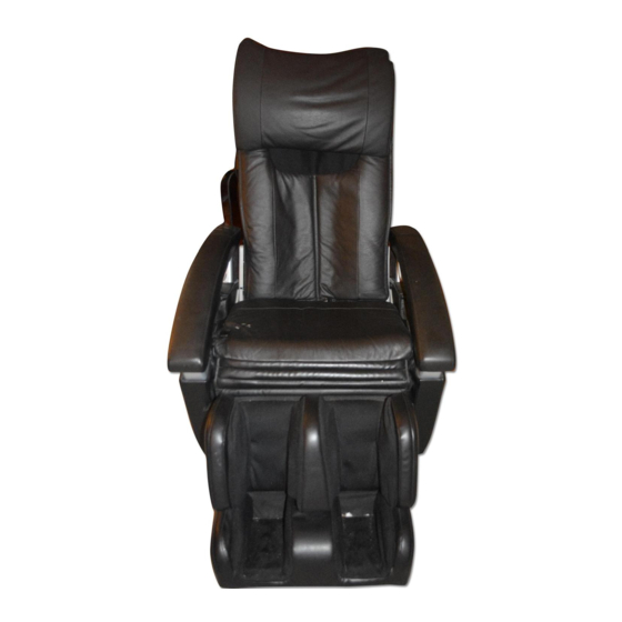
Page 3: Components Identification
EP1285 ORDER NO.0808U08C1 1. COMPONENTS IDENTIFICATION 1.1. MASSAGE LOUNGER - 3 -... - Page 4 EP1285 ORDER NO.0808U08C1 1.2. CONTROLLER - 4 -...
-
Page 5: Turning On The Power
EP1285 ORDER NO.0808U08C1 2. TURNING ON THE POWER Plug the power plug into the power socket. Turn the lock switch to the open position. Turn on the power switch on the back of the unit. ・ When the operating lock switch is pointing toward ‘lock’, the power switch cannot be moved to the ‘on’ position. -
Page 6: Required Tools
EP1285 ORDER NO.0808U08C1 3. REQUIRED TOOLS - 6 -... - Page 7 EP1285 ORDER NO.0808U08C1 DISPLAY METHOD OF MASSAGE BLOCK TOTAL USE TIME AND OPERATION TIME 4.1. Total use time 1. Close the Cover of the Controller. 2. While pushing the Up/down buttons of neck roller position, turn on the Switch of the Power source switch block. Keep pushing the Buttons more than approximately three seconds.(OFF/ON button lights.)
- Page 8 EP1285 ORDER NO.0808U08C1 4.2. Display method of operation time While in the display method of Massage block total use time, push the buttons on the Controller to indicate the accumulative usage time of each operations. * Open the Cover of the Controller.
- Page 9 EP1285 ORDER NO.0808U08C1 How to fold the Massage chair ① Turn off the switch. ② Lock it. ③ Pull off the Plug from the power source and also from the Power source switch box. Remove Rear cushion and the Headrest from the Massage chair.
-
Page 10: Disassembly
EP1285 ORDER NO.0808U08C1 5 DISASSEMBLY 5.1. Disassembly of Headrest, Back cushion, and Armrests 1. Unzip the Zippers, and remove the Headrest and the Back cushion. 2. Peel off the Velcro to remove the Controller cord from the Armrest. 3.Peel off the Velcro, pull out the tip of the Zippers, and unzip them. - Page 11 EP1285 ORDER NO.0808U08C1 4. Turn the cloth of the Armrest cover, and unscrew four Screws (two each on left and right). 5.Lift the Armrest to remove. Caution in installing Install the hook of the Armrest to the recess of the Armrest bottom.
- Page 12 EP1285 ORDER NO.0808U08C1 6. Unhook two hooks of the back and front using the Slotted screwdriver and remove the A. 7. Open the hook by hand and remove the B. Caution in installing Be sure not to make the cloth outside when installing the B.
- Page 13 EP1285 ORDER NO.0808U08C1 8. Pushing the Seat cushion, remove two Push-turn rivets. 9. Turn the cloth, and remove other four Push-turn rivets. 10. Remove the Push-turn rivet installing the C, and unscrew the Screw from the reverse side. - 13 -...
- Page 14 EP1285 ORDER NO.0808U08C1 11. Unscrew two Screws and remove the D. 12. Unscrew the Screw and remove the E. 13. Unscrew three Screws and remove the F. 14. Remove the other side similarly. 5.2. Removing the Seat 1. Execute all the 5.1. Removing the Headrest, Back cushion, and Armrests.
- Page 15 EP1285 ORDER NO.0808U08C1 3.Cut the Cable tie and unzip the Zippers.. 4. Unhook the Hook using the Slotted screwdriver, etc. 5. Lift the Seat, remove four Push-turn rivets, and remove the Seat. Caution in installing Be careful of the directions of cloth when installing it.
- Page 16 EP1285 ORDER NO.0808U08C1 6. Remove three Push-turn rivets. 7. Remove four Push-turn rivets and remove the H. 5.3. Removing the Ottoman 1. Execute all the procedures of 5.1. Removing the Headrest, Back cushion, and Armrests. 2. Execute the procedure of 5.2. Removing the Seat.
- Page 17 EP1285 ORDER NO.0808U08C1 4. Remove the Snap pin, which fixes the Ottoman lift unit. 5. You can remove the Ottoman after removing the right/left Hinge pin Bs, Washers, and U nuts. - 17 -...
- Page 18 EP1285 ORDER NO.0808U08C1 5.4. Removing the Ottoman 1. Execute all the procedures of 5.3. Removing the Ottoman. 2. Unscrew two screws and remove the K. 3. Unzip two Zippers. 4. Pull out the Hoses from the hole of the Cloth, remove a Spring and a Hose, and you can remove the Air Ottoman cloth.
- Page 19 EP1285 ORDER NO.0808U08C1 5. Pull off the Snap pin, and remove the Pins (one each on right/left), then the Ottoman block can be separated into top and bottom. 6. Remove the Air bags as the figure. - 19 -...
- Page 20 EP1285 ORDER NO.0808U08C1 7. Remove the Air bags as the figure. Caution in installing Align the Hoses as the figure and bundle them. Caution in installing Be careful of the directions of the Sole shiatsu sheets. - 20 -...
- Page 21 EP1285 ORDER NO.0808U08C1 5.5. How to align the Ottoman hoses 1. Hold the Hoses as the figure. Be careful not to hold them wrongly. 2. Turn the Hoses over once at your side. 3. Turn the Hoses anticlockwise 180°. - 21 -...
- Page 22 EP1285 ORDER NO.0808U08C1 4. Connect the Hoses to the I-shaped 3-row joint on the Under box. 5. With the Ottoman extended fully, hook the Hoses to the Seat front pipe with the Cord clip. Be careful that Hoses are not bent.
- Page 23 EP1285 ORDER NO.0808U08C1 5.6. Removing the Massage mechanism block 1. Unscrew three Screws, and remove the I. 2. Pull out the tips of Zippers from the bottom, cut the Cable ties, and unzip the Zippers pulling them upward. - 23 -...
- Page 24 EP1285 ORDER NO.0808U08C1 3. Turn over the Cloth, unscrew four Screws, and remove the Rear cover. Caution in installing Be sure not to make the Ribs outside the Rear cover when installing the Rear cover. 4. Unscrew three Screws each from right/left, and remove Rail piece sets.
- Page 25 EP1285 ORDER NO.0808U08C1 5. Unscrew the Screws, pull off the Cable tie, disconnect the Connector, and remove the Cover clip. 6. Turn the Up/down sensor plate anticlockwise and lift the Massage mechanism block to remove it. (approx. six rounds) 7. Unhook the Hook of the Center cloth, and remove the Massage mechanism block.
- Page 26 EP1285 ORDER NO.0808U08C1 5.7. Installing the Massage mechanism block 1. Remove the Center cloth, and pass it through the hole of the Massage mechanism block. 2. Move the Massage mechanism block downward rotating the Up/down sensor board clockwise till the teeth join.
- Page 27 EP1285 ORDER NO.0808U08C1 4. Connect the Connectors. 5. Push the buttons of Massage and Downward on the Controller and move the Massage mechanism block to the middle. 6. Install the Center hook, first bottom and then top. 7. Move the Massage mechanism block to the lowest position till it stops pushing the Position button on the Controller.
- Page 28 EP1285 ORDER NO.0808U08C1 8. Adjust the length from the bottom to approx. 0.4 in. (10mm). If the Massage mechanism block is too high, turn the Up/down sensor gear clockwise to adjust. If the Massage mechanism block is too low, turn the Up/down sensor gear counterclockwise to adjust.
- Page 29 EP1285 ORDER NO.0808U08C1 4. Unscrew two Screws. 5. Remove the Nuts at both sides and remove the Rear frame. Caution in installing The work would be easier when you assemble the Rear frame if you pass the Cord through the hole of the Massage wheel cover.
- Page 30 EP1285 ORDER NO.0808U08C1 5.9. Removing the Sub PCB 1. Execute all the procedures of 5.1. Removing the Headrest, Back cushion, and Armrests. 2. Unscrew four Screws (two each at right/left) and remove the Under box top. 3. Unscrew two Screws, and remove the Under box top right and the Under box top left, then you can pull out the Under box about half.
- Page 31 EP1285 ORDER NO.0808U08C1 Caution in disconnecting Connectors When disconnecting Connectors, hold the Connectors as the figure. 5.10. Removing the Ottoman lift unit 1. Proceed the procedures of 5.1. Removing the Head rest, Back rest cushion, Arm rest and 5.8. Removing the Under box.
- Page 32 EP1285 ORDER NO.0808U08C1 5.11. Removing the Reclining lift unit 1. Proceed the procedures of 5.1. Removing the Head rest, Back rest cushion, Arm rest and 5.8. Removing the Under box. 2. Take off two Connectors as the figure. 3. Take off the Hinge pin and the Snap pin , and take off the Lift unit.
- Page 33 EP1285 ORDER NO.0808U08C1 5.12. Removing the Massage mechanism block 1. Remove the Spring at A. Turn the both sides of the Tapping shaft counterclockwise using Wrenches. After a Bolt with washer is removed, insert the bar to the hole of the B and turn the other side by a Wrench.
- Page 34 EP1285 ORDER NO.0808U08C1 2. Remove the Tapping belt and the Pulley. Caution in installing Arm right * When installing the Arm right to the Massage shaft, do not insert the Position pin to the V-shaped groove. * Be careful of the directions of the Washer when installing.
- Page 35 EP1285 ORDER NO.0808U08C1 3. Unscrew two Screws on the Sensor plate, and each Screw on each Sensors. 4. Unscrew three Screws and remove the Tapping motor. - 35 -...
- Page 36 EP1285 ORDER NO.0808U08C1 5. Unscrew three Screws and remove the Up/down sensor block. Unscrew one Screw on the Up/down sensor block and remove the Up/down sensor. 6. Unscrew two A screws and remove the Connection PCB. Unscrew two B screws and remove the Connection PCB plate.
- Page 37 EP1285 ORDER NO.0808U08C1 8. Unscrew four Screws and remove the Massage gear block. 9. Unscrew six Screws (three each at both sides of B) on the Tapping shaft holder, and unscrew four Screws on the Massage gear block of A.
- Page 38 EP1285 ORDER NO.0808U08C1 10. Unscrew four Screws and remove the Massage gear block. 11. Unscrew three Screws. 12. Unscrew one Screw, and remove the Up/down rotation sensor. - 38 -...
- Page 39 EP1285 ORDER NO.0808U08C1 13. Unscrew four Screws, and remove the Up/down motor. 14. Unscrew three Screws each on both sides of Rail piece sets. * When removing the Massage mechanism block frame, hold the right Rail piece set so that the Spring does not pop out.
- Page 40 EP1285 ORDER NO.0808U08C1 16. You can execute the work from 1 to 12 even with the Massage mechanism block installed. However, the work would be easier if the Massage mechanism block is removed. 5.13. Allocation of Lead wires of Massage mechanism block...
-
Page 41: Checking After Repair
EP1285 ORDER NO.0808U08C1 6 CHECKING AFTER REPAIR - Check all the operations by the Controller. - Check if the Massage mechanism block moves with the load. - Keep the distance of more than 40cm from the Rear cover to the wall with the Back rest standing at maximum when you repair or install the Massage mechanism block. -
Page 42: Checking
EP1285 ORDER NO.0808U08C1 7. CHECKING 7.1. Checking the Controller and the Massage mechanism block Massage block stops instantly if any abnormal phenomena like motor locking happen at the test mode, however the Controller test mode continues. Controller test mode 1. Start the Massage mechanism block test mode and make all the LEDs of the Controller light, and check if the P sound is heard twice. - Page 43 EP1285 ORDER NO.0808U08C1 - 43 -...
- Page 44 EP1285 ORDER NO.0808U08C1 - 44 -...
- Page 45 EP1285 ORDER NO.0808U08C1 - 45 -...
-
Page 46: Checing The Air Bag Pressure
EP1285 ORDER NO.0808U08C1 CHECING THE AIR BAG PRESSURE 1. Cut the Cable tie and remove the Hose plug. 2. Insert the Hose of the Pressure gauge to the T-shaped joint. 3. Connect Hoses as the figure. - 46 -... - Page 47 EP1285 ORDER NO.0808U08C1 4. Push the Off/on button and the Leg massage buttons, and gauge the maximum values in two minutes. 5. Gauge the pressures in three strengths. Air gags or pump are normal if the values are in the following ranges.
-
Page 48: Exploded View
EP1285 ORDER NO.0808U08C1 EXPLODED VIEW - 48 -... - Page 49 EP1285 ORDER NO.0808U08C1 - 49 -...
- Page 50 EP1285 ORDER NO.0808U08C1 - 50 -...
- Page 51 EP1285 ORDER NO.0808U08C1 - 51 -...
- Page 52 10 REPLACEMENT PARTS LIST Ref.No. Part No. Part Name & Description Remarks Per Unit WEP1273L0088 REAR FRAME WEP1273L0698 RAIL PIECE SET WEP1273L6118 SCREW WEP1273L0628 REAR COVER FIXING PLATE WEP1272L6218 SCREW WEP1273L0688 CORD WIRE WEP1273L6318 BOLT ...
- Page 53 10 REPLACEMENT PARTS LIST Ref.No. Part No. Part Name & Description Remarks Per Unit WEP1280L0257 SLIDE BASE WEP3530L0227 PIPE END WEP3530L9667 SCREW WEP3530L0927 HINGE PIN B WEP3530L6937 V LOCK NUT WEP3530L0187 MULTI ACTION SPRING ...
-
Page 54: Replacement Parts List
10 REPLACEMENT PARTS LIST Ref.No. Part No. Part Name & Description Remarks Per Unit WEP1082T3678 HEADREST T WEP1082K3618 BACK CUSHION BLACK WEP1082T3618 BACK CUSHION T WEP1082K3148 MASSAGE WHEEL COVER, BLACK WEP1082T3148 MASSAGE WHEEL COVER T ... - Page 55 10 REPLACEMENT PARTS LIST Ref.No. Part No. Part Name & Description Remarks Per Unit WEP1273L2128 UP/DOWN ROTATION SENSOR INSTALL PLATE WEP1273L2118 UP/DOWN SENSOR WEP1273L4638 UP/DOWM SENSOR GEAR WEP1273L6048 UP/DOWN STOPPER SPRING WEP1273L6038 SCREW WEP1273L4058 UP/DOWN DRIVING BLOCK ...
Need help?
Do you have a question about the EP1285 and is the answer not in the manual?
Questions and answers
I looking for horizontal movm belt for mod EP1260