Table of Contents
Advertisement
SPECIFICATIONS
Power source
Power consumption
Kneading speed
Tapping speed
Rolling massage speed
Massaging width
Back rolling width/tapping width
Massage heads up/down travel
Regional back rolling
Shoulder position adjustment
Automatic shut-off
Dimensions (H x W x D)
Reclining angle
Weight
Accessories
: 120V AC, 60Hz
: 120W
: Approx. 28 times/min.
: Approx. 500 times/min.(per side)
: Approx. 1 cycle every 37 sec.
: Shoulder/lower back section : Approx. 2-15/16 in. (75mm)
: Narrow : Approx. 3-5/16 in. (85mm)
: Wide : Approx. 4-5/16 in. (110mm)
: Approx. 23-1/16 in. (600mm)
: Automatic repetition within approx. 4-12/16 in. (120mm) range
: 5 steps
: Approx. 15 min.
: !Not reclined and leg rest retracted : 41-11/32X34-41/64X40-35/64 in.(1050X880X1030mm)
!Reclined and leg rest extended : 29-9/64X34-41/64X68-7/64 in.(740X880X1730mm)
: Approx. 123° to 160°
: 102 lbs. (46kg)
: Back cushion, Headrest, Cushion pad
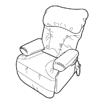
MASSAGE LOUNGER
EP1022-U1
© 2001 Matsushita Electric Works, Ltd. All rights
reserved. Unauthorized copying and distribution is a
violation of law.
ORDER NO.HPD0104U00C1
Advertisement
Table of Contents

Related Manuals for Panasonic EP1022-U1


Summary of Contents for Panasonic EP1022-U1
-
Page 1: Specifications
ORDER NO.HPD0104U00C1 MASSAGE LOUNGER EP1022-U1 SPECIFICATIONS Power source : 120V AC, 60Hz Power consumption : 120W Kneading speed : Approx. 28 times/min. Tapping speed : Approx. 500 times/min.(per side) Rolling massage speed : Approx. 1 cycle every 37 sec. Massaging width : Shoulder/lower back section : Approx. -
Page 2: Table Of Contents
14 Other 7 Motion of the clutch and belt based on various massager 15 Trouble shooting operations. 16 Exploded view 8 Massager up/down detection gear adjustment method 17 Replacement parts list for EP1022-U1 9 Removing the massage block... -
Page 3: Components Identification
EP1022-U1 1 Components identification 1.1. Massage lounger... - Page 4 EP1022-U1 1.2. Controller...
-
Page 5: Massage Range (Movement Range Of Massage Wheels)
EP1022-U1 2 Massage range (movement range of massage wheels) 2.1. Upward massage, Downward massage, Kneading rolling, Regional kneading rolling Width cannot be adjusted Neck to waist : width 75mm (minimum) Intensity adjustment Upward and downward massage (from gentle to strong) :45mm-wide adjustability where massage heads push out toward body as intensity increases.Others (from gentle to... -
Page 6: Turning On The Power
EP1022-U1 3 Turning on the power 3.1. Turning on the power Timer When the Start/reset button is pushed, a timer begins to prevent overuse. After approximately 15 minutes, time expires and the massage wheel goes into strage position. -
Page 7: Required Tools
EP1022-U1 4 Required tools... -
Page 8: Actual Wiring Diagram
EP1022-U1 5 Actual wiring diagram... -
Page 9: Display Method Of Massage Block Total Use Time And Operation Time
EP1022-U1 6 Display method of massage block total use time and operation time Total use time While pushing the whole back, neck shoulder and lower back mode programmed operation buttons simultaneiously, turn on the power switch and continue to hold the buttons for approximately 5 seconds. Release after the Start/reset LED lights up. -
Page 10: Motion Of The Clutch And Belt Based On Various Massager Operations
EP1022-U1 7 Motion of the clutch and belt based on various massager operations. Massager operation and belt motion Massager operation and clutch motion... - Page 11 EP1022-U1...
-
Page 12: Massager Up/Down Detection Gear Adjustment Method
EP1022-U1 8 Massager up/down detection gear adjustment method When the massager is removed from the chair, the position of the up/down detection gear changes, resulting in a change of the up/down stop position. When installing the massager on the back frame, be sure to adjust the position with the up/down detection gear. -
Page 13: Removing The Massage Block
EP1022-U1 9 Removing the massage block 9.1. Removing the rear cover 1. Unzip the back cushion zipper and remove the back cushion. 2. Unzip the rear cover fastener from the bottom of left side. 3. Pull the chair down backward and cut insulated ties and... - Page 14 EP1022-U1 9.2. Removing the massager 1. Remove the two installation screws from the massager cover, and take off the cover and remove the Cover clip. *Cover clip is available to remove only after taking off the cover. 2. Remove the snap pin connecting Pneumatic spring to Back frame, and push down the seatback to the front part for easy repaire.
- Page 15 EP1022-U1...
- Page 16 EP1022-U1...
-
Page 17: Disassembly (Massager) And Assembly
EP1022-U1 10 Disassembly (massager) and assembly The disassembly steps 10.1 to 10.3 can be done without removing the massager from the chair (please work with the connector cord removed). 10.1. Removing the motor 1. Remove the cable tie (medium), and remove the motor lead wire connector(white). - Page 18 EP1022-U1 10.2. Removing the tapping shaft assembly 1. Cut all the insulated ties bundling each sensor and lead wires with the aid of a nipper, and remove the lead wires bundled to the wire saddles (medium, large). 2. Remove all the connectors to the main circuit board.
- Page 19 EP1022-U1...
- Page 20 EP1022-U1...
- Page 21 EP1022-U1 10.3. Removing the gear box 1. Perform removal of steps 1 to 11 of " 10.2. Removing the tapping shaft assembly ". 2. Remove one screw and the Capacitor. 3. Remove the transformer set screw, and remove the transformer and remove the base for transformer set screw R to T and remove the base for transformer.
- Page 22 EP1022-U1 10.4. Removing the massage wheel unit set (right, left) (Remove the massager from the chair before beginning the following procedure.) 1. Perform steps 1 to 11 in section, "10.2 Removing the tapping shaft assembly". 2. Remove screws a and b which connect the gear box and main frame, and remove the main frame. (When removing the main frame, turn the massage clutch hex nut so that the massage width is at its minimum.)
- Page 23 EP1022-U1...
- Page 24 EP1022-U1 10.5. Removing and mounting the up/down shaft bolt *1. To remove the up/down shaft bolt, the box driver (Ø13 mm) must be used. To install, the torque wrench with Ø13 mm must be used. *2. The torque wrench with Ø13 mm socket and the box driver (Ø13 mm) are available as parts.
-
Page 25: Cord Arrangement Of The Connecting Cord For Power Supply And The Connecting Cord For Controller
EP1022-U1 11 Cord arrangement of the connecting cord for power supply and the connecting cord for controller. *The two types of wires are to be arranged with the massage block set in its upper most position (in respect to the chair). -
Page 26: Arranging Massage Block Lead Wires
EP1022-U1... -
Page 27: Disassembly Instruction ( Cosmetic Part And Chair Construction)
EP1022-U1 13 Disassembly instruction ( Cosmetic part and chair construction) 13.1. Seat Cushion 1.Pull out the right and left armrest. 2.Pull out four rear head rest guides from the right and left under pipe. Please be careful of setting direction of the rear head rest guide as shown figure. - Page 28 EP1022-U1 13.2. Massage Wheel Cover 1.Detach the plastic clip on safety flap from matte. 2.Remove eight screws connecting massage wheel cover and back frame. 3.Detach the plastic clip on top of back frame.
- Page 29 EP1022-U1 13.3. Under Cover *Prior to disassemble, removal of the reclining lever and the power source switch block required. 1.Pull out the snap pin and take out the link support pin. 2.Cut two insulated ties connecting the under cover and the right and left under pipe.
- Page 30 EP1022-U1 6.Unhook the under cover and remove the under cover.
- Page 31 EP1022-U1 13.4. Caster Pipe Cover 1.Remove two screws connecting the caster with the right and left under pipe, and take off two casters.Cut three insulated ties, and remove two floor guides. 2.Pull out the caster cover.
- Page 32 EP1022-U1 13.5. Power Source Switch Block 1.Remove the bushing cover, and pull out the controller cord bushing, and then take off the connector. *In this stage, it is possible to take off the controller block from the chair. 2.Remove two screws and pull out the power source switch block.Take off the connector of power supply and remove...
- Page 33 EP1022-U1 13.6. Reclining Lever 1.Pull the reclining lever and remove two plastic rivet by using flat driver as shown figure. 2.Remove the reclining wire. 3.Take off the reclining lever from the chair.
- Page 34 EP1022-U1 13.7. Ottoman Lever and Link B 1.Remove the ottoman receiving spring. 2.Remove two snap pins and take off the link support pin and hinge pin M8X34.5, and then remove the link B. 3.Remove a screw on ottoman lever and slide the side ring stopper B toward inside.
- Page 35 EP1022-U1 13.8. Pneumatic Spring 1.Remove two snap pins and take off the hinge pin M8X43. 2.Remove the pneumatic spring. *Be careful that the back frame will fall down when removing the pneumatic spring.When disassembling, hold the back frame for safety and preventing from any damage of the back frame.
-
Page 36: Other
EP1022-U1 14 Other 14.1. Grease use Please grease during each repair. Acceptable Grease !Alvania RA (light brown) !Molycoat (white) !E paste (yellow) !YM103 (yellow) !EM-D110 (yellow) 14.2. Examination after inspection and repairing !Check all operations with the massage block operation test switch. - Page 37 EP1022-U1 14.3. Q&A...
- Page 38 EP1022-U1 14.4. Instructions for trouble shooting in response to a customer´s claim.
-
Page 39: Trouble Shooting
EP1022-U1 15 Trouble shooting... - Page 40 EP1022-U1...
- Page 41 EP1022-U1...
-
Page 42: Exploded View
EP1022-U1 16 Exploded view... - Page 43 EP1022-U1...
- Page 44 EP1022-U1...
- Page 45 EP1022-U1...
- Page 46 EP1022-U1...
-
Page 47: Replacement Parts List For Ep1022-U1
EP1022-U1 17 Replacement parts list for EP1022-U1 NOTES: RMKS: *1Available individually. *2 Supplying as set. Ref. No. Part No. Part Name & Description Remarks Per Unit WEP573L1967 GUIDE ROLLER G WEP750L0167 GUIDE ROLLER SPRING SET WEP596L0287 COUPLING BAR WEP760L0157 GUIDE ROLLER ASSY. - Page 48 EP1022-U1 Ref. No. Part No. Part Name & Description Remarks Per Unit WEP760L9677 SCREW(BAIND..B4-51) WEP776L2187 UP/DOWN DETECTOR P.C.B WEP579L4830 MASSAGE CLUTCH WEP579L4840 UP/DOWN CLUTCH WEP760L1797 GEAR BOX B WEP589L6997 SCREW(TP.BH4-60) WEP596L9567 SCREW (Cup.S.K4-10) WEP005W8537 INSULATED TIE (MEDIUM T30/SF) WEP004W8507 INSULATED TIE (SMALL )
- Page 49 EP1022-U1 Ref. No. Part No. Part Name & Description Remarks Per Unit WEP50380357 SNAP PIN WEP1010L6058 BOLT WASHER WEP1010K9008 SCREW M5X12 WEP760L0907 HINGE PIN A WEP1010L9118 SCREW M3X12 WEP1010K9078 SCREW M3X40 WEP1010L9098 SCREW M4X8 WEP1010L9058 HEX SCREW K4X6 WEP1010L9038 SCREW K5X16...
Need help?
Do you have a question about the EP1022-U1 and is the answer not in the manual?
Questions and answers
Where can I buy EP1022 controller