Pioneer PD-F957 Service Manual
Hide thumbs
Also See for PD-F957:
- Operating instructions manual (24 pages) ,
- Service manual (56 pages)
Table of Contents
Advertisement
QQ
3 7 63 1515 0
Service
Manual
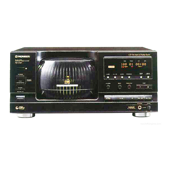
FILE-TYPE CD PLAYER
PD-F957
PD-F907
THIS MANUAL IS APPLICABLE TO THE FOLLOWING MODEL(S) AND TYPE(S).
TE
Type
L 13942296513
PD-F957
KU
KC
KU/CA
CONTENTS
1. SAFETY INFORMATION .................................... 2
2. EXPLODED VIEWS AND PARTS LIST ............. 3
3. SCHEMATIC DIAGRAM ................................... 11
4. PCB CONNECTION DIAGRAM ....................... 19
5. PCB PARTS LIST ............................................. 24
6. ADJUSTMENT .................................................. 28
7.GENERAL INFORMATION ............................... 36
7.1 PARTS ........................................................ 36
www
7.1.1 IC .......................................................... 36
7.1.2 DISPLAY ............................................... 37
.
PIONEER ELECTRONIC CORPORATION
PIONEER ELECTRONICS SERVICE, INC. P.O. Box 1760, Long Beach, CA 90801-1760, U.S.A.
PIONEER ELECTRONIC (EUROPE) N.V . Haven 1087, Keetberglaan 1, 9120 Melsele, Belgium
PIONEER ELECTRONICS ASIACENTRE PTE. LTD. 501 Orchard Road, #10-00 Lane Crawford Place, Singapore 0923
C C C C C PIONEER ELECTRONIC CORPORATION 1997
http://www.xiaoyu163.com
Model
PD-F907
-
O
AC120V
-
O
AC120V
O
-
AC120V
x
ao
y
i
http://www.xiaoyu163.com
8
D
FILE-TYPE
COMPACT DISC PLAYER
PD-F905
Î
ACSESS
SINGLE
PLAY
LOADER
FILE -TYME CD MECHANISM
Q Q
Power Requirement
3
6 7
1 3
7.2 DIAGNOSIS ................................................ 39
7.2.1 ERROR CORD DISPLAY ................. 39
7.2.3 ERROR HISTORY DISPLAY ............ 40
7.2.4 DISASSEMBLY ................................. 41
7.3 BLOCK DIAGRAM ...................................... 49
................................................................... 50
u163
.
4-1, Meguro 1-Chome, Meguro-ku, Tokyo 153, Japan
2 9
9 4
2 8
DISC
TRACK
MIN
SEC
TITLE
TITLE
MODE
HI-LITE
CLEAR
PROGRAM
INPUT
DISPLAY
UNLOAD
BEST
PREVIOUS
DISC
OPEN/
CLOSE
Remarks
1 5
0 5
8
2 9
9 4
m
co
T-ZZY DEC. 1997 Printed in Japan
9 9
ORDER NO.
RRV1898
2 8
9 9
Advertisement
Table of Contents

Related Manuals for Pioneer PD-F957


Summary of Contents for Pioneer PD-F957
-
Page 1: Table Of Contents
PIONEER ELECTRONICS SERVICE, INC. P.O. Box 1760, Long Beach, CA 90801-1760, U.S.A. PIONEER ELECTRONIC (EUROPE) N.V . Haven 1087, Keetberglaan 1, 9120 Melsele, Belgium PIONEER ELECTRONICS ASIACENTRE PTE. LTD. 501 Orchard Road, #10-00 Lane Crawford Place, Singapore 0923 C C C C C PIONEER ELECTRONIC CORPORATION 1997 T–ZZY DEC. -
Page 2: Safety Information
For the latest information, always consult the current Also test with plug reversed PIONEER Service Manual. A subscription to, or ad- u163 (Using AC adapter ditional copies of, PIONEER Service Manual may be plug as required) obtained at a nominal charge from PIONEER. -
Page 3: Exploded Views And Parts List
See Contrast table (2) Mirror Mat Z23 - 0204 Battery (R6P, AA) VEM - 013 9(1/2) (2) CONTRAST TABLE PD-F907/KU,KC and PD-F957/KU/CA have the same construction except for the following: Part No. Mark No. Symbol & Description Remarks PD-F957/ PD-F907/... - Page 4 PD-F957,PD-F907 3 7 63 1515 0 2.2 EXTERIOR KU/CA,KU type only L 13942296513 PD-F907 only PD-F907 only u163 http://www.xiaoyu163.com...
- Page 5 32(3/4) ''2.3 LOADING MECHANISM 32(4/4) ASSY'' Note1 32(2/4) 21(1/2) 32(1/4) L 13942296513 Note1 21 (2/2) Note2 21(1/2) 26(2/2) 26(1/2) Note1 cutting position Note2 cutting position No.21(Back Fence) cutting No.26(Hood Base) 26(2/2) 21(2/2) cutting cutting 21(1/2) PD-F957 Only 26(1/2) u163 http://www.xiaoyu163.com...
- Page 6 Belt PEB1288 Binder Z09 - 056 Motor Pulley PNW1634 Disc Rack PNW2632 (2) CONTRAST TABLE PD-F907/KU,KC and PD-F957/KU/CA have the same construction except for the following: Part No. Mark No. Symbol & Description Remarks PD-F957/ PD-F907/ PD-F907/ KU/CA Main Board Assy...
- Page 7 PD-F957,PD-F907 3 7 63 1515 0 2.3 LOADING MECHANISM ASSY L 13942296513 u163 http://www.xiaoyu163.com...
- Page 8 PD-F957,PD-F907 3 7 63 1515 0 LOADING MECHANISM ASSY PARTS LIST Mark No. Description Parts No. ………… ………… Loading Motor Board Assy PWZ3337 Load SW Board Assy PWZ3334 Arm A Spring2 ABH7124 Gear Plate Spring ABH7051 Clamp Spring ABH7107 …………...
- Page 9 PD-F957,PD-F907 3 7 63 1515 0 2.4 SERVO MECHANISM ASSY GM L 13942296513 How to Install the Disc Table Use nipper or other tool to cut the three sections marked in figure . Then remove the spacer While supporting the spindle motor shaft with the stopper, put spacer on top of the yoke M, and stick the disc table on top (takes about 9kg pressure).
- Page 10 PD-F957,PD-F907 3 7 63 1515 0 SERVO MECHANISM ASSY GM PARTS LIST Mark No. Description Parts No. Gear 1 PNW2052 Gear 2 PNW2053 Gear 3 PNW2054 Carriage Base PNW2699 Pickup Assy - S PEA1335 D.C. Motor Assy (SPINDLE) PEA1235...
-
Page 11: Schematic Diagram
PD-F957,PD-F907 3. SCHEMATIC DIAGRAM 3 7 63 1515 0 Note: When ordering service parts, be sure to refer to "EXPLODED VIEW AND PARTS LIST" or "PCB PARTS LIST". 3.1 MECHANISM BOARD ASSY,SENSOR BOARD ASSY,LOAD SW BOARD ASSY,SELECT MOTOR BOARD ASSY,LOADING MOTOR BOARD ASSY,CENTER LED BOARD ASSY,... - Page 12 PD-F957,PD-F907 3.2 MAIN BOARD ASSY AND POWER BOARD ASSY (FOR PD-F957) 3 7 63 1515 0 2 23 1.8V -O.7V 1.8V 1.6V 1.6V 1.6V 1.6V 1.7V 0.2V 1.7V L 13942296513 (SEL) 3.4V (SEL) 5.0V (SEL) SIGNAL ROUTE : AUDIO SIGNAL...
- Page 13 PD-F957,PD-F907 3 7 63 1515 0 IC301(CXD2529Q) :PLAY MODE 3 - 4 PIN No. Voltage(V) 1.2-1.3 1.2-1.4 0.05 PIN No. 50-55 Voltage(V) 2.6-2.7 PIN No. 84-86 89-90 91-92 93-95 Voltage(V) 1.6V LINE OUT -9.2 JACK -9.2 1.6V L 13942296513...
- Page 14 PD-F957,PD-F907 3.3 MAIN BOARD ASSY AND POWER BOARD ASSY (FOR PD-F907) 3 7 63 1515 0 2 23 MAIN BOARD ASSY (PWZ3400) 1.8V -O.7V 1.8V 1.6V 1.6V 1.6V 1.6V 1.7V 0.2V 1.7V L 13942296513 (SEL) 3.4V (SEL) 5.0V (SEL)
- Page 15 PD-F957,PD-F907 3 7 63 1515 0 IC301(CXD2519Q) :PLAY MODE 3 - 4 PIN No. 1.2-1.3 1.2-1.4 0.05 Voltage(V) PIN No. 50-55 Voltage(V) 2.6-2.7 PIN No. 84-86 89-90 91-92 93-95 Voltage(V) 1.6V LINE OUT -9.2 JACK -9.2 1.6V L 13942296513...
- Page 16 S753 : POWER STAND/ON S717 : CLEAR S708 : OPEN/CLOSE S718 : PGM S709 : HI-LITE S719 : TITLE INPUT (PD-F957) S710 : 7 : RANDOM (PD-F907) S711 : 4 1 S720 : TITLE DISPLAY (PD-F957) S712 : ¡ ¢...
- Page 17 PD-F957,PD-F907 3 7 63 1515 0 ∗1 50T-JUMP: After switching to the pause mode, press Waveforms the manual search key. ∗2 FOCUS-IN: Press the play key without loading a disc. Note: The encircled numbers denote measuring point in the schematic diagram.
- Page 18 PD-F957,PD-F907 3 7 63 1515 0 Waveforms IC202-Pin 9: TRACK SEARCH MODE IC301-Pin 54 : PLAY MODE (1kHz) (CADR) (BCK) 2V/div 200msec/div 2V/div 500nsec/div – GND – GND IC301-Pin 50 : PLAY MODE (1kHz) IC301-Pin 27 : PLAY MODE (MDP) 2V/div 2 µsec/div...
-
Page 19: Pcb Connection Diagram
For further information for respective destinations, 2. A comparison between the main parts of PCB and For PD-F957 be sure to check with the schematic diagram. G S D schematic diagrams is shown below. - Page 20 PD-F957,PD-F907 4.2 MAIN BOARD ASSY (FOR PD-F957) 3 7 63 1515 0 SIDE A To PICKUP ASSY MAIN BOARD ASSY CN610 J657 L 13942296513 J601 J1601 u163 J631 CN701 PNP1443–A http://www.xiaoyu163.com...
- Page 21 PD-F957,PD-F907 3 7 63 1515 0 4.3 DISPLAY BOARD ASSY,SWITCH BOARD ASSY AND POWER BOARD ASSY (FOR PD-F957) SIDE A SWITCH BOARD ASSY DISPLAY BOARD ASSY CN351 L 13942296513 IC702 Q702 IC701 Q701 CN11 POWER BOARD ASSY u163 IC21 IC41...
- Page 22 PD-F957,PD-F907 4.4 MAIN BOARD ASSY(FOR PD-F907) 3 7 63 1515 0 To PICKUP ASSY SIDEA MAIN BOARD ASSY CN610 J657 L 13942296513 J601 J1601 u163 J631 CN701 PNP1421–C http://www.xiaoyu163.com...
- Page 23 PD-F957,PD-F907 3 7 63 1515 0 4.5 DISPLAY BOARD ASSY,SWITCH BOARD ASSY AND POWER BOARD ASSY (FOR PD-F907) SIDE A SWITCH BOARD ASSY DISPLAY BOARD ASSY CN351 L 13942296513 Q711 CN11 POWER BOARD ASSY u163 IC31 IC21 IC33 IC23...
-
Page 24: Pcb Parts List
PD-F957,PD-F907 3 7 63 1515 0 5. PCB PARTS LIST NOTES : ÷ Parts marked by “ NSP ” are generally unavailable because they are not in our Master Spare Parts List. ÷ The mark found on some component parts indicates the importance of the safety factor of the part. - Page 25 PD-F957,PD-F907 3 7 63 1515 0 PARTS LIST FOR PD-F957/KU/CA Mark No. Description Parts No. Mark No. Description Parts No. MAIN BOARD ASSY (PWZ3663) Other Resistors RD1/4PU&&&J OTHERS SEMICONDUCTORS CN207 MT 4P CONNECTOR 173981-4 IC151 CXA1782CQ CN208 3P JUMPER CONNECTOR...
- Page 26 PD-F957,PD-F907 3 7 63 1515 0 Mark No. Description Parts No. Mark No. Description Parts No. CAPACITORS LOADING MOTOR BOARD ASSY C712 CEAT100M50 LOADING MOTOR BOARD assembly has no service part. C705,C709 CEAT101M10 C711 CEAT4R7M50 MECHANISM BOARD ASSY C708...
- Page 27 PD-F957,PD-F907 3 7 63 1515 0 PARTS LIST FOR PD-F907/KU/KC Mark No. Description Parts No. Mark No. Description Parts No. MAIN BOARD ASSY(PWZ3400) RESISTORS R189 RD1/4VM163J SEMICONDUCTORS R157 RD1/4VM274J (10k Ω) VR153,VR155 RCP1045 IC151 CXA1782CQ (22k Ω) VR151,VR152,VR154 RCP1046...
-
Page 28: Adjustment
PD-F957,PD-F907 3 7 63 1515 0 6. ADJUSTMENT 6.1 PREPARATIONS 6.1.1 Jigs and Measuring Instruments 8 Cm DISC CD TEST DISC screwdriver screwdriver screwdriver (With at last about 20 (YEDS-7) (small) (medium) (large) minutes recording) 39 kΩ 0.001µF Dual-trace... - Page 29 PD-F957,PD-F907 3 7 63 1515 0 6.2 ADJUSTMENT 6.2.1 How to Start/Cancel Test Mode TEST MODE : ON PD-F957 MODEL PD-F957 MODEL W115 W115 W102 W102 Short Point Short Point MAIN BOARD ASSY MAIN BOARD ASSY PD-F907 MODEL PD-F907 MODEL...
- Page 30 PD-F957,PD-F907 3 7 63 1515 0 6.2.3 Check and Adjustment 1. Focus Offset Adjustment Test mode DC voltage VR154 0±50mV None disc MAIN BOARD ASSY Oscilloscope DC Mode V: 5mV/div H: 10mSec/div Player START (CN201) Prove (10:1) MAIN BOARD ASSY L 13942296513 2.
- Page 31 PD-F957,PD-F907 3 7 63 1515 0 3. Tracking Error Barance Adjustment Test mode SPDL servo CLOSE FOCUS servo CLOSE TRKG servo OPEN Innermost TEST DISC circumference VR155 (1 TRK) PLAY MAIN BOARD ASSY Oscilloscope DC Mode V: 10mV/div Player...
- Page 32 PD-F957,PD-F907 3 7 63 1515 0 5. RF Level Adjustment Test mode SPDL servo CLOSE FOCUS servo CLOSE 1.2VP-P TRKG servo CLOSE ±0.1V Innermost TEST DISC circumference VR153 (1 TRK) PLAY MAIN BOARD ASSY Oscilloscope AC Mode V: 50mV/div...
- Page 33 PD-F957,PD-F907 3 7 63 1515 0 7. RF Level Adjustment Check Test mode CLOSE SPDL servo FOCUS servo CLOSE TRKG servo CLOSE 1.2VP-P ±0.1V Innermost TEST DISC circumference VR153 (1 TRK) PLAY MAIN BOARD ASSY Make adjustment if the value exceeds the specified range.
- Page 34 PD-F957,PD-F907 3 7 63 1515 0 9. Focus Best Adjustment Test mode SPDL servo CLOSE FOCUS servo CLOSE TRKG servo CLOSE Innermost TEST DISC circumference VR156 (1 TRK) Adjust the RF level to maximum, with PLAY MAIN BOARD ASSY the focus error voltage within ±150mV.
- Page 35 PD-F957,PD-F907 3 7 63 1515 0 11. Focus Best Adjustment Adjust this point only if adjustment was made in item 10. Test mode SPDL servo CLOSE FOCUS servo CLOSE TRKG servo CLOSE Innermost TEST DISC circumference VR156 (1 TRK)
-
Page 36: General Information
PD-F957,PD-F907 3 7 63 1515 0 The information shown in the list is basic information and may 7. GENERAL INFORMATION not correspond exactly to that shown in the schematic diagrams. 7.1 PARTS No. Pin Name Function STBL Standby - led /osce. -
Page 37: Display
PD-F957,PD-F907 3 7 63 1515 0 7.1.2 DISPLAY PEL1095(V701: DISPLAY BOARD ASSY) :FOR PD-F957 ¶ Pin Assignment CUSTOM ALL BEST REPEAT CDTEXT SINGLE PREVIOUS DISC SCAN ADLC REMAIN ¶ Anode Grid Assignment L 13942296513 ¶ Pin Connection u163 http://www.xiaoyu163.com... - Page 38 PD-F957,PD-F907 3 7 63 1515 0 PEL1089(V701: DISPLAY BOARD ASSY) :FOR PD-F907 ¶ Pin Assignment ¶ Anode Grid Assignment L 13942296513 ¶ Pin Connection u163 http://www.xiaoyu163.com...
-
Page 39: Diagnosis
The previously generated errors (NG processing) can be confirmed in the test mode. Since the has a backup function, the error history is memorized even if the power is turned off. (Memory holding time : About two days) TEST MODE: ON PD-F957 MODEL PD-F957 MODEL W115... -
Page 40: Error History Display
PD-F957,PD-F907 3 7 63 1515 0 7.2.3 ERROR HISTORY DISPLAY (1) Disc No. A : Detail of error code at portion <Note> The user display appears only when the normal operation cannot be returned even if the fail safe operation is executed after each error occurs. -
Page 41: Disassembly
PD-F957,PD-F907 3 7 63 1515 0 7.2.4 DISASSEMBLY REMOVING THE LOADING MECHANISM ASSY Remove the each wire. Remove the Bonnet. 1 2 1 4 Remove the Screws and Stopper Angle. While holding down the hook of the Mecha Base, slide the Loading Mechanism Assy to Remove the Screws and Rear Base. - Page 42 PD-F957,PD-F907 3 7 63 1515 0 REMOVING THE OPERATION PANEL Remove the Bonnet. Remove the Screws. Cut the Binder securing the wire material. Remove the Center Pole. (Refer to the “REMOVING THE DISC RACK”) Shift the Front Panel slightly toward you while paying attention to the back side hooks on the Chassis.
- Page 43 PD-F957,PD-F907 3 7 63 1515 0 REMOVE THE HOOD AND HOOD BASE Remove the Bonnet. Remove the Operation Panel. (Refer to the “REMOVING THE OPERATION PANEL”) Remove the Screws. Remove the Back Fence. Press the hook of the Stopper of the Hood Base to remove the Stopper. Slide the Hood toward the left to remove the Hood.
- Page 44 PD-F957,PD-F907 3 7 63 1515 0 INSTALLING THE LOADING MECHANISM ASSY Loading Mechanism Assy Slider The projection of the Drive Plate should be engaged with the corresponding part of the slider L 13942296513 INSTALLING THE DISC RACK The hook of the Mecha Base should...
- Page 45 PD-F957,PD-F907 3 7 63 1515 0 REMOVING THE SERVO MECHANISM ASSY GM Remove the connector ASSY (4P) from the float base. Turn gear pulley (B) and position Arm (A) as shown below. Remove the float spring. (To install this part, line up...
- Page 46 PD-F957,PD-F907 3 7 63 1515 0 REMOVING THE ARM (A) Remove the float base together with the Servo Mechanism ASSY GM. (Refer to Steps “ Removing the Servo Mechanism ASSY GM” .) Turn gear pulley (B) and position Arm (A) as shown below.
- Page 47 PD-F957,PD-F907 3 7 63 1515 0 FOR REASSEMBLY, REVERSE THE DISASSEMBLY PROCEDURE, AND IN ADDITION CARRY OUT THE FOLLOWING ITEMS. Assemble the arm plate as shown below, watching out for the drive plate hook. Drive Plate Hook Arm Plate...
- Page 48 PD-F957,PD-F907 3 7 63 1515 0 Gear Pulley(B) Arm(A) Turn Arm(B) Install Arm(A) Arm(B) Gear Plate L 13942296513 Clamper Holder Gear Pulley(B) 45° u163 Clamp Spring http://www.xiaoyu163.com...
-
Page 49: Block Diagram
PD-F957,PD-F907 3 7 63 1515 0 7.3 BLOCK DIAGRAM L 13942296513 u163 http://www.xiaoyu163.com... -
Page 50: Panel Facilities And Specifications
PD-F957,PD-F907 3 7 63 1515 0 8. PANEL FACILITIES AND SPECIFICATIONS FRONT PANEL HI-LITE button CLEAR button Hood MODE button PROGRAM button Remote sensor TITLE INPUT button SINGLE LOADER FILE–TYPE COMPACT DISC PLAYER TITLE DISPLAY button DISC TRACK ACCESS button PD-F905 Î... - Page 51 PD-F957,PD-F907 3 7 63 1515 0 SPECIFICATION 1. General 3. Output terminal Type ........... Compact disc digital audio system Audio line output Power requirements Control input jack (Except for U.K. model) U.S. and Canadian models ....... AC 120V, 60 Hz Control output jack (Except for European and U.K.
- Page 52 http://www.xiaoyu163.com 3 7 63 1515 0 L 13942296513 u163 http://www.xiaoyu163.com...
- Page 53 http://www.xiaoyu163.com 3 7 63 1515 0 AUDIO SPECIFICATIONS Frequency response ..........2Hz to 20 kHz Signal to noise ratio ..........More than 98 dB Dynamic range ............. More than 96 dB THD ............1kHz: 0.003% maximum Output voltage ..............2 Vrms Channel balance ..........
- Page 54 http://www.xiaoyu163.com 3 7 63 1515 0 L 13942296513 u163 RadioShack A Division of Tandy Corporation Fort Worth, Texas 76102 RRV1971M ZZY Printed in Japan http://www.xiaoyu163.com...
Need help?
Do you have a question about the PD-F957 and is the answer not in the manual?
Questions and answers