Vertex Standard VX-2200 series Operating Manual
Hide thumbs
Also See for VX-2200 series:
- Service manual (84 pages) ,
- Operating manual (21 pages) ,
- Operating manua (21 pages)

Related Manuals for Vertex Standard VX-2200 series


Summary of Contents for Vertex Standard VX-2200 series
- Page 1 VX-2200 ( LTR ) S erieS perating anual Vertex Standard LMR, Inc. 4-6-8 Shibaura, Minato-ku, Tokyo 108-0023, Japan...
- Page 2 We’re glad you joined the Vertex Standard team. Call on us anytime, because com- munications is our business. Let us help you get your message across.
- Page 3 Important channel frequency data is stored in EEPROM and flash memory on the CPU, and is easily programmable by dealers using a personal computer and the Vertex Standard Programming Cable and CE94 Software. The pages which follow will detail the many advanced features provided on the VX-2200 ( LTR ) Series transceiver.
- Page 4 ! Fcc rF e arning xpOsure equireMents ATTENTION! BEFORE USING THE RADIO, READ THE “PRODUCT SAFETY GUIDE” CHAPTER ON STARTING FROM PAGE 4 FOR MOBILE TWO-WAY RADIOS WHICH CONTAINS IMPORTANT OPER- ATING INSTRUCTIONS FOR SAFE USAGE AND RF ENERGY AWARENESS AND CONTROL FOR COMPLIANCE WITH APPLI- CABLE STANDARDS AND REGULATIONS.
- Page 5 ! ic rss g arning eneral equireMents English r This device complies with Industry Canada license-exempt RSS standard(s). Operation is subject to the following two conditions: (1) this device may not cause interference, and (2) this device must accept any interference, including interference that may cause undesired operation of the device.
- Page 6 RF exposure for both workers and the general public. These recommended RF exposure levels include substantial margins of protection. All Vertex Standard two-way radios are designed, manufactured, and tested to en- sure they meet government-established RF exposure levels. In addition, manufac- turers also recommend specific operating instructions to users of two-way radios.
-
Page 7: Compliance With Rf Exposure Standard
Compliance with RF Exposure Standard Your Vertex Standard two-way radio is designed and tested to comply with a num- ber of national and international standards and guidelines (listed below) regarding human exposure to radio frequency electromagnetic energy. This radio complies... - Page 8 rOduct aFety uide RF Exposure Compliance and Control Guidelines and Operating Instructions To control exposure to yourself and others and to ensure compliance with the RF exposure limits, always adhere to the following procedures. uidelines User awareness instructions should accompany device when transferred to ...
-
Page 9: Mobile Antenna Installation Guidelines
rOduct aFety uide When a mobile radio is used in conjunction with another co-located transmit- ter such as a Vehicular Repeater, it is the vehicle operator’s responsibility to take appropriate steps to keep bystanders at the required separation distance from the vehicle to ensure compliance with the FCC’s RF energy exposure limits for the general population. -
Page 10: Compliance And Control Guidelines And Operating Instructions For Mobile Two-Way Radios Installed As Fixed Site Control Stations
rOduct aFety uide Compliance and Control Guidelines and Operating Instructions for Mobile Two-Way Radios Installed as Fixed Site Control Stations If mobile radio equipment is installed at a fixed location and operated as a control station or as a fixed unit, the antenna installation must comply with the following requirements in order to ensure optimal performance and compliance with the RF energy exposure limits in the standards and guidelines listed above: The antenna should be mounted outside the building on the roof or a tower if... -
Page 11: Mounting Bracket Installation
nstallatiOn When installing the VX-2200 ( LTR ) transceiver, make sure to plan the installation carefully and leave additional room in the rear of the radio for cabling and acces- sory connections; in the front of the radio for access, controls, and cabling; and to the sides of the radio so that you may access and install the Knob Screws or Hex Head Bolts. -
Page 12: Mobile Installation
nstallatiOn Mobile Installation ower onnection VX-2200 ( LTR ) transceiver operates only in negative ground electrical systems. Before starting the installation, make sure that the ground polarity of the vehicle is correct. Accidentally reversing the polarity will not damage the transceiver, but will cause the cable fuses to blow. - Page 13 nstallatiOn r Connect the RED power cable lead to the POSITIVE ( + ) battery terminal, and the BLACK power cable lead to the NEGATIVE (–) terminal. If you need to extend the power cable, use #12 AWG or larger insulated, stranded copper wire.
-
Page 14: Base Station Installation
nstallatiOn Base Station Installation ower onnection Operation of the VX-2200 ( LTR ) transceiver from an AC line requires a power supply capable of providing at least 15 Amps continuously at 13.6 Volts DC. Please contact your dealer to select an optimal power supply that satisfy these re- quirements. - Page 15 nstallatiOn r As with all fixed site antenna installations, it is the responsibility of the licens- ee to manage the site in accordance with applicable regulatory requirements and may require additional compliance actions such as site survey measure- ments, signage, and site access restrictions in order to insure that exposure limits are not exceeded.
-
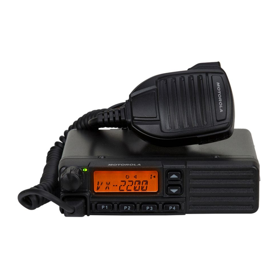
Page 16: Front Panel
Front Panel Important! - All buttons located on the Front Panel are Programmable Function (PF) Buttons, configured according to your network requirements and programmed by your Vertex Standard dealer. The instructions below describe a typically-config- ured radio. ... - Page 17 & c OntrOls OnnectOrs LCD (Liquid Crystal Display) The display includes a 8-character alpha-numeric section showing group name tags/identity information and error messages, and an upper icon row display- ing feature status (see below). TX/BUSY Indicator Indicates Transceiver’s Transmit/Receive Status onventionAl Steady Red: Transmitting in progress...
-
Page 18: Rear Panel
& c OntrOls OnnectOrs Rear Panel 13.6V DC Cable Pigtail with Connector The supplied DC power cable must be connected to this 2-pin connector. Use only the supplied fused cable, extended if necessary, for power connection. ... - Page 19 VX-2200 ( LTR ) S eRieS peRaTing anuaL...
-
Page 20: Setting The Volume
asic peratiOn OF the ransceiver Important! - Before turning on the radio the first time, confirm that the power con- nections have been made correctly and that a proper antenna is connected to the antenna jack. Switching Power ON/OFF r Turn the VOL/PWR knob turn on the radio. The display will become illuminated. r Press the [ ... -
Page 21: Automatic Time-Out Timer
asic peratiOn OF the ransceiver ltr Z r Press the PTT switch. r When a group is available, the TX/BUSY indicator will glow red. The radio is now transmitting. While holding in the PTT switch, speak across the face of the microphone in a clear and normal voice. For best transmission, hold the microphone about 1-1/2 to 2 inches away from your mouth. -
Page 22: Advanced Operation
For further details, contact your Vertex Standard dealer. For future reference, check the box next to the function that has been assigned to each PF button on your particular radio, and keep it handy. -
Page 23: Description Of Operating Functions
dvanced peratiOn Description of Operating Functions Moni ( M onitor Press (or press and hold) the assigned PF key to cancel CTCSS- and DCS-con- trolled squelch; the TX/BUSY indicator will glow green Press (or press and hold) the assigned PF key to open the SQL to hear background noise (unmute the audio);... - Page 24 dvanced peratiOn scAn The Scanning feature is used to monitor multiple channels programmed into the transceiver. While scanning, the transceiver will check each group which is pro- grammed with scan memory “Enabled” for the presence of a signal, and will stop on a channel if a signal is present.
-
Page 25: Public Address
Press (or press and hold) the assigned PF key to initiate an emergency call. For further details contact your Vertex Standard dealer. Press (or press and hold) the assigned PF key to send a 5-Tone sequential burst which is pre-defined. - Page 26 Press (or press and hold) the assigned PF key to lock the various aspects of the transceiver’s keys. The precise lockout configuration must be programmed by your Vertex Standard dealer. Ption This function is usable only when a FVP-35 Optional Unit is installed. It is used to toggle “on”...
-
Page 27: Arts (Auto Range Transpond System)
KILL status. When the radio is in the STUN status, the radio is not usable till a ra- dio receives a REVIVE code. When the radio is in the KILL status, the radio is not usable, please bring the radio to your Vertex Standard dealer. VX-2200 ( LTR ) S... -
Page 28: Optional Accessories
Connection Cable for FIF-12 CT-171 Availability of accessories may vary; some accessories are supplied standard per local requirements, others may be unavailable in some regions. Check with your VERTEX STANDARD Dealer for changes to this list. VX-2200 ( LTR ) S eRieS peRaTing... - Page 29 Olicy Vertex Standard warrants, to the original purchaser only, its Vertex Standard manu- factured communications products against defects in materials and workmanship under normal use and service for a given period of time from the date of purchase. Limited Warranty Details: North America customers (USA and Canada): ...
- Page 30 VX-2200 ( LTR ) S eRieS peRaTing anuaL...
- Page 31 Part 15.21: Changes or modifications to this device not expressly approved by Vertex Standard could void the user’s authorization to operate this device.
- Page 32 No portion of this manual may be reproduced without the per- mission of Vertex Standard LMR, Inc. Vertex Standard is a trademark of Vertex Standard LMR, Inc. All other trademarks are the property of their respective owners. ©2015 Vertex Standard LMR, Inc.
Need help?
Do you have a question about the VX-2200 series and is the answer not in the manual?
Questions and answers