
Related Manuals for Spheros CC 145


Summary of Contents for Spheros CC 145
- Page 1 Klimaanlage Betriebsanleitung Air Conditioning System Operating Instruction CC 145 05/2010 Ident Nr. 11114709A...
-
Page 2: Table Of Contents
Equipment General Arrangement ....13 1.1 Klimaanlage CC 145 ......1 1.1 Air conditioner CC 145 . -
Page 3: Geräteübersicht
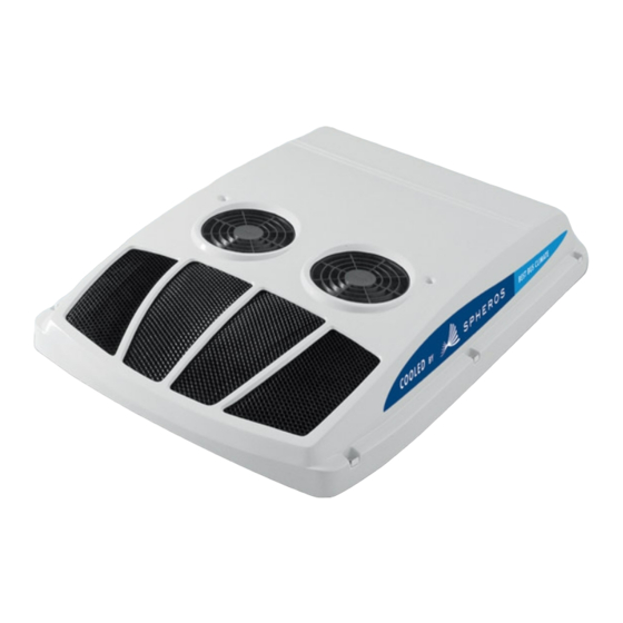
CC 145 Geräteübersicht 1.1 Klimaanlage CC 145 Die Klimaanlage CC 145 und ihre Hauptbauteile sind in Abb. 1 dargestellt. Abb. 1 CC 145... -
Page 4: Bedienelemente Und Anzeige
CC 145 Bedienelemente und Anzeigen 2.1 Bedienteil Auf dem Bedienteil der Klimaanlage befinden sich alle Bedienelemente und Anzeigen für Systemeinstellungen, Betriebsartenwahl und Betriebsanzeigen. Die Abb. 2 zeigt das Bedienteil mit seinen Bedienelementen und Anzeigen. Abb. 2 Bedienteil... -
Page 5: Funktion Der Bedienelemente Und Anzeiger
CC 145 2.2 Funktion der Bedienelemente und Anzeiger Orts- Bedienelemente / Einstel- Funktion zahl, Anzeiger lungen / Die Funktion der Bedienelemente und Anzeiger ist in Abb. 3 erklärt. Abb. 2 Anzeige LED Betriebsart leuchtet Betriebsart AUTO ist eingeschaltet, Anmerkung: AUTO Anlage arbeitet mit Klimaautomatik. -
Page 6: Betrieb
CC 145 geöffneter Kompressorkupplung blinkt die LED (3). Betrieb Um extrem kurze Schaltzyklen der Kompressorkupplung zu vermeiden, ist ein Mindestintervall von 30 Sekunden zwischen Aus- und Einschalten 3.1 Bedienung - Normalbetrieb programmiert. 3.1.1 Anzeigefeld 3.2 Bedienung - Betrieb bei Fehlern Das numerische Anzeigefeld informiert den Bediener über die gewählte... -
Page 7: Störungen An Der Elektrik
CC 145 Kältemittelmenge in der Anlage überprüfen. 3.3 Störungen an der Elektrik Die einzelnen Schaltkreise müssen gemäß Schaltplan systematisch geprüft nach ca. 5 Minuten Betrieb der Klimaanlage und geschlossener werden. Vor allem sollten Steckverbindungen und elektrische Bauteile wie Kompressorkupplung bei erhöhter Motordrehzahl darf der Kältemittelfluss Schalter, Relais, usw. -
Page 8: Wartung
CC 145 Wartung Die Riemenscheibe der Kompressorkupplung dreht sich während des Fahrzeugbetriebs ständig mit. Ein Verschleiß der Lager oder Schäden an der 4.1 Allgemeines Kupplung können somit völlig unabhängig von den Betriebsstunden der Eine Klimaanlage ist - so wie alle anderen Bauteile eines Fahrzeugs - ständig Klimaanlage auftreten. -
Page 9: Vorbeugende Wartung
CC 145 4.2 Vorbeugende Wartung Verdichter / Magnetventil Monatlich alle 3 Jährlich Die hier beschriebenen Maßnahmen der vorbeugenden Wartung betreffen Monate normale Betriebsbedingungen. Bei höherer Beanspruchung und Fahrten in Ölstand des Verdichters nach 15 stark belasteter Luft, müssen die Maßnahmen in entsprechend kürzeren Ab- Minuten Betrieb überprüfen... - Page 10 CC 145 Anmerkung: Elektrik Monatlich alle 3 Jährlich Wir empfehlen die vorliegende Tabelle zur Aufstellung eines eigenen, Monate regelmäßigen Wartungsplans Ihrer Fahrzeuge zu nutzen. Klemmen des Leistungskabels am Generator, Hauptsicherung ACHTUNG und Elektroanschlüsse über- Die Reinigung des Umluftfilters und des Verflüssigers in der Klimaanlage prüfen...
-
Page 11: Technische Daten
CC 145 Technische Daten Die folgende Abbildung listet die technischen Daten der Klimaanlage auf. CC 145 Kühlleistung max. (kW) Kühlleistung nominal (kW) Abmessungen L x B x H (mm) 1740 x 1200 x 200 Gewicht (kg) Luftdurchsatz (freiblasend, in m³ / h) -
Page 12: Fehlersuche Und -Beseitigung
CC 145 Fehlersuche und -beseitigung Für die Fehlersuche und -beseitigung listet die folgende Abbildung in Tabellenform mögliche Störungsanzeichen und die entsprechenden Maßnahmen zur Fehlerbeseitigung, um die einwandfreie Funktion der Anlage wieder herzustellen, auf. Störungsanzeichen Mögliche Ursache Maßnahmen Verdichter arbeitet nicht... - Page 13 CC 145 Störungsanzeichen Mögliche Ursache Maßnahmen Klimaanlage kühlt nicht Zu wenig Kältemittel Auf Undichtigkeiten prüfen, Kältemittel auf den richtigen Stand nachfüllen und Verdichter läuft stän- Luft oder anderes Gas in der Anlage Vakuum in der Anlage wieder herstellen (mindestens 3 Stunden bei unter 10 mbar), Filtertrockner auswechseln und Kältemittel auf den richtigen Stand...
-
Page 14: Schaltpläne
CC 145 Schaltpläne 7.1 Allgemeines Die Abbildung 7 ab Seite 25 zeigt die Schaltpläne der Klimaanlage CC 145. Bei Leitungen ohne Angabe der Stärke beträgt der Querschnitt 0,75 mm². -
Page 15: Equipment General Arrangement
CC 145 Equipment General Arrangement 1.1 Air conditioner CC 145 The air conditioner type CC 145 and its main components are shown in Fig. 1. Fig. 1 CC 145... -
Page 16: Controls And Indicators
CC 145 Controls and Indicators 2.1 Control Panel The air conditioner control panel has all controls and indicators for system settings, mode switching and operational indications. The control panel and its controls and indicators are shown in Fig. 2. Fig. 2 Control Panel... -
Page 17: Function Of Controls And Indicators
CC 145 2.2 Function of Controls and Indicators Index Control / Indicator Setting / Function Fig. 2 Indication The function of the controls and indicators is shown in Fig. 3. AUTO mode LED AUTO mode is on, system operates in AUTO mode. -
Page 18: Equipment Operation
CC 145 LO (1 time), HI (2 times) and back to AUTO mode (3 times). Equipment Operation The LED (3) illuminates, if the compressor clutch is closed. If the compressor clutch is open, the LED (3) blinks. 3.1 Command Description - Normal Operation To prevent short operation cycles of the compressor clutch, an interval of 30 seconds between ON and OFF is programmed. -
Page 19: Electrical Malfunctions
CC 145 Check the refrigerant charge in the system. 3.3 Electrical Malfunctions The individual circuits are to be checked systematically in accordance with After the air conditioning system has been operating for approx. 5 min. the wiring diagram. with the electromagnetic clutch activated and the engine running at rapid... -
Page 20: Maintenance Activities
CC 145 Maintenance Activities During long term non-use the air-conditioning system should be operated for about 15 minutes at least once a month in order to prevent the shaft seals of 4.1 General the refrigerant compressor from hardening. A requirement for this is a An air-conditioning system is - just as all the other parts of a vehicle - minimum outside temperature of >... -
Page 21: Preventive Maintenance
CC 145 4.2 Preventive Maintenance Compressor / compressor clutch every all 3 every The below listed actions are performed for normal operation. month months year If the system will be operated with high workload or in areas with air contam- After 15 minutes operation, check ination the actions have to be carried out in shorter time periods. - Page 22 CC 145 Electrical system every all 3 every Note: month months year We propose to use the tables for the preparation of maintenance plans for Check the connections of the your fleet. electrical power cable at the alternator for condition, damage...
-
Page 23: Technical Specification
CC 145 Technical Specification The following figure lists the main specification of the air condition system. CC 145 Max. cooling capacity (kW) Cooling capacity (kW) Dimensions Length x Width x Height (mm / in.) 1740 x 1200 x 200 / 68.5 x 47.3 x 7.9 Weight (kg/lbs) 67 / 147.7... -
Page 24: Failure Diagnosis Table
CC 145 Failure Diagnosis Table For troubleshooting the following figure lists possible malfunctions and symptoms and the remedial action to be taken to restore the system's serviceability. Symptoms Probable cause Solution Compressor does not work Fuse or relay defective Replace fuse or relay... - Page 25 CC 145 Symptoms Probable cause Solution AC does not cool down and Lack of refrigerant Check for leakage, fill to correct amount the compressor remains on Air or other gas in the system Draw a vacuum (min. 3 hours below 10 mbar) replace filter drier, fill to correct...
-
Page 26: Wiring Diagrams
CC 145 Wiring Diagrams 7.1 General The figure 7, starting on Page 25, shows the wiring diagrams of the CC 145 air conditioning system. Wirings without cross section have 0,75 mm². - Page 27 CC 145 Abb. 7 Schaltplan / Wiring diagram 12 V (Seite/Page 1 von/of 4)
- Page 28 CC 145 Abb. 7 Schaltplan / Wiring diagram 24 V (Seite/Page 2 von/of 4)
- Page 29 CC 145 Abb. 7 Relaistafel / Relay board 12 V (Seite/Page 3 von/of 4)
- Page 30 CC 145 Abb. 7 Relaistafel / Relay board 24 V (Seite/Page 4 von/of 4)
Need help?
Do you have a question about the CC 145 and is the answer not in the manual?
Questions and answers