Table of Contents
Advertisement
Quick Links
Advertisement
Table of Contents

Related Manuals for Digifly AIR-BT


Summary of Contents for Digifly AIR-BT
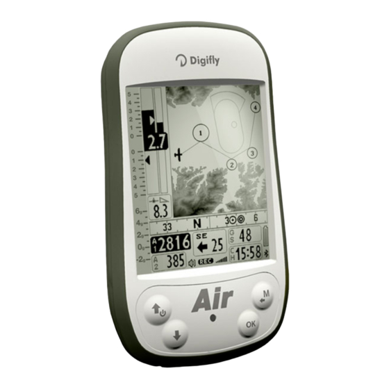
- Page 1 DIGIFLY AIR-BT AIR-SE Rev. 64a English (Firmware 244)
- Page 2 - Damage is caused by accidents including but not limited to lightning, water or fire, misuse or neglect, or every malfunction not related to manufacturing defects of your instruments. If your Digifly product is not working correctly or is defective, please contact your Digifly dealer. In order to avoid unnecessary inconvenience.
-
Page 3: Table Of Contents
INDEX INDEX................................3 GETTING STARTED ............................7 CONNECTIONS ................................7 BATTERY ..................................7 2.2.1 BATTERY RECHARGE ............................7 2.2.2 EXTERNAL POWER SUPPLY..........................7 KEYBOARD - NORMAL OR LONG KEY PRESS ......................7 TURNING ON & OFF ..............................8 DISPLAY CONTRAST ADJUSTMENT..........................8 MENU ...................................8 2.6.1 STANDARD FIELDS EDITING..........................8 2.6.2 ALPHANUMERICAL FIELDS EDITING.........................8 MULTI LANGUAGE HELP..............................9... - Page 4 4.2.1 10 SENSORS VARIOMETER WITH SELF-ADAPTIVE SENSITIVITY ..............21 4.2.2 DIGITAL VARIO..............................22 4.2.3 ANALOGICAL VARIO ............................22 4.2.4 INTEGRATED (AVERAGE) VARIO........................22 4.2.5 NETTO VARIO (WITH OPTIONAL PITOT TUBE) ....................22 4.2.6 INTEGRATED VARIO / NETTO VARIO AUTOMATIC SWITCH ................. 22 4.2.7 McCREADY (WITH OPTIONAL PITOT TUBE)....................
- Page 5 BLUETOOTH CONNECTION (AIR-BT ONLY)......................51 13.2.1 BLUETOOTH “PAIRING”........................... 51 13.2.2 BLUETOOTH COMMUNICATION WITH MANAGEMENT SOFTWARE OF THE INSTRUMENT......51 13.2.3 BLUETOOTH COMMUNICATION WITH SOFTWARE DECODING THE DIGIFLY TELEMETRY ......51 SOFTWARE..............................53 14.1 AIR MANAGEMENT SOFTWARE..........................53 14.1.1 SOFTWARE Digifly AirTools (PC, MAC) ......................53...
- Page 6 FOR FIRMWARE UPDATE (PC, MAC) ..............58 IGIFLY PDATER 14.2.1 FIRMWARE UPDATE PROCEDURE ......................... 58 DIGIFLY TELEMETRY HIGH SPEED REAL TIME DATA OUTPUT (AIR-BT ONLY) ..........59 15.1.1 ACTIVATE DIGIFLY TELEMETRY DATA OUTPUT ..................... 59 15.1.2 TELEMETRY DATA SELECTION ........................59 15.2...
-
Page 7: Getting Started
SD slot mini USB connector The dual purpose mini USB socket allows the Digifly AIR to be recharged via the supplied Digifly 5v charger and additionally connection to a personal computer or to a MAC for configuring & managing flight data. -
Page 8: Turning On & Off
To turn off your Digifly instrument, press the key at least for 4 seconds. After switching off your Digifly instrument, you must wait at least 5 seconds before attempting to turn it on again. This prevents unwanted operation. After turning on your Digifly instrument, the first screen briefly shows the vario model, pilot name (if set), logger status, vario serial number, software version, date, time and battery voltage. -
Page 9: Multi Language Help
IMPORTANT: after every firmware update, it is necessary to update also the help file containing the help messages. The help file update can be performed from your PC MAC using the Digifly AirTools, function: “upload HELP”. -
Page 10: Quick Reference Guide
QUICK REFERENCE GUIDE 3.1 PAGES The Digifly AIR features 13 pages. to manually change the pages press the keys (forward) or (backward). 3.1.1 MAIN PAGES (MASTER) There are 3 main pages (master) that for safety reasons can not be changed or disabled... -
Page 11: Configurable
OFF = the layout view of the page is disabled (the page will be skipped) ON = will show the corrisponding layout of the preset page uploaded by Digifly (Preset pages 1,2,3,4,5) FULL = will show the corrisponding layout of the page "User page 1,2,3,4,5" created and uploaded by the user using the free Digifly program AirPageConfigurator (for more details about software usage refer to chapter 14.1.2) -
Page 12: Symbols
3.2 SYMBOLS Battery level Bluetooth activated Normal icon = GPS FIX valid (GPS position available) Blinking icon = low GPS signal (GPS position NOT available) Flight recorder on Volume level Direction toward the center of the current Waypoint Direction toward the current WP accordingly to the optimized route Direction toward the current WP accordingly to the optimized route Last thermal direction Direction from which the wind is coming... -
Page 13: Master Plotter
3.3 MASTER PLOTTER PAGE Distance to WP cylinder Altimeter A1 Current glide ratio Required glide ratio to McCready WP cylinder Analogical Vario Analogival Air speed Digital Vario Optimal speed to fly STF Analogical vario scale Digital Air speed Estimated arrival height McCready equivalent over the WP cylinder Ground speed GPS... -
Page 14: Variometer (Plotter Page)
3.3.1 VARIOMETER (PLOTTER PAGE) In the area dedicated to the vario information are shown: o Digital vario; o average vario / Netto vario; o McCready value; o Equivalent McCready value 3.3.2 AIR SPEED / GROUND SPEED (PLOTTER PAGE) In the area dedicated to the anemometer information are shown: o Scrolling Analog format value Airspeed IAS/TAS;... -
Page 15: Hsi Navigation (Plotter Page)
3.3.5 HSI NAVIGATION (PLOTTER PAGE) In the center part is shown the HSI, a graphical navigation tool made by two dashed lines that intersect each other indicating the current WPT and its real height. Flying towards the center of the WPT cylinder, the airplane icon moves right or left of the dashed vertical line in case of rong route and up or down the dashed horizontal line telling us the arrival height with the current gliding ratio 3.3.6... -
Page 16: Master Compass
3.4 MASTER COMPASS PAGE Clock Analogical Altimeter A1 Digital Altimeter A1 Chronometer Analogical vario scale Current glide ratio McCready Analogival Air speed McCready equivalent Optimal speed to fly STF Analogical Vario Digital Air speed Digital Vario WP name Averag.Vario / NettoVario analogical Compass main points Direction to WP icons... -
Page 17: Variometer (Compass Page)
3.4.1 VARIOMETER (COMPASS PAGE) In the area dedicated to the vario information are shown: o Digital vario; o average vario / Netto vario; o McCready value; o Equivalent McCready value 3.4.2 AIR SPEED / GROUND SPEED (COMPASS PAGE) In the area dedicated to the anemometer information are shown: o Scrolling Analog format value Airspeed IAS/TAS;... -
Page 18: Master Info Gps
3.5 MASTER INFO GPS PAGE GPS coordinates type Latitude GPS signal quality Longitude GPS Altitude Ground speed GPS Waypoint Start In Tracking direction Previous Waypoint Date and Time Current Waypoint GPS signal Next Waypoint Battery level Bluetooth ON Flight recorder ON Volume level ●... -
Page 19: Gps Status Information
MASTER INFO GPS page, are visible all values relative to your GPS position and particular fuctions available only In the on this layout: function “take me here” (GOTO HOME), function “save current position” (MARK), function “cancel current navigation” (CLEAR NAV) and supervision real time function "Real Time Navigation Manager" of progress active route with the chance to go back and forth through WPT (function "Skip Waypoint"). -
Page 20: Creating A New Waypoint Using The Current Position (Mark)
3.5.9 CREATING A NEW WAYPOINT USING THE CURRENT POSITION (MARK) "MARK" function : when the GPS acquires a valid position it is possible to save it in the instrument’s memory. From the GPS INFO page press the key (long press) , the message " Save Mark ?" is shown, press the key to confirm or press the key to annul. -
Page 21: Main Functions
MAIN FUNCTIONS 4.1 ALTIMETERS The Digifly AIR features 6 different altimeters: ALT 1, ALT 2, ALT 3, ALT GPS, ALT H1 e ALT HA. ALT 1 (A1) : Barometric altimeter. ALT 2 (A2) : Altimeter A2. ALT 3 (A3) : Last thermal height gain ALT GPS (AG) : Altimeter GPS. -
Page 22: Digital Vario
4.2.2 DIGITAL VARIO Shows instant climbing or descending values in a range of +/- 25 m/s in digital format. 4.2.3 ANALOGICAL VARIO Indicates the instant vario values. It is displayed by the analogical bar indicator on the left of the screen, it shows the sink or climb rate within a +/- 5 m/s range. -
Page 23: Mccready (With Optional Pitot Tube)
4.2.7 McCREADY (WITH OPTIONAL PITOT TUBE) If this parameter (ADVANCED SETUP \ n. 9 POLA) is set to “OFF”, all information Equivalent related to McCready, McCready Equivalent, and Netto Vario are not displayed on McCready the instrument. The McCready value is the average lift value of the last “nn” minutes McCready To adjust the average lift time go to (ADVANCED SETUP \ n. -
Page 24: Acoustic Vario
4.2.10 ACOUSTIC VARIO The acoustic vario represents the instantaneous values of the vario with a modulated acoustic tone. Pressing the key (long pressure) the sound’s volume changes into three levels: “HIGH”, “OFF” & “LOW”. The chosen volume is shown by the ‘loudspeaker’ icon on the center left of the display. To set the sound’s threshold level to indicate lift, go to parameter (VARIOMETER SETUP \ n. -
Page 25: Air Speed (With Optional Pitot Tube)
4.3 AIR SPEED (WITH OPTIONAL PITOT TUBE) This sensor measures the glider’s air speed. This function is available only installing the Pitot tube sensor module (optional). The tube will have to be inserted in the specific housing hole located on the instrument’s top, and the parameter (ADVANCED SETUP \ n. -
Page 26: Air Speed Calibration (With Optional Pitot Tube)
VB and the glide ratio is VB/SinkB. On your Digifly AIR you can insert three different polars using the function (ADVANCED SETUP \ n. 10 - 18 Px- A/B/C). To choose which polar to use, go to (ADVANCED SETUP \ n. 9 POLA). -
Page 27: Barometer
4.5 BAROMETER The barometer displays the atmospheric pressure in millibar. It is possible to adjust the calibration by changing the parameter (ADVANCED SETUP \ n. 4 KBAR). Important : while the recorder is activated is not possible to change this parameter. Warning: incorrect adjustment of this parameter will make the barometric altimeters less accurate 4.6 TIME The current time RTC (RT) is automatically synchronized with the GPS data at the... -
Page 28: Advanced Functions
ADVANCED FUNCTIONS 5.1 MAGNETIC COMPASS (HEADING) Magnetic compass (HEADING) shows directions related to magnetic north. Made with solid state sensors along the 3 axes, ensures correct functionality even if not fully leveled 5.2 G-METER G-meter value (G-METER) shows the number of “G” at which we are subjected . Made with solid state G-sensors along the 3 axes 5.3 INERTIAL PLATFORM (AHRS) The inertial platform (AHRS) produces data... -
Page 29: Gps Functions
GPS FUNCTIONS 6.1 INTEGRATED 99 CHANNELS GPS RECEIVER Digifly AIR features an extremely sensitive, and state-of-the-art, 99 channels integrated GPS receiver. 6.2 GPS STATUS INFORMATION The GPS status icon has different meanings: 1) Fixed GPS icon = GPS FIX valid ( GPS position available) 2) Blinking GPS icon = insufficient signal (GPS position NOT AVAILABLE) 6.3 GPS SIGNAL QUALITY (HDOP) -
Page 30: Wind Speed And Direction Indication Using Gps
6.10 WIND SPEED AND DIRECTION INDICATION USING GPS The wind speed and its direction are automatically calculated using the GPS info Tracking (“TRK”) and the “ground speed (“Gs”) . To determine the wind speed and its direction, you should make a “normal” turn, which has to be neither too tight, nor too wide. -
Page 31: Waypoint Management
The Waypoints can be manually created or can be downloaded from a PC using the AirTools or GpsDump software. On a MAC, GpsDump ‘MAC’ version is available. It is also possible to transfer the Waypoints from Digifly AIR to the other via BT. 7.1.1... -
Page 32: Edit Waypoint
7.1.3 EDIT WAYPOINT To modify (edit) an existing Waypoint, scroll though the list using the arrow keys until the cursor is on the desired one, then press the key (“EDIT” function). The “EDIT” function is described in the chapters 2.6.1 and 2.6.2. 7.1.4 DELETE WAYPOINT To delete a Waypoint from the list, enter in the desired Waypoint as like to edit it (... -
Page 33: Navigate To A Single Waypoint (Goto)
NAVIGATE TO A SINGLE WAYPOINT (GOTO) 8.1 ACTIVATING NAVIGATION TO A WAYPOINT (GOTO) 8.1.1 NAVIGATION TO WAYPOINT HOME (GOTO HOME) Available only in the GPS INFO page, ensures that the instrument guides us back to the point where we activated this function. It’s particular useful, for example, when we go flying in a new site of which we don’t have waypoints and we want to get guided to the landing zone . -
Page 34: Navigation To A Generic Waypoint (Goto)
The cursor is automatically set on the nearest Waypoint, if necessary scroll the list using the arrow keys . To select the required waypointe, press the key (long press) then confirm the choice to activate the navigation to the WP pressing again the key, or cancel the procedure using the key. -
Page 35: Navigation's Functions To A Single Waypoint (Goto)
8.2 NAVIGATION’S FUNCTIONS TO A SINGLE WAYPOINT (GOTO) The following navigation’s functions are available only if a navigation toward a single waypoiny (GOTO) is active : 8.2.1 DIRECTION, DISTANCE, HEIGHT TO THE CURRENT WAYPOINT (GOTO) BRG 1 (B1) : is the direction to the current Waypoint. Even shown on compass with this icon and with “follow me"... -
Page 36: Route Management
Waypoint User in any combination. The routes can be created manually or can be uploaded from PC using the software Digifly AirTools. In the page route is also listed the total distance of the route in km “Tot dst km”. -
Page 37: Modify A Waypoint In A Route (Parameter Change)
9.5 MODIFY A WAYPOINT IN A ROUTE (PARAMETER CHANGE) A Waypoint added to a ruote needs to be changed if you want it to become the "start pylon" WPT (Wpt Type = IN/OUT) you need to change even the radius of cylinder validation (Radius). Press the key set the cursor on the desired waypoint’s line that you want to modify. -
Page 38: Delete A Waypoint In A Route
9.6 DELETE A WAYPOINT IN A ROUTE Using the arrows keys set the cursor on the waypoint to be deleted. Press the key to open the drop down menu containing the possible action, then select “DELETE”, confirm with the key, or cancel the procedure using the key. -
Page 39: Route Navigation
10 ROUTE NAVIGATION To have these info available it has to be activated a route’s navigation. 10.1 ACTIVATING A ROUTE To activate a route, from the Menu Routes enter into the route to be activated and press the key (long press) , the message "... -
Page 40: Navigation To Standard Waypoint
The parameter “NEAR” can be modified from the page Waypoint’s edit. Cylinder validation: entering in a cylinder the Digifly air will alert you with a sound and will appear the message “WPOK” or the message “TASK FINISHED” if it is the arrival Waypoint then flight recorder rate returns to the setup value (MAIN SETUP \ n. -
Page 41: Needed Glide Ratio To Current Waypoint
Height of waypoint as to be included in its name: o aaaNNN visible in the bottom of waypoint page. o aaa = 3 alphanumeric character for waypoint name. o NNN = height of waypoint over sea level, in tens of meters , N.B. if there is no value setted, navigation will use height value field. -
Page 42: Navigation To Start Pylon Waypoint
10.5 NAVIGATION TO START PYLON WAYPOINT The current Waypoint is managed as a Start Pylon only if it's parameter Wpt Type has the value "IN" (Entering Start Pylon) or the value "OUT" (Leaving Start Pylon). See 9.5 for more details about the Wpt Type setting. If current waypoint is the start pylon, the instrument automatically replaces waypoint name, graphical HSI (or graphical altimeter) with a set of instruments to manage it: - the “name waypoint”... -
Page 43: Starting Time (Tstart)
10.5.1 STARTING TIME (TSTART) TSTART : Shows start time since gate is been opened 10.5.2 REMAINING TIME TO START (CSTART) CSTART (CS) : shows time missing (countdown) to start opening 10.5.3 EXPECTED ARRIVAL TIME TO START LINE (ESTART) ESTART (ES) : Shows estimated arrival time to the border of start pylon based on average speed relatively to coutdown. -
Page 44: Start Pilon Instruments Automatic Switch (Compass Page)
10.5.6 START PILON INSTRUMENTS AUTOMATIC SWITCH (COMPASS PAGE) In the compass page when current waypoint is the start pylon, the instrument automatically replaces waypoint name, graphical HSI (or graphical altimeter) with a set of instruments to manage it: - the “name waypoint” is automatically replaced with ESTART (ES) that shows estimated arrival time to the border of start pylon - Graphical HSI or graphical altimeter is automatically replaced with a group of three instruments : CSTART (CS) time missing (countdown) to start opening, STS (SS) -
Page 45: Operation Checklist Before A Task
Be sure that batteries are fully charged Download the waypoints from the competition organization web site Upload them on the Digifly Air with the software AirTools (PC, MAC) or GpsDump (PC , MAC, SMARTPHONE) Edit the route accordingly to the task’s director instruction : o Insert the turn points cylinders radius o Insert correctly the Start Pylon type using the parameter Wpt Type : set the value "IN"... -
Page 46: Flight Recorder
11 FLIGHT RECORDER When the Digifly Air starts the flight recorder, it shows the message “REC ON” and the icon “rec” on the bottom of the display starts blinking. The following parameters are continuously recorded: Date and time, latitude, longitude, number of satellites, tracking GPS, ground speed GPS, altimeter GPS, barometric altimeter A1, variometer and anemometer. -
Page 47: Log Book Management (Log Book )
11.3 LOG BOOK MANAGEMENT (LOG BOOK ) To see the recorded flights select the menu “LOGBOOK”. It appears the list of all the recorded flights with the date and take off time. To see details of each flight recorded, after selection of the flight press the key o For every flight are shown the following information: o Take off date and time, flight duration, and total altitude gain. -
Page 48: Additional Memory Card
12 ADDITIONAL MEMORY CARD In the vario case, aside to the micro USB connector, it is possible to insert a Micro SD memory card of 2 GB maximum capacity. To insert a memory card, place the card with the label toward the instrument’s keyboard side and insert the connector card’s side inside the instrument, to lock the memory card it is necessary to gently press it with your fingernails untill it will be locked in the case. -
Page 49: Connections & Interfaces
13 CONNECTIONS & INTERFACES It is possible to connect your Digifly AIR-SE and AIR-BT to a PC, MAC, Smartphone, Tablet , PDA using the provided USB cable. The Digifly AIR-BT allows also the connection via Bluetooth. 13.1 USB CABLE CONNECTION To use the USB connection the installation of the FTDI USB Cable Driver on your PC/MAC is required. - Page 50 Take note of the COM port number, to be used later to manually set the correct port number of third-party software (eg GPSDump). Please note that all Digifly software have automatic detection of the COM port number and therefore do not need this setting...
-
Page 51: Bluetooth Connection (Air-Bt Only)
6) a list of available devices is created, click on "Digifly AIR BT" 7) when prompted, enter the pairing code of the AIR-BT which is "0000" and then confirm; if the procedure is successful, the external device displays a message to confirm that the Digifly AIR BT is paired From now on, to communicate with each other these two devices is no longer necessary to repeat the pairing. - Page 52 2) run the software on the external device (eg XCSoar on Android Smartphone) 3) when AIR-BT receives from the external device the confirmation of connection it automatically exits from the "Telemetry BT" menu, returns on the current page of instruments, turn on the Bluetooth icon and...
-
Page 53: Software
It is an official Digifly software, it integrates the protocol Digifly v66 The Digifly “AirTools” is a free application to be used on PC and MAC; it allows the full management of: flights, routes, waypoint, the help language of the “SETUP parameters” and the complete personalization of the vario’s acoustic profile Connect the PC/MAC to the Digifly AIR and turn on both. -
Page 54: Software Digifly Airpagesconfigurator (Pc, Mac)
Digifly software “AirPagesConfigurator” available for both Windows and MAC, freely downlodable on www.digifly.com web site, gives you the chance to create and graphically configure the “User Pages”, so that you can then update them on the 5 pages of AIR instrument . - Page 55 OFF = the layout view of the page is disabled (the page will be skipped) ON = will show the corrisponding layout of the preset page uploaded by Digifly (Preset pages 1,2,3,4,5) FULL = will show the corrisponding layout of the page "User page 1,2,3,4,5" created and uploaded by the user...
- Page 56 Page 56...
-
Page 57: Software Gpsdump (Pc, Mac, Android)
14.1.3 SOFTWARE GpsDump (PC, MAC, ANDROID) GPSDump is the most commonly used free software among the free flight organizations to manage competitions, it integrates the “Digifly v66” protocol GpsDump allows the full management of: flights, routes and waypoint; these operations are also possible via Bluetooth by Smartphone On the AIR, enter in the menu "AirTools", the blinking message “LINK”... -
Page 58: Software D Igifly A Ir U Pdater For Firmware Update (Pc, Mac)
14.2 SOFTWARE Digifly AirUpdater FOR FIRMWARE UPDATE (PC, MAC) The firmware of your Digifly instrument can be updated to new versions using the “AirUpdater” Digifly software available for Windows PC and MAC. This free software can be downloaded from our web site www.digifly.com and allows you to acquire new functions and improvements to your instrument. -
Page 59: Digifly Telemetry High Speed Real Time Data Output (Air-Bt Only)
15.1.1 ACTIVATE DIGIFLY TELEMETRY DATA OUTPUT To enable the Digifly telemetry output set the parameter (ADVANCED SETUP \ n. 24 BLUT = "ON") that enables Bluetooth and set the parameter (ADVANCED SETUP \ n. 23 TELE) with CAR or FL1 or FL2 telemetry type. - Page 60 $GPRMC, 161229.487, A, 3723.2475, N, 12158.3416, W, 0.13, 309.62, 120598, ,A*10<CR><LF> Name Example Unit Description Message ID $GPRMC RMC protocol header UTC Position 161229.48 hhmmss.sss Status A=data valid or V=data not valid Latitude 3723.2475 ddmm.mmmm N/S Indicator N=north or S=south Longitude 12158.341 dddmm.mmmm...
-
Page 61: Digifly Telemetry Data Connection With Xcsoar (Air-Bt Only)
15.2 DIGIFLY TELEMETRY DATA CONNECTION WITH XCSOAR (AIR-BT ONLY) The free XCSOAR software running on an external device (eg SmartPhone, Tablet, PDA ,Car navigator, Pocket- PC) receives , decodes and displays Digifly telemetry data sent in real time at high speed by the AIR-BT via Bluetooth. - Page 62 Page 62...
-
Page 63: Digifly Telemetry Data Connection With Lk8000 (Air-Bt Only)
15.3 DIGIFLY TELEMETRY DATA CONNECTION WITH LK8000 (AIR-BT ONLY) The free LK8000 software running on an external device (eg SmartPhone, Tablet, PDA ,Car navigator, Pocket- PC) receives , decodes and displays Digifly telemetry data sent in real time at high speed by the AIR-BT via Bluetooth. -
Page 64: Appendix
16 APPENDIX 16.1 DIGIFLY AIR STANDARD ACCESSORIES The Digifly AIR-SE and AIR-BT are shipped with the following standard accessories: Protective case. Internal rechargeable lithium battery. Battery charger 5V 1000ma (110-220Vca 50-60Hz). USB PC cable to download flights, manage other functions and update the firmware directly from Internet 16.2 OPTIONAL ACCESSORIES... -
Page 65: Gps Functions
USB data communication Bluetooth data communication (AIR-BT only) High Speed real time Digifly Telemetry data output 10 times per second via Bluetooth (AIR-BT only) Telemetry via Bluetooth compatible with the free software XCSoar and LK8000 (AIR-BT only) Free Firmware update via internet 14 Language for help setup Adjustable units of measure. -
Page 66: Main Set Up Menu Parameters
16.4 MAIN SET UP MENU PARAMETERS Name Description Range Default Units CTRS display contrast 1 - 99 LANG language selection USR/UK/ITA/ESP/DEU/FRA/CZE/HUN/PLN/GRK/TRK RECM recorder mode selection OFF/ALW/AUT ---- R.DS meters variation start autorecorder 0.1 – 5 R.TI seconds variation start autorecorder 1 - 30 RECR recorder rate... -
Page 67: Variometer Setup Parameters
16.6 VARIOMETER SETUP PARAMETERS Name Description Range Default Units V.UP acoustic vario lift setting 0 - 2.00 00.10 V.PT acoustic vario pre-thermal setting 0 - 1.50 00.50 V.DN acoustic vario sink setting 0 - 25.00 02.50 PROF acoustic vario profiles FAS/STD/SFT/US1/US2/MAN ---- STYL...
Need help?
Do you have a question about the AIR-BT and is the answer not in the manual?
Questions and answers