Table of Contents
Advertisement
Quick Links
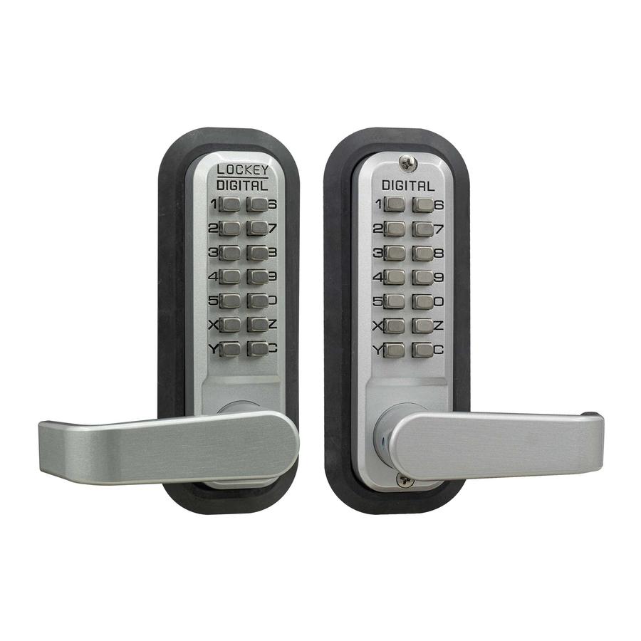
IMPORTANT INFORMATION ABOUT YOUR DIGITAL 2835
*
1. When the door is closed, the system locks automatically.
2. From the inside, unlock using the Lever Handle.
3. From the outside, unlock by pressing 'C' (CLEAR), followed
by your User Code.
4. The 2835 is equipped with a PASSAGE FUNCTION,
allowing you to leave the door unlocked.
-To enable the passage function:
Press 'C' (CLEAR), then 'Y' (PASSAGE), then enter User Code.
-To disable the passage function:
Press 'Y' (PASSAGE), followed by 'C' (CLEAR).
-To disable the passage function PERMANENTLY:
Remove the 'Y' (PASSAGE) tumbler, leaving that slot empty.
IMPORTANT: Always press and hold the 'C' Button when
removing and inserting Tumblers. Refer to 'How to Change
Code' instructions on reverse side.
Step 1: Change User Code/Combination (OPTIONAL)
To change user code/combination, see instructions on reverse side.
Step 2: Prep Door for Installation with Template
Place template (supplied) on door and fold along door's edge.
Mark holes for 2 3/8" or 2 3/4" backset. Drill holes as instructed.
Note: For pre-prepped 2 1/8" doors, you only need to drill top hole.
Step 3: Identify Door Handing
Right-Hand Doors – From exterior of door, hinges are on right-side (Fig. 1).
Left-Hand Doors – From exterior of door, hinges are on left-side (Fig. 2).
For Right-Hand Doors: Install Support Pin (#15) in position 'A'.
For Left-Hand Doors: Install the Support Pin (#15) in position 'B'.
Now, install/screw Hex Bolts (#17) into the top and bottom as shown.
Step 4: Install Lever Handles
Using Allen Wrench (#8), install levers to the inside and outside bodies.
Secure with set screws.
Note: Levers should point towards the door hinges.
Note: The 2835 is equipped with a built-in slip clutch lever handle to prevent
damage in the event of an attempted forced entry.
If lever handle is in position shown (far right), pull lever back to desired position.
Step 5: Adjust Latch (if necessary) and Install
Adjustable Latch (#14) is preset to 2 3/8" backset.
To adjust: Remove plastic plug, slide to 2 3/4", and replace plastic plug as shown (Fig. 5).
Insert Adjustable Latch (#14) into the door.
Secure with two (2) Wood Screws (#11).
Installation Instructions
*
No.
Part Name
1
Outside Body
2
Inside Body
3
Lever Handle
4
Rubber Trim Plate
5
Strike Plate
Mortised Striker
6
7
Spindle
8
Allen Wrench
9
Machine Screw M4 x 40mm
10
Machine Screw M4 x 30mm | 50mm
11
Wood Screw M4 x 16mm
Extra Code Tumblers (Red)
12
13
Extra Non-Code Tumblers (Blue)
14
Adjustable Latch 2 3/8" - 2 3/4"
15
Support Pin
16
Tweezers
17
Hex Bolts
Fig. 4
Continued on Reverse Side
Digital 2835 Lever
*with Passage Function
2835
1
1
2
2
1
1
1
1
2
1 | 1
4
2
3
1
1
1
2
15
Support Pin
Fig. 5
Fig. 3
RIGHT HAND
LEFT HAND
Slip Clutch
1. Remove Plastic Plug
2. Move/Slide to 2 3/4"
3. Replace Plastic Plug
Advertisement
Table of Contents

Related Manuals for LOCKEY 2835


Summary of Contents for LOCKEY 2835
- Page 1 Secure with set screws. Note: Levers should point towards the door hinges. Note: The 2835 is equipped with a built-in slip clutch lever handle to prevent damage in the event of an attempted forced entry. If lever handle is in position shown (far right), pull lever back to desired position.
- Page 2 If spindle extends less than 3/8” it may not engage the lock. If spindle extends more than 5/8”, it will cause the lock to bind. Step 7: Install the DIGITAL 2835 Fig. 7 Place the Rubber Trim Plate (#4) on the backside of the Outside Body (#1).
Need help?
Do you have a question about the 2835 and is the answer not in the manual?
Questions and answers