Table of Contents
Advertisement
Quick Links
Advertisement
Table of Contents

Related Manuals for Fastrax III


Summary of Contents for Fastrax III
-
Page 2: Warnings And Cautions
Warnings and Cautions WARNING TO REDUCE THE RISK OF FIRE OR ELECTRIC SHOCK, DO NOT EXPOSE THIS PRODUCT TO RAIN OR MOISTURE. DO NOT INSERT ANY METALLIC OBJECTS THROUGH THE VENTILATION GRILLS OR OTHER OPENINGS ON THE EQUIPMENT. CAUTION EXPLANATION OF GRAPHICAL SYMBOLS The lightning flash with arrowhead symbol, within an equilateral triangle, is intended to alert the user to the presence of uninsulated "dangerous voltage"... -
Page 3: Fcc Compliance
FCC COMPLIANCE STATEMENT FCC INFORMATION: THIS EQUIPMENT HAS BEEN TESTED AND FOUND TO COMPLY WITH THE LIMITS FOR A CLASS A DIGITAL DEVICE, PURSUANT TO PART 15 OF THE FCC RULES. THESE LIMITS ARE DESIGNED TO PROVIDE REASONABLE PROTECTION AGAINST HARMFUL INTERFERENCE WHEN THE EQUIPMENT IS OPERATED IN A COMMERCIAL ENVIRONMENT. -
Page 4: Important Safeguards
IMPORTANT SAFEGUARDS 1. Read these instructions. 2. Keep these instructions. 3. Heed all warnings. 4. Follow all instructions. 5. Do not use this apparatus near water. 6. Clean only with dry cloth. 7. Do not block any ventilation openings. Install in accordance with the manufacturer's instructions. -
Page 5: Table Of Contents
1.1 Features ............................... 1 Chapter 2 — Installation and Configuration ................3 2.1 Package Contents ..........................3 2.2 Basic Configuration of Fastrax III Dome Camera System ..............4 2.3 Setting Dome Camera Termination ...................... 5 2.4 Fail-safe Network ..........................6 2.5 Setting Dome Camera Address (ID) .................... - Page 6 3.13 Camera Menu type 2 ........................... 26 Focus Control ............................26 WB (White Balance) Control ....................... .27 AE Control ............................27 Line Lock Control ..........................28 3.14 Camera Menu type 3 ........................... 29 Focus Control ............................29 WB (White Balance) Control ........................ 30 AE Control ............................
-
Page 7: Chapter 1 - Introduction
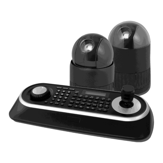
Chapter 1 — Introduction 1.1 Features The Fastrax III dome camera and the keyboard controller make up the building blocks for any surveillance/security system. Using multiple Keyboard Controllers and multiple dome cameras, no place is too large for monitoring. Extensible and flexible architecture facilitates remote control functions for a variety of external switching devices such as multiplexers and DVRs. - Page 8 Figure 1 – Typical System Configuration push bubble ring ass'y remove camera window screw push remove window assemble bubble ring ass'y Figure 2 –Assemble bubble ring ass’y (Optional) Note: It is recommended to remove camera window for improving picture quality when you use bubble ring ass’y.
-
Page 9: Chapter 2 - Installation And Configuration
………………………1 Fastrax III (Dome Camera) ………………………1(Optional) Bubble Ring ………………………1 Instruction Manual (This Document) ………………………3 Assembly Screws for Attaching Fastrax III ………………………3 Plastic Anchor ………………………1 10Pin Connector ………………………2 12Pin Connector CAUTION: Be sure to have caution labels (E version only) on both the body and the base of the camera. -
Page 10: Basic Configuration Of Fastrax Iii Dome Camera System
2.2 Basic Configuration of Fastrax III Dome Camera System Figure 4 – Basic installation diagram The dome camera must be installed by qualified service personnel in accordance with all local and federal electrical and building codes. The system should be installed according to... -
Page 11: Setting Dome Camera Termination
Figure 5 – Layout of Switches 2.3 Setting Dome Camera Termination The device which is connected at end of line, whether it be a dome camera or keyboard controller, must have the cable for communication terminated by setting the appropriate DIP switch. -
Page 12: Fail-Safe Network
2.4 Fail-safe Network When you control the dome by the other device not own keyboard, some error may be existed in the serial communication. The reason is caused by the other device without the fail-safe network. At this time, you solve the problem to set this DIP switch to ON of the nearest dome from the other device only. -
Page 13: Setting Dome Camera Address (Id)
2.5 Setting Dome Camera Address (ID) To prevent damage, each dome camera must have a unique address (ID). When installing multiple dome cameras using a multiplexer, it is suggested that the dome camera address match the multiplexer port number. If you want to set the address more than 999, you should contact the service provider. Example: Port 1 = Dome 1, Port 2 = Dome 2 …... -
Page 14: Setting Dome Camera Protocol
2.6 Setting Dome Camera Protocol If a dome camera is to be installed with a Fastrax keyboard controller, select the default protocol. Consult service personnel if a dome camera is installed with device other than a keyboard controller. UNCTION NTSC... -
Page 15: Connections
2.7 Connections • Connecting to the RS485/ 422 The dome camera can be controlled remotely by an external device or control system, such as a control keyboard, using RS485 half-duplex, RS422 full duplex or simplex serial communications signals. Connect Marked Tx+, Tx- to Tx+(Rx+) and Tx-(Rx-) of the RS485 control system. -
Page 16: Getting Started
2.8 Getting Started Once installed apply power to the dome camera. The dome camera will start a configuration sequence. PRESET TITLE AREA TITLE AF AE STATUS of FUNCTION FOCUS and AE UNDER RUNNING CAMERA TITLE EMPTY DATA INFORMATIO N DISPLAY CAMERA ID DOMEID:0001 PAN &... -
Page 17: Chapter 3 - Program And Operation
Chapter 3 — Program and Operation 3.1 Dome Camera Selection Before you program or operate a dome camera, you must select the dome camera by pressing the dome camera No. + CAM Example: Pressing 1 , 0 and CAM key sequentially will select dome camera 10. The selected dome camera ID will be displayed on the LCD monitor of the keyboard controller. -
Page 18: How To Control On-Screen Menu Utility
3.3 How to control the On-Screen Menu Utility Function Button Call the On-screen menu utility MENU Navigate through the menu items. Joystick up or down Joystick left or right Go into the sub-menu items. or IRIS Open Joystick left or right or Change value. - Page 19 SPEED : 1 - 13 step, the lower number means the slower speed. SCAN DIR : Set the scan direction, CCW(Counter Clock Wise), CW(Clock Wise) SWAP : Swap the start point for the end point. : Set the dwell time at the both end, 01 – 99 seconds DWELL 1.
-
Page 20: Preset
10. Set ―DWELL TIME‖. 11. Select Save and Exit and push the Joystick to the right or press IRIS Open. Press ESC or IRIS Close to exit the program without saving. Pressing the HOME key delete stored data at the angle field. To set the position using the preset position: a. - Page 21 PRESET SETUP NUMBER : 001 TITLE : --- CAMERA SET DWELL : --- SEC 12345678901234567890 00 █**----------------- 02 -------------------- 04 -------------------- 06 -------------------- NEXT PAGE SAVE AND EXIT(ESC TO CANCEL) - : blank preset position * : position has the preset █...
-
Page 22: Shortcut Preset Program
9. Select Save and Exit by pushing the Joystick to the right. Press ESC to exit the Preset menu without saving. NOTE: Press the HOME key at programmed preset position(*) to delete a programmed preset view. The position, which is marked with *, already has the preset view assigned. To review the stored preset, press PRST key on the *,The camera will show the stored preset scene. - Page 23 TOUR SETUP NUMBER TITLE SCAN TYPE NORMAL SPEED 5 STEP DWELL -- SEC 003 A08 --- --- --- --- --- --- --- --- --- --- --- --- --- --- P01 --- --- --- --- --- T02 --- --- --- --- --- --- --- --- --- --- --- --- --- --- --- --- --- --- --- SAVE AND EXIT(ESC TO CANCEL)
-
Page 24: Pattern
Example: Preset 001>002>003>004>005>006, Auto Scan 01 starts at preset 002, ends at preset 003, Auto Scan 02 starts at preset 005, ends at preset 006; Tour 001, 002, A01, 004, A02. 1 2 2~3 4 5~6, repeat ... -
Page 25: Alarm
4. Select Save and Exit and push the Joystick to the right. Press ESC to exit the program without saving. 5. To edit the title, follow the procedure of the auto scan above to edit titles. Press the HOME key at any programmed position to delete the pattern. NOTE: NOTE: If total recording time reaches 500 seconds, it will automatically stop for a moment. - Page 26 The RELAY OUT setup is helpful when the outdoor housing is used with the dome. Ex.) When you connect the relay output of the dome to the heater connector of the outdoor housing, the relay output can operate during the setting time only. RELAY OUT SETUP OUT1 : ALARM...
-
Page 27: Area Title
3.10 Area Title Enter a specific name on programmed angle between START and END. For the screen below, when the camera points at an angle between 124.3 (PAN), 30.7 (TILT) to 359.5 (PAN), 45.4 (TILT), ABC will be displayed on the screen. AREA TITLE SETUP NUMBER : 01... -
Page 28: Privacy Zone
3.11 Privacy Zone Hide up to 8 unwanted scenes in a camera. PRIVACY ZONE SETUP (CTRL KEY) TITLE METHOD 01 ABC BLOCK 02 DEF V.OFF ---- ---- ---- ---- ---- ---- SAVE AND EXIT(ESC TO CANCEL) 1. Place the cursor at the title field. 2. -
Page 29: Camera Menu Type 1
3.12 Camera Menu Type 1 NOTE: The features will vary depending on the camera module installed in your dome camera. CAMERA SETUP FOCUS CONTROL WB CONTROL AE CONTROL LINE LOCK CONTROL SHARPNESS : 09 DIGITAL ZOOM : OFF IMAGE FLIP : OFF PRESET FREEZE : OFF BRIGHT OFFSET : 0... -
Page 30: Wb (White Balance) Control
• WB (White Balance) CONTROL WB SETUP MODE R GAIN B GAIN SAVE AND EXIT(ESC TO CANCEL) MODE AUTO / INDOOR / OUTDOOR / ONE PUSH / ATW / MANUAL MANUAL Control of R and B gain AUTO Computes the white balance value output using color information from the entire screen automatically. -
Page 31: Line Lock Control
SLOW SHUTTER ON/OFF IRIS CLOSE / F28(26X,36X) / F22 / F19 / F16 / F14 / F11 / F9.6 / F8.0 / F6.8 / F5.6 / F4.8 / F4.0 / F3.4 / F2.8 / F2.4 / F2.0 / F1.6/F1.4(18X) 0 / 2 / 4 / 6 …… / 28 / -3 DB GAIN BRIGHT 0, 1,2, 3, 4 .. -
Page 32: Camera Menu Type 2
3.13 Camera Menu Type 2 NOTE: The menu features will vary depending on the camera module installed in your dome camera. CAMERA SETUP FOCUS CONTROL WB CONTROL AE CONTROL LINE LOCK CONTROL SHARPNESS : 007 DIGITAL ZOOM : OFF PRESET FREEZE : OFF SAVE AND EXIT(ESC TO CANCEL) SHARPNESS The higher the value, the more edges in the picture will be enhanced. -
Page 33: Wb (White Balance) Control
• WB (White Balance) CONTROL WB SETUP MODE :AWB R GAIN :071 B GAIN :069 SAVE AND EXIT(ESC TO CANCEL) MODE AWB / WAWB / INDOOR / OUTDOOR / MANUAL WAWB Wide range auto white balance mode. (2700 to 8500° K) RGAIN 0 ~ 255 BGAIN... -
Page 34: Line Lock Control
The Back Light operates in AUTO mode only. NOTE: For example, if you change the back light to ON, the camera will change AE mode to ―AUTO‖. The NIGHT SHOT option removes the IR cutoff filter of the camera and makes the camera sensitive to near infrared. -
Page 35: Camera Menu Type 3
3.14 Camera Menu Type 3 CAMERA SETUP FOCUS CONTROL WB CONTROL AE CONTROL LINE LOCK CONTROL SHARPNESS : AUTO DIGITAL ZOOM : OFF IMAGE FLIP : OFF PRESET FREEZE : OFF AGC LIMIT : 25 IMAGE STABLIZATION: OFF SAVE AND EXIT(ESC TO CANCEL) SHARPNESS The higher the value, the more edges in the picture will be enhanced (AUTO/0~31) -
Page 36: Wb (White Balance) Control
• WB (White Balance) CONTROL WB SETUP MODE AUTO R GAIN B GAIN SAVE AND EXIT(ESC TO CANCEL) MODE AUTO / MANUAL MANUAL Control of R and B gain AUTO Computes the white balance value output using color information from the entire screen automatically. (2800 to 8000 °K) RGAIN 0 ~ 255 BGAIN... - Page 37 IRIS OFFSET Set the overall brightness of a picture. (000-255, default :106) Increase the value to brighten the scene. Decrease the level to darken the scene. This is helpful when the scene is too bright or too dark. IRIS PEAK Set the effect of focusing peak, or how video peaks affect the overall picture brightness.
-
Page 38: Line Lock Control
• LINE LOCK CONTROL LINE LOCK SETUP MODE INTERNAL PHASE SAVE AND EXIT(ESC TO CANCEL) MODE INTERNAL / EXTERNAL PHASE Adjusts phase of picture with other cameras in EXTERNAL mode.( 0~255) 3.15 Camera - 26X MODEL Eclipse of the Lens: The eclipse phenomenon occurs with this model. -
Page 39: Dome Setup
3.16 Dome Setup CONFIGURATION MENU LANGUAGE : ENGLISH HOME FUNCTION SETUP OSD DISPLAY VIEW ANGLE SETUP INITIALIZE DATA ORIGIN OFFSET DOME RESET SYSTEM MENU SYSTEM INFORMATION SAVE AND EXIT(ESC TO CANCEL) • LANGUAGE SETUP LANGUAGE : Select the language you want. •... -
Page 40: Osd Display
• OSD DISPLAY OSD DISPLAY SETUP CAMERA TITLE : DOMEID VIEW DIRECTION : OFF DOME OSD : ON AREA TITLE : OFF PRESET TITLE : CONSTANT FOCUS EXPOSURE : ON OSD POSITION SETUP SAVE AND EXIT(ESC TO CANCEL) CAMERA TITLE : up to 6 characters. -
Page 41: View Angle Setup
• VIEW ANGLE SETUP VIEW ANGLE SETUP PANNING RANGE FLIP : 90 TILT OVER ANGLE : ON SAVE AND EXIT(ESC TO CANCEL) FLIP: OFF,90,100,110,120,AUTO(18X,26X,36X MODEL) : ON,OFF(22X MODEL) OFF: the dome camera moves until 90 vertically. 90, 100, 110, 120: allows the image to flip digitally when the camera moves over the setting angle vertically. -
Page 42: Initialize Data
PANNING RANGE When the dome camera is installed near a wall, panning range can be limited by user. PANNING RANGE SETUP (CTRL KEY) RIGHT LIMIT : 000.0 LEFT LIMIT : 000.0 ENABLE : OFF SWAP : OFF AUTO PAN : OFF SAVE AND EXIT(ESC TO CANCEL) 1. - Page 43 ERASE PROGRAMMED DATA Erase all stored data from the Flash-ROM of the selected dome camera. You will be asked to enter ON or OFF. If you desire to erase all data then select the Erase Run, otherwise press the ESC key to exit without erasing. The erased data includes all stored data (auto scan, presets, and tours….) except origin offset.
-
Page 44: Origin Offset
• ORIGIN OFFSET OFFSET SETUP (CTRL KEY) PAN OFFSET : 000.0 TILT OFFSET : 000.0 ENABLE : OFF SAVE AND EXIT(ESC TO CANCEL) This feature is useful to align a new dome camera exactly the same as the previously installed dome camera. Dome camera’s origin set and all data initialize option do not override offset values. - Page 45 MOTOR SETUP Motor Setup menu provides the pan and tilt speed of a camera. User can set the desired speed with twist the Joystick left or right. During operation, pressing 153 + ON will change the speed to the SLOW mode and pressing 153 + OFF will change the speed to the Normal mode.
-
Page 46: System Information
PASSWORD EDIT PASSWORD EDIT SETUP (CTRL KEY) INPUT PASSWORD PASSWORD : A B C D E F G H I J K L M N O P Q R S T U V W X Y Z 0 1 2 3 4 5 6 7 8 9 ( ) SAVE AND EXIT (ESC TO EXIT) You can change the password with 6-digit character in this menu. -
Page 47: Function Run
3.17 Function Run This Function Run menu allows you to execute the function when you use a keyboard or a DVR without the function keys (Preset, Pattern, Tour and scan). FUNCTION RUN SETUP (CTRL KEY) PRESET : --- PATTERN : --- TOUR : --- SCAN... -
Page 48: Motion Setup Type 1 (36X Model Only)
3.18 Motion Setup type 1(18x, 26x, 36x model) The motion detection function is available in the preset mode only. After you set the motion in any preset, when you call the preset with the motion, the motion detection operates. In the preset setup, you can set the motion setup as below. PRESET SETUP PRESET CAMERA SETUP NUMBER... -
Page 49: Motion Setup Type 2 (35X Model Only)
3.19 Motion Setup type 2 (35x model only) The motion detection function is available in the preset mode only. After you set the motion in any preset, when you call the preset with the motion, the motion detection operates. In the preset setup, you can set the motion setup as below. PRESET SETUP PRESET CAMERA SETUP NUMBER... -
Page 50: Appendix A - Specifications
Appendix A — Specifications 18x/22x/26x Optical Zoom Fastrax Dome System MODEL Camera Menu Type MODULE 1/4" Type Ex- 1/4" Type Super HAD CCD Type 1/4" Type Ex-view CCD view CCD Optical / Digital Zoom 18X/12X 26X/12X 22X/11X Resolution (NTSC/PAL) 540TVL... - Page 51 35x/36x Optical Zoom Fastrax Dome System MODEL Camera Menu Type MODULE CCD Type 1/4" Type Super HAD CCD 1/4" Type Ex-view CCD Optical / Digital Zoom 35X / 12X 36X / 12X Resolution (NTSC/PAL) 540TVL 540TVL Focal length 3.4mm~119mm 3.4mm~122.4mm 3.4mm-55.8°(H)
- Page 52 General Certification CE EMC, FCC CLASS A, CSA Electrical Input Voltage 18 to 30VAC; 24VAC nominal, 24VDC Power Requirement 24VAC/VDC 1A Power Consumption Maximum 20W Alarm Output 4 Normal relays 24VDC/1A Max. (selectable NC/NO) Alarm Input 8 Normal dry contact (selectable NC/NO) RS-485/422 baud rate: 2400~38.4k bps Control (default: 9600bps)
-
Page 53: Appendix B - Troubleshooting
Appendix B — Troubleshooting If problems occur, verify the installation of the camera with the instructions in this manual and with other operating equipment. Isolate the problem to the specific piece of equipment in the system and refer to the equipment manual for further information. Problem Possible Solution Verify that power is connected to all pieces of... -
Page 54: Appendix C - Glossary
Appendix C — Glossary Alarm Actions The assigned responses for the dome camera when inputs change from normal to abnormal states. The dome may run a Preset, Pattern, or have no assigned action for each of the four dome inputs. The dome may also send alarm states to the host controller for processing. See also Input and Normal Input State. -
Page 55: Line Lock
IR Mode A feature of the camera that permits manual or automatic switching between color and IR (black-and-white) operation. When IR mode is active, clearer images may be obtained under low-light conditions. Line Lock Allows you to phase lock the video with the AC power line. When line lock is enabled, it prevents vertical video rolling when switching multiple cameras to a single monitor. -
Page 56: Privacy Zones
Privacy Zones Masked areas of the dome camera's viewing area. These masks prevent operators of the surveillance system from viewing these designated zones. The Privacy Zones move in relation to the dome camera’s pan/tilt position. In addition, the apparent size of the Privacy Zone adjusts automatically as the lens zooms in or out. -
Page 57: Appendix D - Short Cut Key
Appendix D — Short Cut Key Short Cut Key Function PRST Pop up preset setup menu. TOUR Pop up Tour setup menu. PTRN Pop up Pattern setup menu. SCAN Pop up Auto Scan setup menu. NO.+ PGM Store the current view at the selected number. +PRST Short Cut Key Function... - Page 58 Short Cut Key Function Short Cut Key Function Go to the normal speed 153 + ON Go to the slow speed mode 153 + OFF mode 154 + ON Display System Information 155 + ON Flip the camera in the 180° area horizontally. 250 + PRESET Set the dome ID up to 3999 888 + ENTER...
- Page 59 - MEMO -...
Need help?
Do you have a question about the III and is the answer not in the manual?
Questions and answers