DeWalt DW708 Repair Manual
Hide thumbs
Also See for DW708:
- Instruction manual (54 pages) ,
- User manual (13 pages) ,
- Instruction manual (21 pages)
Advertisement
Advertisement
Table of Contents

Related Manuals for DeWalt DW708


Summary of Contents for DeWalt DW708
-
Page 1: Repair Information
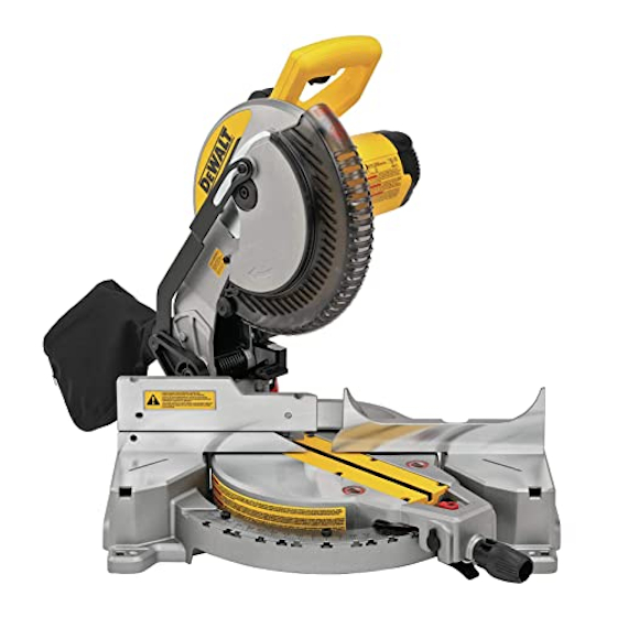
REPAIR INFORMATION DW708 MITRE SAW JUNE 1998... - Page 2 DW708 MITRE SAW - STRIDOWN PROCEDURE The machine consists of two main assemblies, the motor and guard (Head Assy.) and the rotary table and base (Table Assy.). These elements are connected by means of a bevel housing, that also supports the crosscut pull bars.
- Page 3 When re-assembling the motor, carefully position the motor cable in the correct position so that it cannot be trapped. Note that the two "lugs" on the bearing housing (94) fit into the two larger slots of the arm casting assy. (102) when putting the motor back onto this housing. (see drawing "A").
- Page 4 Take care not to lose or damage the two plastic shims (42) when removing the bracket part of the casting (102) from the bar and bracket (121). To re-assemble, make sure that the plastic shims (42) are fitted to the arm assembly casting (102).
- Page 5 ADJUSTMENT. Please refer to the Instruction manual for details on how to adjust the blade to the fence, the mitre pointer, mitre lock adjustment, and bevel adjustments. To adjust the bevel stop there are three bevel stop pins : *Top right (as you face the machine) is to adjust the blade 90 degrees to the fence. *Top left is to adjust the 45 degrees left bevel angle.
- Page 6 TYP. DW708 1998...
- Page 7 TYP. DW708 E12374 / 234444 03 / 06 / 98...
- Page 8 TYP. DW708 52 171 03 / 06 /98 E12498 / 234444...
- Page 9 TYP. DW708 WIRING DIAGRAM ELECTRICAL MAINS CORD CORD BLUE MAINS LEAD WHITE FIELD LEAD BROWN BLACK MAINS LEAD FIELD LEAD CAPACITOR BLACK CONNECTOR LEAD WHITE CONNECTOR LEAD BLACK CAPACITOR LEAD WHITE BLACK FIELD LEAD BLACK COLOUR KEY CAPACITOR FIELD LEAD...
- Page 10 DW708-----A 23/06/98 ------------------------------------------------------------------- ITEMDESCRIPTION PART NO. VARIANT DESCRIPTION SCREW 98094-55 SCREW 330019-19 SCREW 330019-20 SCREW 153778-00 SCREW 330045-05 SCREW 330045-13 SCREW 330045-14 SCREW 330045-15 SCREW 330045-18 SCREW.TEMP 330045-23 SCREW 330045-20 SCREW 145344-01 SCREW 153666-00 SCREW 153637-00 SCREW 153720-00 SCREW 150075-00...
- Page 11 DW708-----A 23/06/98 ------------------------------------------------------------------- ITEMDESCRIPTION PART NO. VARIANT DESCRIPTION SPRING 88165-00 SPRING 168507-00 SPRING 153596-01 BEARING 330003-09 BEARING 330003-48 BEARING 131790-00 BEARING 330003-47 BEARING 65786-00 DRIVE PULLEY 153554-00 PULLEY 153556-00 BELT 153555-00 GASKET 153560-00 LOCKING PIN 153561-00 153638-00 GEARCASE COVER 153754-00...
- Page 12 DW708-----A 23/06/98 ------------------------------------------------------------------- ITEMDESCRIPTION PART NO. VARIANT DESCRIPTION BRUSH & HOLDER 147097-06 M-XD BRUSH & HOLDER 147097-06 M-XE BRUSH HOLDER 147097-05 T-GB115V NAMEPLATE 384838-00 M-AT-BE-DE-ES-FR-GR-IT NAMEPLATE 384838-01 M-CH NAMEPLATE 384838-00 M-DK-FI-NO-SE-PT NAMEPLATE 384838-03 M-GB NAMEPLATE 384838-02 T-GB115V BAFFLE 146723-01 M-AT-BE-DE-ES-FR-GR-IT...
- Page 13 DW708-----A 23/06/98 ------------------------------------------------------------------- ITEMDESCRIPTION PART NO. VARIANT DESCRIPTION 102 ARM LINK 383331-01 T-GB115V 103 FOAM 153721-00 104 BELT COVER 153562-00 105 GUARD UPPER 153648-01 106 IDENTITY LABEL 149365-01 107 DUST EXTRACTOR 153567-00 108 TUBE UPPER 151949-00 109 GUARD LOWER 153602-02...
- Page 14 DW708-----A 23/06/98 ------------------------------------------------------------------- ITEMDESCRIPTION PART NO. VARIANT DESCRIPTION 163 WRENCH 153636-00 164 BRUSH SPRING 145323-02 165 BRUSH CAP 448084-01 166 WARNING LABEL 143861-00 167 WARNING LABEL 380179-00 M-AT-BE-DE-ES-FR-GR-IT 167 WARNING LABEL 148524-01 M-B1 167 WARNING LABEL 380179-00 M-CH 167 WARNING LABEL...
Need help?
Do you have a question about the DW708 and is the answer not in the manual?
Questions and answers
I have a DW 708 and I the alginment bolts when turned do not change the blade angle when turned
If the alignment bolts on your DeWalt DW708 do not change the blade angle when turned, first ensure the bevel adjustment is unlocked so the blade can move freely. If the blade still does not move, check for any obstructions or damage that may be preventing movement. Also verify that the bolts are not stripped or overtightened.
This answer is automatically generated