Table of Contents
Advertisement
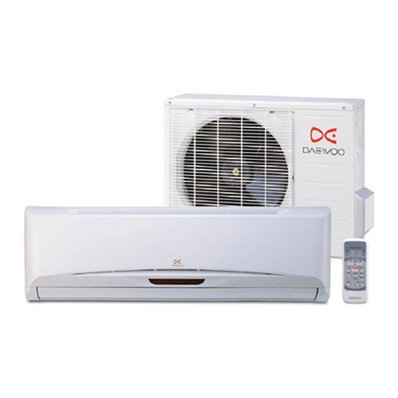
Service Manual
Split System
Air Conditioner
Model: DSB-075L
DSB-075LH
DSB-095L
DSB-095LH
DSB-125L
DSB-125LH
DSB-185L
DSB-185LH
Caution
: In this Manual, some parts can be changed for improving,
their performance without notice in the parts list. So, if you
need the latest parts information, please refer to PPL(Parts
Price List) in Service Information Center.
S/M NO : DSB075L001
MAY., 2006
Advertisement
Table of Contents


Need help?
Do you have a question about the DSB-075L and is the answer not in the manual?
Questions and answers