Table of Contents
Advertisement
Quick Links
QQ
3 7 63 1515 0
SERVICE MANUAL
Ver 1.2 2003. 11
TE
L 13942296513
CD player section
System
Compact disc digital audio system
Laser diode properties
Material: GaAlAs
Wave length: 780 nm
Emission duration: Continuous
Laser output: Less than 44.6 µW
(This output is the value measured at a distance
of about 200 mm from the objective lens surface
on the optical pick-up block with 7 mm
aperture.)
Spindle speed
200 r/min (rpm) to 500 r/min (rpm)
(CLV)
Number of channels
2
Frequency response
20 - 20 000 Hz +1/–2 dB
Wow and flutter
Below measurable limit
Radio section
Frequency range (CND, MX, E92)
FM: 87.5 - 108 MHz
AM: 530 - 1710 kHz
Frequency range (E15, SP)
FM: 87.5 - 108 MHz
AM: 531 - 1611 KHz
Antennas
FM: Telescopic antenna
AM: Built-in ferrite bar antenna
www
.
Sony Corporation
9-877-048-03
2003K16-1
Personal Audio Company
© 2003.11
Published by Sony Engineering Corporation
http://www.xiaoyu163.com
Cassette-corder section
Recording system
4-track 2 channel stereo
Fast winding time
Approx. 120 s (sec.) with Sony cassette C-60
Frequency response
TYPE I (normal): 80 - 10 000 Hz
General
Speaker
Full range: 10 cm dia., 6 ohms, cone type (2)
Outputs
Headphones jack (stereo minijack)
For 16 - 68 ohms impedance headphones
Power output
4.5 W + 4.5 W (at 6 ohms, 10% harmonic
distortion)
Power requirements
For CD radio cassette-corder:
120 V AC, 60Hz (CND, MX, E92)
230 V AC, 50Hz (SP)
115 - 127V/220 - 240V AC, 50/60Hz (E15)
9 V DC, 6 size D (R20) batteries
For remote control:
3 V DC, 2 size AA (R6) batteries
Power consumption
AC 25 W
Battery life
x
ao
u163
y
i
http://www.xiaoyu163.com
CFD-S700
2 9
8
Model Name Using Similar Mechanism CFD-S22/S32
CD
CD Mechanism Type
Section
Optical Pick-up Name
Model Name Using Similar Mechanism CFD-V5
TC
Section Tape Transport Mechanism Type
Q Q
SPECIFICATIONS
3
6 7
1 3
1 5
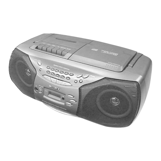
CD RADIO CASSETTE-CORDER
co
.
9 4
2 8
Canadian Model
E Model
KSM-213RDP
KSS-213R
MF-V5-117
0 5
8
2 9
9 4
2 8
For CD radio cassette-corder:
FM recording
Sony R20P: approx. 3.5 h
Sony alkaline LR20: approx. 10 h
Tape playback
Sony R20P: approx. 1.5 h
Sony alkaline LR20: approx. 5 h
CD playback
Sony R20P: approx. 1 h
Sony alkaline LR20: approx. 4 h
Dimensions
Approx. 420 × 159 × 284 mm (w/h/d)
× 6
× 11
5
3
1
(16
⁄
⁄
⁄
inches) (incl. projecting parts)
8
8
4
Mass
Approx. 4.3 kg (9 lb. 8 oz) (incl. batteries)
Supplied accessory
AC power cord (1)
Remote control (1)
Design and specifications are subject to change
without notice.
– Continued on next page –
m
9 9
9 9
1
Advertisement
Table of Contents

Related Manuals for Sony CFD-S700


Summary of Contents for Sony CFD-S700
-
Page 1: Specifications
4-track 2 channel stereo Sony R20P: approx. 3.5 h Laser diode properties Fast winding time Material: GaAlAs Approx. 120 s (sec.) with Sony cassette C-60 Sony alkaline LR20: approx. 10 h Wave length: 780 nm Frequency response Tape playback Emission duration: Continuous TYPE I (normal): 80 - 10 000 Hz Sony R20P: approx. -
Page 2: Table Of Contents
DIAGRAMMES SCHÉMATIQUES ET LA LISTE DES PIÈCES SONT — POWER SUPPLY Section — ........30 CRITIQUES POUR LA SÉCURITÉ DE FONCTIONNEMENT. NE REMPLACER CES COMPOSANTS QUE PAR DES PIÈSES SONY 7. EXPLODED VIEWS DONT LES NUMÉROS SONT DONNÉS DANS CE MANUEL OU 7-1. -
Page 3: Servicing Notes
CFD-S700 SECTION 1 SERVICING NOTES 3 7 63 1515 0 LASER DIODE AND FOCUS SEARCH OPERATION CHUCK PLATE JIG ON REPAIRING CHECK 1. Turn ON the POWER button and press FUNCTION button to On repairing CD section, playing a disc without the lid (CD), use CD position. -
Page 4: General
CFD-S700 SECTION 2 GENERAL 3 7 63 1515 0 This section is extracted from instruction manual. Location of controls Inserting a cassette Loading a CD With the side you want to play facing upward With the labeled side up Z PUSH OPEN/CLOSE VOLUME +,–... -
Page 5: Disassembly
CFD-S700 SECTION 3 DISASSEMBLY 3 7 63 1515 0 • The equipment can be removed using the following procedure. CABINET (FRONT) ASSY WIRES CONTROL (2) BOARD, CABINET (UPPER) ASSY INLET BOARD, CONTROL (3) BOARD, POWER BOARD CONTROL (1) BOARD... - Page 6 CFD-S700 3 7 63 1515 0 Note : Follow the disassembly procedure in the numerical order given. 3-1. Cabinet (Front) Assy 6 screw 9 cabinet (front) assy (BVTP 3x12) 7 connector (CNP323) lid (CD) 2 screw (BVTP 3x12) 8 flexible flat cable...
-
Page 7: Control (2) Board, Control (3) Board Control (1) Board
CFD-S700 3 7 63 1515 0 3-3. CONTROL (2) Board, CONTROL (3) Board, CONTROL (1) Board qd ten key button qg speaker (SP101) qs power button qk cabinet (front) sub assy qf four screws (+BVTP 3x10) 9 flexible flat cable (8 core) q;... - Page 8 CFD-S700 3 7 63 1515 0 3-5. Cabinet (Upper) Assy 4 screw (BVTP 3x12) 6 screw 3 holder assy, cassette (BVTP 3x12) 5 lid (CD) 1 two screws (BVTP 3x10) 2 three screws (BVTP 3x12) 7 handle 8 cabinet (upper) assy...
-
Page 9: Tape Mechanism Block (Mf-V5-117)
CFD-S700 3 7 63 1515 0 3-7. POWER AMP Board, MAIN Board 7 flexible flat cable qs MAIN board q; two screws (14 core)(CNP702) (BVTP 3x10) 9 BVTP 3x10 1 two screws (BVTP 3x10) 2 connector 6 connector (CNP303) -
Page 10: Cassette Holder Assy
CFD-S700 3 7 63 1515 0 3-9. Cassette Holder Assy 1 screw (BVTP 3x10) 2 DAMPER 4 cassette holder assy L 13942296513 3-10. PRE Board 1 screw (BVTT 2x6) 4 PRE board 3 Remove the solders. claw claw u163... -
Page 11: Belt, M801 (Capstan/Reel Motor), Hrp301 (Magnetic Head)
CFD-S700 3 7 63 1515 0 3-11. Belt, M801 (Capstan/Reel Motor), HRP301 (Magnetic Head) 6 HRP301 (magnetic head) 1 two screws (B 2.6 × 5) mechanism deck 5 claws 4 M801 3 belt (capstan/reel motor) L 13942296513 3-12. CD Board... -
Page 12: Cd Mechanism Deck (Ksm-213Rdp)
CFD-S700 3 7 63 1515 0 3-13. CD Mechanism Deck (KSM-213RDP) 1 two screws 2 two screws (PWH 2.6x10) (PWH 2.6x10) 3 CD mechanism deck (KSM-213RDP) L 13942296513 3-14. Optical Pick-up (KSS-213R) 2 two claws 3 cover, CD 5 two screws... -
Page 13: Mechanical Adjustments
CFD-S700 SECTION 4 SECTION 5 3 7 63 1515 0 MECHANICAL ADJUSTMENTS ELECTRICAL ADJUSTMENTS PRECAUTION TAPE SECTION 0 dB = 0.775 V 1. Clean the following parts with a denatured-alcohol-moistened swab : • Standard Output Level record/playback head pinch roller... -
Page 14: Tuner Section
CFD-S700 3 7 63 1515 0 TUNER SECTION 0 dB = 1 µV FM IF ADJUSTMENT • FM Section Adjust for a maximum reading on level meter. Setting: RADIO (BAND) button: FM 10.7 MHz FM RF signal generator FM FREQUENCY COVERAGE... -
Page 15: Q Q
CFD-S700 3 7 63 1515 0 Adjustment Location: CT1, L1 FM TRACKING ADJUSTMENT FM FREQUENCY COVERAGE ADJUSTMENT TP(JW1) – MAIN board (component side) – FM IF ADJUSTMENT FREQUENCY COVERAGE AM IF ADJUSTMENT ADJUSTMENT CT3, L3 TRACKING ADJUSTMENT L 13942296513 CD SECTION CD section adjustments are done automatically in this set. -
Page 16: Diagrams
CFD-S700 SECTION 6 DIAGRAMS 3 7 63 1515 0 6-1. IC Pin Description • IC802 uPD789477GC-A06-8BT (SYSTEM CONTROLLER) Pin No. Pin Name Pin Description 1, 2 — Not used. (Open) 3 – 5 VLC2 – 0 LCD drive voltage output 6 –... -
Page 17: Circuit Boards Location
CFD-S700 Ver 1.1 2003.03 3 7 6 3 1 5 1 5 0 Pin No. Pin Name Pin Description Main system oscillation output (4.19 MHz) System reset input ISS1 ISS1 output Not used. (Open) ISS2 ISS2 output Not used. (Open) -
Page 18: Block Diagram - Cd Section
CFD-S700 3 7 6 3 1 5 1 5 0 6-3. Block Diagram — CD Section — CD BOARD MAIN BOARD (1/2) CNP701 CD_IN_ L CNP702 (2/2) CNP804 (2/2) CNP806 (1/3) LCHO INTERPOLATION SLICE ERROR MUTE DIGITAL FIN2 EFMIN... -
Page 19: Block Diagram - Main Section
CFD-S700 3 7 6 3 1 5 1 5 0 6-4. Block Diagram — MAIN Section — PRE BOARD MAIN BOARD (2/2) POWER AMP BOARD R.RO R.IN R.LINE CD_IN_R CNP322 VOLUME/SOUND CONTROLLER POWER AMP REC/PB CNP301 CNP806 IC302 IC101... -
Page 20: Printed Wiring Board - Cd Section
CFD-S700 Ver 1.1 2003.03 3 7 6 3 1 5 1 5 0 6-5. Printed Wiring Board — CD Section — • Refer to page 17 for Circuit Boards Location. • : Uses unleaded solder. THIS NOTE IS COMMON FOR PRINTED WIRING BOARDS AND SCHEMATIC DIAGRAMS. -
Page 21: Schematic Diagram - Cd Section
CFD-S700 3 7 6 3 1 5 1 5 0 6-6. Schematic Diagram — CD Section — • Refer to page 20 for Common Note on Schematic Diagrams and page 31,32 for IC Block Diagrams. C727 1000p C726 1000p... -
Page 22: Printed Wiring Boards — Main Section
CFD-S700 3 7 6 3 1 5 1 5 0 • : Uses unleaded solder. 6-7. Printed Wiring Boards — MAIN Section — • Refer to page 17 for Circuit Boards Location and page 20 for Common Note on Printed Wiring Boards. -
Page 23: Schematic Diagram — Main Section (1/3)
CFD-S700 Ver 1.1 2003.03 3 7 6 3 1 5 1 5 0 6-8. Schematic Diagram— MAIN Section (1/3) — • Refer to page 20 for Common Note on Schematic Diagrams and page 32 for IC Block Diagrams. KV1520NT... -
Page 24: Schematic Diagram - Main Section (2/3)
CFD-S700 Ver 1.1 2003.03 3 7 6 3 1 5 1 5 0 6-9. Schematic Diagram — MAIN Section (2/3) — • Refer to page 20 for Common Note on Schematic Diagrams and page 33 for IC Block Diagrams. -
Page 25: Schematic Diagram - Main Section (3/3)
CFD-S700 3 7 6 3 1 5 1 5 0 6-10. Schematic Diagram — MAIN Section (3/3) — • Refer to page 20 for Common Note on Schematic Diagrams and page 33 for IC Block Diagrams. D101 R147 C130... -
Page 26: Printed Wiring Boards - Pre Board
CFD-S700 3 7 6 3 1 5 1 5 0 6-11. Printed Wiring Boards — PRE Board — • : Uses unleaded solder. 6-12. Schematic Diagram — PRE Board — • Refer to page 17 for Circuit Boards Location and page 20 for Common Note on Printed Wiring Boards. -
Page 27: Printed Wiring Boards - Control Section
CFD-S700 3 7 6 3 1 5 1 5 0 • : Uses unleaded solder. 6-13. Printed Wiring Boards — CONTROL Section — • Refer to page 17 for Circuit Boards Location and page 20 for Common Note on Printed Wiring Boards. -
Page 28: Schematic Diagrams - Control Section
CFD-S700 Ver 1.1 2003.03 3 7 6 3 1 5 1 5 0 6-14. Schematic Diagrams — CONTROL Section — • Refer to page 20 for Common Note on Schematic Diagrams. R467 R403 R470 R472 R473 2.2k 4.7k 2.2k... -
Page 29: Printed Wiring Boards - Power Supply Section
CFD-S700 Ver 1.1 2003.03 3 7 6 3 1 5 1 5 0 • : Uses unleaded solder. 6-15. Printed Wiring Boards — POWER SUPPLY Section — • Refer to page 17 for Circuit Boards Location and page 20 for Common Note on Printed Wiring Boards. -
Page 30: Schematic Diagrams Power Supply Section
CFD-S700 Ver 1.1 2003.03 3 7 6 3 1 5 1 5 0 6-16. Schematic Diagrams — POWER SUPPLY Section — • Refer to page 20 for Common Note on Schematic Diagrams. CNP902 CNP904 F902 F902 4A/125V : CND,E92,MX 3.15A/250V : E15,SP... - Page 31 CFD-S700 3 7 63 1515 0 • IC Block Diagrams IC701 LC78645NE-U (CD Board) 78 77 76 75 74 73 72 71 69 68 67 66 65 64 63 62 61 FIN1 – FIN2 – TIN1 TBAL – –...
- Page 32 CFD-S700 3 7 63 1515 0 IC702 BA5826FP-E2 (CD Board) IC1 TA2149N (MAIN Board) GND1 FM RF-OUT FM RF SP– D.BUFF VCC1 FM RF-IN SL– AM RF-IN D.BUFF AM LOW CUT LEVEL D.BUFF SHIFT MIX OUT FM OSC D.BUFF...
-
Page 33: Power Supply Section
CFD-S700 3 7 63 1515 0 IC803 BR24C01AF-WE2 (MAIN Board) IC302 M62429P (MAIN Board) VIN2 VOUT2 CLOCK 1K BIT EEPROM ARRAY VR 2 8BIT 7BIT VOL AMP 2 VREF LOGIC SLAVE • WORD CONTROL ADDRESS DATA ADDRESS 7BIT VOL AMP 1... -
Page 34: Exploded Views
A-3347-879-A CONTROL (2) BOARD, COMPLETE (EXCEPT E15) 3-224-379-51 LID, BATTERY CASE (MX) A-3663-904-A CONTROL (2) BOARD, COMPLETE (E15) 3-251-216-01 LID, BATTERY CASE (E92) 4-951-620-11 SCREW (2.6X10), +BVTP 3-038-018-01 EMBLEM, SONY 3-251-233-01 BUTTON, TEN KEY SP101 1-825-423-11 SPEAKER (10cm) (L-CH) u163... -
Page 35: Cabinet (Rear) Section
CFD-S700 Ver 1.1 2003.03 3 7 63 1515 0 7-2. Cabinet (Rear) Section supplied T901 L 13942296513 Ref. No. Part No. Description Remark Ref. No. Part No. Description Remark 3-251-229-01 CABINET, REAR * 55 A-3347-917-A BATTERY (1) BOARD, COMPLETE... -
Page 36: Cabinet (Upper) Section
CFD-S700 Ver 1.1 2003.03 3 7 63 1515 0 7-3. Cabinet (Upper) Section ANT1 S801 MF-V5-117 KSM-213RDP L 13942296513 LCD801 Ref. No. Part No. Description Remark Ref. No. Part No. Description Remark 3-923-736-01 COVER, CD * 101 A-3347-876-A MAIN BOARD, COMPLETE (CND,E92,MX) -
Page 37: Tape Mechanism Section -1
CFD-S700 3 7 63 1515 0 7-4. Tape Mechanism Section -1 (MF-V5-117) HRP301 HE301 L 13942296513 Ref. No. Part No. Description Remark Ref. No. Part No. Description Remark * 161 3-008-589-13 SLIDER (FF) 3-933-010-01 SPRING (S/P), TORSION * 162... -
Page 38: Tape Mechanism Section -2
CFD-S700 3 7 63 1515 0 7-5. Tape Mechanism Section -2 (MF-V5-117) S802 L 13942296513 M801 Ref. No. Part No. Description Remark Ref. No. Part No. Description Remark 3-933-020-11 BELT 3-933-029-01 LEVER, ERASING PREVENTION X-3377-877-3 FLYWHEEL ASSY 3-933-182-01 SPRING, CASSETTE... -
Page 39: Optical Pick-Up Section (Ksm-213Rdp)
CFD-S700 Ver 1.2 2003.11 3 7 63 1515 0 7-6. Optical Pick-up Section (KSM-213RDP) L 13942296513 supplied M702 M701 Ref. No. Part No. Description Remark Ref. No. Part No. Description Remark 0 251 8-820-161-02 DEVICE, OPTICAL KSS-213R/RP * 256... -
Page 40: Electrical Parts List
CFD-S700 Ver 1.1 2003.03 SECTION 8 BATTERY (1) ELECTRICAL PARTS LIST 3 7 63 1515 0 BATTERY (2) NOTE: • Abbreviation • Due to standardization, replacements in • COILS E92 : AC 120V area in E model the parts list may be different from the uH : µH... - Page 41 CFD-S700 Ver 1.1 2003.03 CONTROL (1) 3 7 63 1515 0 Ref. No. Part No. Description Remark Ref. No. Part No. Description Remark R707 1-216-797-11 METAL CHIP 1/10W R419 1-216-829-11 METAL CHIP 4.7K 1/10W R708 1-216-833-11 METAL CHIP 1/10W...
- Page 42 CFD-S700 Ver 1.1 2003.03 CONTROL (2) CONTROL (3) INLET MAIN 3 7 63 1515 0 Ref. No. Part No. Description Remark Ref. No. Part No. Description Remark A-3347-879-A CONTROL (2) BOARD, COMPLETE (EXCEPT E15) A-3347-884-A INLET BOARD, COMPLETE (included POWER Board)(E92,MX)
- Page 43 CFD-S700 Ver 1.1 2003.03 MAIN 3 7 63 1515 0 Ref. No. Part No. Description Remark Ref. No. Part No. Description Remark < CAPACITOR > C126 1-126-959-11 ELECT 0.47uF 20.00% 50V C131 1-126-964-11 ELECT 10uF 20.00% 50V 1-162-923-11 CERAMIC CHIP...
- Page 44 CFD-S700 Ver 1.1 2003.03 MAIN 3 7 63 1515 0 Ref. No. Part No. Description Remark Ref. No. Part No. Description Remark < FILTER > JC303 1-216-864-11 METAL CHIP 1/10W JC304 1-216-864-11 METAL CHIP 1/10W 1-795-035-11 FILTER, CERAMIC JC305...
- Page 45 CFD-S700 Ver 1.1 2003.03 MAIN 3 7 63 1515 0 Ref. No. Part No. Description Remark Ref. No. Part No. Description Remark 1-216-813-11 METAL CHIP 1/10W R327 1-216-833-11 METAL CHIP 1/10W R328 1-216-845-11 METAL CHIP 100K 1/10W 1-216-827-11 METAL CHIP 3.3K...
- Page 46 CFD-S700 Ver 1.1 2003.03 MAIN POWER POWER AMP 3 7 63 1515 0 Ref. No. Part No. Description Remark Ref. No. Part No. Description Remark C151 1-126-947-11 ELECT 47uF 20.00% 10V R850 1-216-821-11 METAL CHIP 1/10W C152 1-162-964-11 CERAMIC CHIP 0.001uF...
- Page 47 CFD-S700 Ver 1.2 2003.11 SELECTION 3 7 63 1515 0 Ref. No. Part No. Description Remark Ref. No. Part No. Description Remark A-3062-297-A PRE BOARD, COMPLETE R304 1-216-821-11 METAL CHIP 1/10W ******************** R305 1-216-811-11 METAL CHIP 1/10W R306 1-218-867-11 METAL CHIP 6.8K...
- Page 48 CFD-S700 3 7 63 1515 0 REVISION HISTORY Clicking the version allows you to jump to the revised page. Also, clicking the version at the upper right on the revised page allows you to jump to the next revised page.
Need help?
Do you have a question about the CFD-S700 and is the answer not in the manual?
Questions and answers