Roland Texart XT-640 Setup Manual
Hide thumbs
Also See for Texart XT-640:
- Setup & maintenance manual (77 pages) ,
- Maintenance (2 pages) ,
- Product manual (48 pages)
Table of Contents
Advertisement
Thank you very much for purchasing this product.
To ensure correct and safe usage with a full understanding of this product's performance, please be sure to read
through this manual completely and store it in a safe location.
Unauthorized copying or transferral, in whole or in part, of this manual is prohibited.
The specifications of this product and the contents of this manual are subject to change without notice.
This manual and the product have been prepared and tested as much as possible. If you find any misprints or
errors, please inform Roland DG Corp.
Roland DG Corp. assumes no responsibility for any direct or indirect loss or damage that may occur through use
of this product, regardless of any failure to perform on the part of this product.
Roland DG Corp. assumes no responsibility for any direct or indirect loss or damage that may occur with respect
to any article made using this product.
Setup Guide
Advertisement
Table of Contents

Related Manuals for Roland Texart XT-640


Summary of Contents for Roland Texart XT-640
-
Page 1: Setup Guide
Roland DG Corp. Roland DG Corp. assumes no responsibility for any direct or indirect loss or damage that may occur through use of this product, regardless of any failure to perform on the part of this product. -
Page 3: Table Of Contents
Step 2: Make the Network Settings on the Printer ................37 Step 3: Make the Port Settings for the Software RIP ................39 Company names and product names are trademarks or registered trademarks of their respective holders. Copyright © 2015 Roland DG Corporation http://www.rolanddg.com/... -
Page 5: Installation Environment
1. Installation Environment Deciding On an Installation Site Install the machine in a quiet, stable location offering good operating conditions. An unsuitable location can cause accidents, fire, faulty operation, or breakdown. WARNING Install the machine in a location that is level, stable, and able to bear the weight of the machine. -
Page 6: Temperature And Humidity
1. Installation Environment Temperature and Humidity Maintain the specified temperature and humidity even when the machine is not in use. Failure to do so may result in malfunction. During operation: Temperature 18 to 25°C (64 to 77°F), humidity: 35 to 65%RH (no condensation) During non-operation: Temperature 15 to 30°C (59 to 86°F), humidity: 20 to 80%RH (no condensation) Installation Space The space shown in the figure is required in order to use this machine. -
Page 7: Included Items
2. Included Items The following items are included with the machine. Make sure they are all present before proceeding. Printer Unit Arms Stand legs Power cord (1) Casters (2) (1 each for right and left) (1 each for right and left) Stand stay (1) Shafts (2) Paper tube (1) -
Page 8: Roland Ink System
Spanner maintenance guide (1) Software RIP (1) wrench (1) * Not required when using four colors (cyan, magenta, yellow, and black). Roland Ink System Ink pouch holder (1) Subtank guard (1) Subtank cartridges (8) Ink tube covers (bottom) Ink tube cover (top; 1) -
Page 9: About The Symbols
3. About the Symbols The meanings of the symbols used in this document are as follows. This symbol indicates instructions that must be followed in relation to op- eration. Always follow these instructions to prevent accidents and damage due to misoperation. This symbol indicates things that must be checked visually in relation to operation. -
Page 10: Assembly And Ink Filling
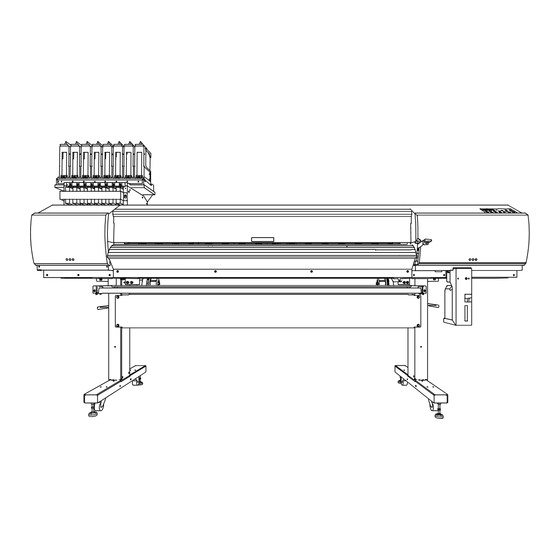
4. Assembly and Ink Filling Checks before Operations CAUTION Unpacking and installation must be carried out by six or more people. Failure to observe this instruction may cause the machine to fall over, resulting in injury. Completed Drawing Necessary Tools Commercially Included items available item... -
Page 11: Step 1: Assembling The Stand
4. Assembly and Ink Filling Step 1: Assembling the Stand Procedure Place the stand leg with the tabletop plate facing down, and then place the caster on top of the stand leg. Place the caster on the stand leg so that the surface without a slit faces the attachment surface of the stand leg. Caster Slit Attachment surface... - Page 12 4. Assembly and Ink Filling Press the caster in the direction indicated by the arrow, and then tighten the bolts fully in the four locations in the order of Use the pipe for the two locations indicated by Pipe Tighten fully Bolts: 4 Insert the stand leg fixing plate into the caster slit.
- Page 13 4. Assembly and Ink Filling Tighten the bolts in the order of to secure the plate. Tighten fully Bolts: 4 Assemble the opposing leg by following the same procedure from step to step Position the stand legs parallel to each other and separated by approximately 1,800 mm (70.9 in.).
- Page 14 4. Assembly and Ink Filling Adjust the installation width of the stand legs to match the stand stay attachment holes with the stand leg attachment positions. Stand stay Position the surface with attachment holes toward the tabletop plate. Stand stay at- tachment part Tabletop plate...
- Page 15 4. Assembly and Ink Filling Tighten the bolts fully in the four locations on the side and then in the four locations on the top in the order of Tighten fully Make sure these are parallel. Make sure these are parallel.
-
Page 16: Step 2: Attaching The Machine
4. Assembly and Ink Filling Step 2: Attaching the Machine Procedure Place the machine on the stand. Arrange the stand so that the bent side of the tabletop plates ( ) are to the back. Tighten the bolts in the two locations on the back and then in the two locations on the bottom in the order of to secure the machine to the stand First tighten the bolts temporarily in the order of... -
Page 17: Step 3: Installing The Media Holders
4. Assembly and Ink Filling Step 3: Installing the Media Holders Attach the arms. Temporarily tighten two bolts on the stand leg. Tighten the bolts until they protrude by approximately 10 mm (0.4 in.). Pass the temporarily tightened bolts through the slotted attachment holes of the arm. The left arm and right arm are shaped differently, so check the shape when attaching the arm to the leg. - Page 18 4. Assembly and Ink Filling While pressing the arm's bent surface onto the stand leg, temporarily tighten the bolts. Fully tighten the bolts in the order of (stand rear) and then (stand side). Tighten fully Attach the opposing arm to the other leg by following the same procedure from step ...
- Page 19 4. Assembly and Ink Filling Attach the media holder adjuster to the right arm as seen from the rear of the machine. Pass the protrusions of the media holder adjuster ( ) through the notches on the arm ( ), and then temporarily tighten the bolts so that the adjustment stay does not fall off.
- Page 20 4. Assembly and Ink Filling Attach the media holders. Place the shafts on the arms. First insert the shafts into the holes on the right side as seen from the rear of the machine, and then place the shafts into the holes on the left side. ...
- Page 21 4. Assembly and Ink Filling Move the right media holder to the right side of the shaft, and then loosely tighten the retaining screw. Retaining screw In the same manner, pass the shaft through the left media holder, and then loosely tighten the retaining screw.
-
Page 22: Step 4: Installing The Feed Adjusters
4. Assembly and Ink Filling Use the shaft clamps to secure the shafts in place. To ensure the media holders do not get caught in the shaft clamps, do not place the media holders too close to the edges. Step 4: Installing the Feed Adjusters Procedure ... - Page 23 4. Assembly and Ink Filling Tighten the bolts in 2 locations to secure the feed adjuster stays. Attach the bolts removed in step together with the feed adjuster stays to the machine. (Do not use the washers removed in step Tighten fully Bolts: 4 Tighten the bolts in 4 locations to secure the feed adjusters.
-
Page 24: Step 5: Installing The Drain Bottle
4. Assembly and Ink Filling Step 5: Installing the Drain Bottle Procedure Remove the drain tube cover ( Secure the bottle stand in place ( Use the bolts that were securing the drain tube cover in place to secure the bottle stand in place. Remove the drain bottle cap. - Page 25 4. Assembly and Ink Filling Secure the drain tube cover that you removed in step in place at the position indi- cated in the figure. Use the screw already inserted into the machine to secure in place just the right side of the drain tube cover. Secure the right side only.
-
Page 26: Step 6: Removing The Retainers
4. Assembly and Ink Filling Step 6: Removing the Retainers Make sure to remove the retainers. If it remains on the machine, faulty operation or breakdown may occur when the power is switched on. Store the retainers because they are needed again when transporting the machine. Procedure ... -
Page 27: Step 7: Installing The Ink System
Leave this work to a suitably qualified worker. This procedure includes work near sources of electrical danger and complex assembly work. Incorrect work may result in injury and mechanical malfunction. Items used in this procedure Roland Ink System 1 set Tube caps Printer unit included items... - Page 28 4. Assembly and Ink Filling Connect both the power cord and the Ethernet cable (commercially available). Use a power plug adapter if the electrical outlet is a two-prong outlet. WARNING Connect the machine to an electrical outlet that complies with this ma- chine’s ratings (for voltage, frequency, and current).
- Page 29 4. Assembly and Ink Filling Turn nut A until the base of the stand adjuster touches the floor. Perform the same operation for the other stand adjusters. Nut A Stand adjuster When each adjuster is touching the floor, use a spanner to rotate nut A through one turn. Turn nut B until it comes in contact with nut C.
- Page 30 4. Assembly and Ink Filling Close the front cover. Make the initial settings. Switch on the main power switch. Hold down and press the sub power switch.
-
Page 31: Step 9: Ink Filling
4. Assembly and Ink Filling When the screen on the left is displayed, select the desired language, and then press Press to select the desired length unit, and then press Select the desired temperature unit in the same way, and then press Step 9: Ink Filling Select the ink type. - Page 32 4. Assembly and Ink Filling Apply the cleaning liquid. When the screen on the left is displayed, dip the cleaning stick in the cleaning liquid, and then apply the liquid to the parts shown in the figure. Application area * Cleaning liquid will be supplied by the service technician during installation.
- Page 33 4. Assembly and Ink Filling Fill the machine with ink. Verify that the screen on the left is displayed, and pull the ink pouch holder toward the front of the machine. Press If no subtank or the subtank guard is attached, the following screen will be displayed. Insert a subtank for every slot whose number is flashing.
- Page 34 In the event you install an ink pouch of the wrong color, contact your authorized Roland DG Corp. dealer. Never touch the area around the ink filling port. Touching this area accidentally may force air into the ink path and cause a malfunction.
- Page 35 4. Assembly and Ink Filling When the screen on the left is displayed, raise all the ink pouch holders. Hold here Do not let go off the ink pouch holders when lifting them. Raise the holders slowly until they click firmly into place. Ink will leak if the ink pouch holder is not returned to the correct position. ...
- Page 36 After this, the next step is to adjust the feed adjusters and the media holder adjusters. This procedure will be performed by a Roland DG service technician, so leave it up to them. * For information on how to install the take-up system, refer to the take-up system user’s manual.
-
Page 37: Network Settings
5. Network Settings Memo The examples used in the procedures for configuring the settings described in this section as- sume you’re using one computer and one machine. The settings used in this section are merely example settings. The procedures and setting values described here may not be suitable for all operating environments. - Page 38 5. Network Settings Click [Properties]. The [Ethernet Properties] dialog box appears. (On Windows 7, the [Local Area Connection Status] dialog box appears.) If the [User Account Control] dialog box appears, click [Continue]. Select [Internet Protocol Version 4 (TCP/ IPv4)], and then click [Properties].
-
Page 39: Step 2: Make The Network Settings On The Printer
5. Network Settings Select [Use the following IP address]. Enter the information as shown below, and then click [OK]. [IP address]: 192.168.0.XXX [Subnet mask]: 255.255.255.0 Here, "XXX" can be any number from 1 to 254. Howev- er, be sure to specify a number that is different from the numbers used for other computers and devices. -
Page 40: Set The Subnet Mask
5. Network Settings When you have finished making the setting, press Press The screen returns to the screen in the figure. Set the subnet mask. Press Press twice. Press to select the address number. [SUBNET MASK]: 255.255.255.000 For the subnet mask, make the setting the same value as the one used by the computer. -
Page 41: Step 3: Make The Port Settings For The Software Rip
5. Network Settings Press Repeat to set the gateway address. When you have finished making the setting, press Press to go back to the original screen. Step 3: Make the Port Settings for the Software RIP Refer to the documentation for the software RIP you are using, and set the software RIP output destination. - Page 44 R1-151111...
Need help?
Do you have a question about the Texart XT-640 and is the answer not in the manual?
Questions and answers