
Related Manuals for Toshiba RAS-24N3KV2-A


Summary of Contents for Toshiba RAS-24N3KV2-A
-
Page 1: Service Manual
FILE NO. SVM-13004 SERVICE MANUAL AIR-CONDITIONER SPLIT TYPE Indoor Unit Outdoor Unit <High Wall, Heat Pump Type> <Heat Pump Type> RAS-24N3KV2-A RAS-24N3AV2-A R410A February,2013... -
Page 2: Table Of Contents
FILE NO. SVM-13004 CONTENTS 1. SAFETY PRECAUTIONS ................2 2. SPECIFICATIONS ..................5 3. REFRIGERANT R410A ................7 4. CONSTRUCTION VIEWS ................ 15 5. WIRING DIAGRAM .................. 17 6. SPECIFICATIONS OF ELECTRICAL PARTS ......... 19 7. REFRIGERANT CYCLE DIAGRAM ............20 8. -
Page 3: Safety Precautions
FILE NO. SVM-13004 1. PRECAUTIONS FOR SAFETY • Before insallation, please read these precautions for safety carefully. • Be sure to follow the precautions provided here to avoid safety risks. The symbols and their meanings are shown below. WARNING : It indicates that incorrect use of this unit may cause severe injury or death. CAUTION : It indicates that incorrect use of this unit may cause personal injury (*1), or property damage (*2). - Page 4 FILE NO. SVM-13004 WARNING • Never modify this unit by removing any of the safety guards or bypassing any of the safety interlock switches. • Installation work must be requested from the supplying retail dealership or professional vendors. Self-installation may cause water leakage, electrical shock, or fire as a result of improper installation. •...
- Page 5 FILE NO. SVM-13004 CAUTION CAUTION • Exposure of unit to waer or other moisture before installation could result in electric shock. Do not store it in a wet basement or expose to rain or water. • After unpacking the unit, examine it carefully for possible damage. •...
-
Page 6: Specifications
Outdoor (Cooling/Heating) (°C) Accessory Indoor unit Installation plate Wireless remote controller Batteries Remote controller holder Toshiba New IAQ filte (Long) 6(∅4x25L) Mounting screw Remote controller holder 2(∅3.1x16L), ( 3.1x25L) ∅ Pan head wood screw − Plasma air purifier Installation manual... -
Page 7: Operation Characteristic Curve
FILE NO. SVM-13004 2-2. Operation Characteristic Curve <Cooling> <Heating> Conditions Conditions Indoor : DB 27 C/WB 19 Indoor : DB 20 C/WB 15 Outdoor : DB 35 C/WB 24 Outdoor : DB 7 C/WB 6 Indoor Air Flow : High Indoor Air Flow : High Pipe Length : 7.5m Pipe Length : 7.5m... -
Page 8: Refrigerant R410A
FILE NO. SVM-13004 3. REFRIGERANT R410A This air conditioner adopts the new refrigerant HFC 6. When an air conditioning system charged with a (R410A) which does not damage the ozone layer. large volume of refrigerant is installed in a small room, it is necessary to exercise care so that, The working pressure of the new refrigerant R410A even when refrigerant leaks, its concentration... - Page 9 FILE NO. SVM-13004 Table 3-2-1 Thicknesses of annealed copper pipes Thickness (mm) Nominal diameter (in.) Outer diameter (mm) R410A 6.35 0.80 0.80 9.52 0.80 0.80 12.70 0.80 0.80 15.88 1.00 1.00 2. Joints For copper pipes, flare joints or socket joints are used. Prior to use, be sure to remove all contaminants. a) Flare Joints Flare joints used to connect the copper pipes cannot be used for pipings whose outer diameter exceeds 20 mm.
- Page 10 FILE NO. SVM-13004 d) Flare Processing Make certain that a clamp bar and copper pipe have been cleaned. ØD By means of the clamp bar, perform the flare processing correctly. Use either a flare tool for R410A or conven- tional flare tool. Flare processing dimensions differ according to the type of flare tool.
- Page 11 FILE NO. SVM-13004 Table 3-2-6 Flare and flare nut dimensions for R22 Dimension (mm) Nominal Outer diameter Thickness Flare nut width diameter (in.) (mm) (mm) (mm) 6.35 9.52 13.0 13.5 12.70 16.0 16.2 12.9 15.88 19.0 19.7 16.0 Fig. 3-2-2 Relations between flare nut and flare seal surface 2.
- Page 12 FILE NO. SVM-13004 3-3. Tools 3-3-1. Required Tools The service port diameter of packed valve of the outdoor unit in the air-water heat pump using R410A is changed to prevent mixing of other refrigerant. To reinforce the pressure-resisting strength, flare processing dimensions and opposite side dimension of flare nut (For Ø12.7 copper pipe) of the refrigerant piping are lengthened.
-
Page 13: Recharging Of Refrigerant
FILE NO. SVM-13004 3-4. Recharging of Refrigerant When it is necessary to recharge refrigerant, charge the specified amount of new refrigerant according to the following steps. Recover the refrigerant, and check no refrigerant remains in the equipment. When the compound gauge’s pointer has indicated –0.1 Mpa (–76 cmHg), place the handle Low in the fully closed position, and turn off the vacuum pump’s power switch. -
Page 14: Brazing Of Pipes
FILE NO. SVM-13004 1. Be sure to make setting so that liquid can be charged. 2. When using a cylinder equipped with a siphon, liquid can be charged without turning it upside down. It is necessary for charging refrigerant under condition of liquid because R410A is mixed type of refrigerant. Accordingly, when charging refrigerant from the refrigerant cylinder to the equipment, charge it turning the cylinder upside down if cylinder is not equipped with siphon. - Page 15 FILE NO. SVM-13004 3-5-3. Brazing 2. Characteristics required for flux • Activated temperature of flux coincides with As brazing work requires sophisticated techniques, the brazing temperature. experiences based upon a theoretical knowledge, it must be performed by a person qualified. •...
-
Page 16: Construction Views
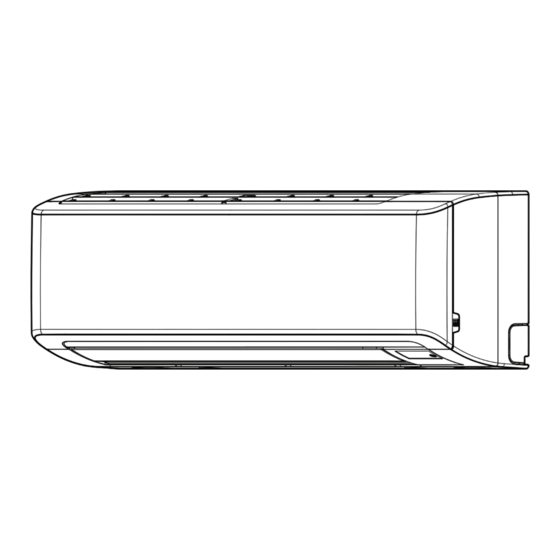
FILE NO. SVM-13004 4. CONSTRUCTION VIEWS 4-1. Indoor Unit Heat exchanger Grille Inlet Air Inlet Air filter 1050 Front Panel Air outlet Knock out system Knock out system Wireless remote controller 17.5 Remote controller holder Drain hose (0.5m) Hanger Hanger Connecting pipe (0.39m) Connecting pipe (0.49m) 12.70) - Page 17 FILE NO. SVM-13004 4-2. Outdoor Unit – 16 –...
-
Page 18: Wiring Diagram
FILE NO. SVM-13004 5. WIRING DIAGRAM 5-1. Indoor Unit 1∅ 220−240 ~50Hz CN11 (BLK) – 17 –... - Page 19 FILE NO. SVM-13004 5-2. Outdoor Unit (From Main Line) – 18 –...
-
Page 20: Specifications Of Electrical Parts
FILE NO. SVM-13004 6. SPECIFICATIONS OF ELECTRICAL PARTS 6-1. Indoor Unit Parts name Type Specifications Fan motor (for indoor) ICF-340-30-2Β DC340V, 30W Room temp. sensor (TA-sensor) ( — ) 10kΩ at 25°C Heat exchanger temp. sensor (TC-sensor) ( — ) 10kΩ... -
Page 21: Refrigerant Cycle Diagram
FILE NO. SVM-13004 7. REFRIGERANT CYCLE DIAGRAM 7-1. Refrigerant Cycle Diagram T1 Temp. measurement INDOOR UNIT Indoor heat exchanger Cross flow fan Max. : 30m Min. : 2m Chargeless : 20m Pressure measurement Deoxidized copper pipe Charge : 30g/m Gauge attaching port Outer dia. - Page 22 FILE NO. SVM-13004 7-2. Operation Data <Cooling> Tempeature Standard Heat exchanger Indoor Outdoor Compressor condition(°C) pressure pipe temp. fan mode fan mode revolution Indoor Outdoor P (MPa) T1 (°C) T2 (°C) (rps) 27/19 35/24 0.8 to 0.9 7.0 to 9.0 46 to 47 High High...
-
Page 23: Control Block Diagram
FILE NO. SVM-13004 8. CONTROL BLOCK DIAGRAM 8-1. Indoor Unit Heat Exchanger Sensor (TCJ) Indoor Unit Control Unit Heat Exchanger Sensor (Tc) Louver Functions Motor • Cold draft preventing Function Room Temperature Sensor (Ta) • 3-minute Delay at Restart Louver Motor for Compressor Drive Control Infrared Rays Signal Receiver... - Page 24 FILE NO. SVM-13004 8-2. Outdoor Unit (Inverter Assembly) – 23 –...
-
Page 25: Operation Description
FILE NO. SVM-13004 9. OPERATION DESCRIPTION 9-1. Outline of Air Conditioner Control • Detection of inverter input current and current release operation This air conditioner is a capacity-variable type air • Over-current detection and prevention operation conditioner, which uses DC motor for the indoor fan to IGBT module (Compressor stop function) motor and the outdoor fan motor. - Page 26 FILE NO. SVM-13004 9-2. Operation Description 9-2. 1. Basic operation ......................26 1. Operation control ....................26 2. Cooling/Heating operation ..................27 3. AUTO operation...................... 27 4. DRY operation ......................27 2. Indoor fan motor control ....................28 3. Outdoor fan motor control ................... 30 4.
-
Page 27: Basic Operation
FILE NO. SVM-13004 Item Operation flow and applicable data, etc. Description 1. Basic 1. Operation control operation Receiving the user’s operation condition setup, the operation statuses of indoor/outdoor units are controlled. 1) The operation conditions are selected by the remote controller as shown in the below. 2) A signal is sent by ON button of the remote controller. -
Page 28: Cooling/Heating Operation
FILE NO. SVM-13004 Item Operation flow and applicable data, etc. Description 1. Basic 2. Cooling/Heating operation operation The operations are performed in the following parts by controls according to cooling/heating conditions. 1) Receiving the operation ON signal of the remote controller, the cooling or heating operation signal starts being transferred from the indoor controller to the outdoor unit. -
Page 29: Indoor Fan Motor Control
FILE NO. SVM-13004 Item Operation flow and applicable data, etc. Description 2. Indoor fan <In cooling operation> motor control ∗ ∗ ∗ ∗ ∗ ∗ ∗ ∗ Symbols (This operation controls the fan speed at indoor unit side.) The indoor fan (cross flow fan) is operated by the phase- UH: Ultra High control induction motor. - Page 30 FILE NO. SVM-13004 Item Operation flow and applicable data, etc. Description 2. Indoor fan <In heating operation> 1) When setting the fan speed to L, motor control L+, M, M+ or H on the remote controller, the operation is per- formed with the constant speed HEAT ON shown in Fig.
-
Page 31: Outdoor Fan Motor Control
FILE NO. SVM-13004 Item Operation flow and applicable data,etc Description 3. Outdoor fan 3-1) Cooling fan control control Revolution frequency allocation of fan taps [rpm] The outdoor fan is controlled by TL sensor, TO sensor and the operation frequency. The outdoor fan is controlled by every 1 tap of DC fan control (15 taps). - Page 32 FILE NO. SVM-13004 Item Operation flow and applicable data,etc Description 3. Outdoor fan 3-2) Heating fan control control The outdoor fan is controlled by TE sensor, TO sensor and the operation frequency. (Control from minimum W1 to maximum (according to the following table)) ‚...
-
Page 33: Capacity Control
FILE NO. SVM-13004 Item Operation flow and applicable data, etc. Description 4. Capacity The cooling or heating capacity depending on the load is 1) The difference between set control adjusted. temperature on remote controller (Ts) and room temperature (Ta) According to difference between the setup value of tempera- is calculated. -
Page 34: Coil Heating Control
FILE NO. SVM-13004 Item Operation flow and applicable data,etc Description 5. Coil heating 1) This control function heats the compressor by turning on the stopped compressor instead of a case control heater. It purposes to prevent stagnation of the refrigerant inside of the compressor. 2) As usual, turn on power of the compressor for the specified time before a test run after installation;... -
Page 35: Current Release Control
FILE NO. SVM-13004 Item Operation flow and applicable data, etc. Description 7. Current This function prevents troubles on the electronic parts of the 1) The input current of the outdoor release control compressor driving inverter. unit is detected in the inverter section of the outdoor unit. -
Page 36: Release Protective Control By Temperature Of Indoor Heat Exchanger
FILE NO. SVM-13004 Item Operation flow and applicable data, etc. Description 9. Release protective <In cooling/dry operation> 1) When temperature of the indoor control by heat exchanger drops below 5°C, (Prevent-freezing control for indoor heat exchanger) temperature of the compressor speed is re- In cooling/dry operation, the sensor of indoor heat indoor heat duced. -
Page 37: Defrost Control (Only In Heating Operation)
FILE NO. SVM-13004 Operation flow and applicable data, etc. Description Item 1) In heating operation, defrost operation is performed when TE sensor satisfies any condition 10. Detrost control (only in heating in A zone to D zone. operation) 2) During defrosting operation, it finishes if TE sensor continued 12°C or higher for 3 seconds or continued 7°C ≤... -
Page 38: Louver Control
FILE NO. SVM-13004 Item Operation flow and applicable data, etc. Description 11. Louver control This function controls the air direction of the indoor unit. 1) Louver • The position is automatically controlled according to the operation position mode (COOL/HEAT). • The set louver position is stored in memory by the microcomputer, and the louver returns to the stored position when the next operation is performed. -
Page 39: Eco Operation
FILE NO. SVM-13004 Item Operation flow and applicable data, etc. Description 12. ECO operation When pressing [ECO] button on the remote controller, a <Cooling operation> Economic operation is performed. 1) The control target temperature increases 0.5°C per hour up to <Cooling operation>... -
Page 40: Temporary Operation
FILE NO. SVM-13004 Item Operation flow and applic able data, etc . Description 13. Temporary Pressing [RESET] button starts the temporary 1) When pressing [RESET] button, the operation operation of [AUTO] operation. When keeping temporary [AUTO] operation starts. [RESET] button pressed for 10 seconds or more, the 2) When keeping [RESET] button pressed for temporary [COOL] operation is performed. -
Page 41: Pulse Madulating Valve (Pmv) Control
FILE NO. SVM-13004 Item Operation flow and applicable data, etc. Description 15. Pulse modulating This function controls throttle amount of the 1) When starting the operation, move the valve valve (PMV) refrigerant in the refrigerating cycle. once until it fits to the stopper. (Initialize) control According to operating status of the air * In this time, “Click”... -
Page 42: Self-Cleaning Function
FILE NO. SVM-13004 Item Operation flow and applicable data, etc. Description 16. Self-Cleaning 1. Purpose function The Self-Cleaning operation is to mini- mize the growth of mold, bacteria etc. by running the fan and drying so as to keep the inside of the air conditioner clean. Unit now performing cooling or dry operation Self-Cleaning operation When the cooling or dry operation shuts... -
Page 43: Remote Controller-A Or B Selection
FILE NO. SVM-13004 Item Operation flow and applicable data, etc. Description 16. Self-Cleaning • Self-Cleaning diagram function Operation display FCU fan rpm is depend on presetting. (500rpm) FCU louver OPEN OPEN (12.7°) CLOSE ON or OFF ON or OFF Timer display depend on presetting of timer function. -
Page 44: Quiet Mode
FILE NO. SVM-13004 Item Operation flow and applicable data, etc. Description 18. QUIET mode When the [QUIET] button is pressed, the fan of Quiet mode is the system which, control the the indoor unit will be restricted the revolving revolving speed of indoor fan to work constantly speed at speed L - until the [QUIET] button is at lower than speed L. -
Page 45: One Touch Comfort
FILE NO. SVM-13004 Item Operation flow and applicable data, etc. Description 21. One Touch One touch comfort is the fully automated operation that Operation condition for model to Comfort is set according to the preferable condition in a region. Europe market When an indoor unit receives “One Touch Comfort Signal”... -
Page 46: Auto Restart Function
FILE NO. SVM-13004 9-3. Auto Restart Function This indoor unit is equipped with an automatic restarting function which allows the unit to restart operating with the set operating conditions in the event of a power supply being accidentally shut down. The operation will resume without warning three minutes after power is restored. -
Page 47: How To Cancel The Auto Restart Function
FILE NO. SVM-13004 9-3-2. How to Cancel the Auto Restart Function To cancel Auto Restart Function, proceed as follows. 1. The power supply to the unit must be ON ; The function will not set or reset if the power supply is OFF. 2. -
Page 48: Remote Controller
The coutomised settings control temperature air flow strength, air flow direction and other settings to provide you alternate contact with "ONE-TOUCH" OF THE BUTTON. If you prefer other settings you can select from the many other operation functions of your Toshiba unit Press : Start the operaton. - Page 49 FILE NO. SVM-13004 4. DRY OPERATION (COOLING ONLY) For dehumidification, a moderate cooling performance is controlled automatically. 1. Press : Select Dry MODE 2. Press : Set the desired temperature. 5. Hi-POWER OPERATION To automatically control room temperature and airflow for faster cooling operation (except in DRY and FAN ONLY mode).
- Page 50 FILE NO. SVM-13004 9. PRESET OPERATION Set your preferred operation for future use. The setting will be memorized by the unit for future operation (except air flow direction). 1. Select your preferred operation. 2. Press and hold for 3 seconds to memorize the setting. The mark displays.
-
Page 51: Names And Functions Of Indications On Remote Controller
FILE NO. SVM-13004 9-4-3. Names and Functions of Indications on Remote Controller [Display] All indications, except for the clock time indicator, are displayed by pushing the button. Transmission mark (PRESET) indicator This transmission mark indicates when the remote Flashes for 3 seconds when the PRESET button is controller transmits signals to the indoor unit. -
Page 52: Installation Procedure
FILE NO. SVM-13004 10. INSTALLATION PROCEDURE 10-1. Installation Diagram of Indoor and Outdoor Units For the rear left and left piping Hook Installation plate Wall Insert the cushion between the indoor unit and wall, and tilt the indoor unit for better operation. Do not allow the drain hose to get slack. - Page 53 FILE NO. SVM-13004 10-2. Installation 10-2-1. Optional installation parts Part Parts name Q'ty Code Refrigerant piping Liquid side : Æ 9.52 mm Gas side Æ 15.88 mm each Pipe insulating material (polyethylene foam, 8 mm thick) Putty, PVC tapes each <Fixing bolt arrangement of outdoor unit>...
- Page 54 FILE NO. SVM-13004 10-2-2. Accessory and installation parts Part Part Part Part name (Q’ty) Part name (Q’ty) Part name (Q’ty) Installation plate x 1 Remote control holder x 1 Drain nipple* x 1 Filter x 1 Wireless remote control x 1 Cap water proof * x 5 Filter x 1 Screw ∅4 x 10 s x 2...
- Page 55 FILE NO. SVM-13004 10-2-3. Installation/Servicing Tools Changes in the product and components In the case of an air conditioner using R410A, in order to prevent any other refrigerant from being charged acciden- tally, the service port diameter of the outdoor unit control valve (3-way valve) has been changed. (1/2 UNF 20 threads per inch) •...
-
Page 56: Indoor Unit
FILE NO. SVM-13004 10-3. Indoor Unit 10-3-2. Drilling a Hole and Mounting Installation Plate 10-3-1. Installation Place • A place which provides the spaces around Drilling a hole the indoor unit as shown in the diagram. When install the refrigerant pipes from the rear. •... - Page 57 FILE NO. SVM-13004 10-3-3. Wiring Connection When the installation plate is directly mounted on the wall How to connect the connecting cable 1. Securely fit the installation plate onto the wall by Wiring of the connecting cable can be carried screwing it in the upper and lower parts to out without removing the front panel.
-
Page 58: How To Connect Remote Controller
FILE NO. SVM-13004 10-3-4. How to Connect Remote Controller 70 mm for Wire Operation * Wire size 28-22 AWG (0.08~0.32 mm Outer diameter not over 4.7 mm, control wire length 30 m. or less. 5 mm Indoor unit Control wire out position Control wire Control wire Remote controller... -
Page 59: Piping And Drain Hose Installation
FILE NO. SVM-13004 Rear right Control wire Control wire Rear left Screw (∅3.1 x 16L) for Hole for hang hang remote controller remote controller Bottom left Remote controller Left Wall Bottom right Remote controller Right Screw (∅3.1 x 25L) for 1. - Page 60 FILE NO. SVM-13004 <How to attach the drain cap> <In case of bottom right or bottom left piping> 1. Insert hexagon wrench (4 mm) in a center head. • After scribing slits of the front panel with a knife or a making-off pin, cut them with a pair of nippers or an equivalent tool.
-
Page 61: Indoor Unit Fixing
FILE NO. SVM-13004 CAUTION Information • Bind the auxiliary pipes (two) and connecting The lower part of indoor unit may float, due to the cable with facing tape tightly. condition of piping and you cannot fix it to the installation plate. In that case, use the 14 screws In case of leftward piping and rear-leftward piping, bind the auxiliary pipes (two) only with trovided to fix the unit and the installation plate. - Page 62 FILE NO. SVM-13004 CAUTION Arrange the drain pipe for proper drainage from the unit. Improper drainage can result in dew-dropping. This air conditioner has the structure designed to drain water collected from dew, which forms on the back of the indoor unit, to the drain pan. Therefore, do not store the power cord and other parts at a height above the drain guide.
-
Page 63: Outdoor Unit
FILE NO. SVM-13004 10-4. Outdoor unit 10-4-1. Accessory Parts Part name Q’ty Shape Usage Cable tie For Þ xing the Power cord Protective bush For protecting wire (pipe cover) Guard material for passage part For protecting passage part (pipe cover) Drain nipple For Heat pump model Waterproof rubber cap... -
Page 64: Installation Place
FILE NO. SVM-13004 10-4-2. Installation Place CAUTION • When using an air conditioner under low outside temperature • A place which provides enough spaces around the outdoor unit as shown conditions (Outside temp:-5 °C or lower) in COOL mode, prepare a in the diagram. -
Page 65: Refrigerant Piping Connection
FILE NO. SVM-13004 * Be sure to wear heavy work gloves while working. Supplied protective bush Waterproof rubber cap (5pcs.) Drain nipple Supplied passage hole guard material * Attach the guard material securely Drain nipple so that it does not come loose. Waterproof rubber cap 10-4-5. - Page 66 FILE NO. SVM-13004 Tightening of connecting part 1. Align the centers of the connecting pipes and fully tighten the fl are nut Flare at indoor unit side with your fi ngers. Then fi x the nut with a wrench as shown in the fi gure and tighten it with a torque wrench.
-
Page 67: Wiring Connection
FILE NO. SVM-13004 TO CHARGE REFRIGERANT Valve unit 24 Class Refrigerant Non refrigerant charging Less than 20 m Refrigerant charging 21 – 30 m (30g/m) <Packed valve handling precautions> • Open the valve stem all the way out, but do not try Using a minus screwdriver, turn it counterclockwise by 90°... -
Page 68: Electrical Work
FILE NO. SVM-13004 10-4-8. Electrical Work • Connect the indoor/outdoor connecting wires to the identical terminal numbers on the terminal block of each unit. Incorrect connection may cause a failure. WARNING 1. Using the specifi ed wires, ensure that the wires are connected, For the air conditioner, connect a power wire with the following speci cations. -
Page 69: Annual Maintenance
FILE NO. SVM-13004 10-4-12. Annual Maintenance Stripping length power cord and connecting wire • For an air conditioning system that is operated on a regular basis, cleaning and maintenance of the indoor/outdoor units are strongly recommended. As a general rule, if an indoor unit is operated for about 8 hours daily, the indoor/outdoor units will need to be cleaned at least once every 3 months. -
Page 70: Troubleshooting
FILE NO. SVM-13004 • Do not use any pipe with a wall thickness less than these thicknesses due 10-4-14. Troubleshooting to insufÞ cient pressure capacity. • To use an existing ∅19.1 mm pipe, set bit 3 of SW802 (switch for existing pipe) on the P.C. - Page 71 FILE NO. SVM-13004 Display mode 1 Display mode 2 Cause D800 D801 D802 D803 D804 D800 D801 D802 D803 D804 Normal Discharge (TD) sensor error Heat exchanger (TE) sensor error Heat exchanger (TL) sensor error Outside air temperature (TO) sensor error Suction (TS) sensor error Heat sink (TH) sensor error Outdoor temperature sensor (TE/TS) connection error...
- Page 72 Branc hing pipe f or sim ultaneous operation system NOTE • In the concurrent twin system, when TOSHIBA has specifi ed that Confi rming the existence of scratches or dents on the existing pipes and branching pipe is to be used, it can be reused.
- Page 73 FILE NO. SVM-13004 Existing pipes: Cannot be used. Are there scratches or dents on the existing pipes? • Use new pipes. Is it possible to operate the existing air conditioner? • After the existing air conditioner is operated in cooling mode for approx.
- Page 74 FILE NO. SVM-13004 10-5. Others 10-5-2. Test operation 10-5-1. Remote Control A-B Selection • When two indoor units are installed in the same room or To switch the TEST RUN (COOL) mode, press [RESET] button for 10 sec. adjacent two rooms, if operating a unit, two units may (The beeper will make a short beep.) receive the remote control signal simultaneously and operate.
-
Page 75: How To Diagnose The Trouble
FILE NO. SVM-13004 11. HOW TO DIAGNOSE THE TROUBLE The pulse motor circuits are mounted to both indoor and outdoor units. Therefore, diagnose troubles according to the trouble diagnosis procedure as described below. (Refer to the check points in servicing written on the wiring diagrams attached to the indoor/outdoor units.) Table 11-1 Troubleshooting Procedure First Confirmation... -
Page 76: First Confirmation
FILE NO. SVM-13004 11-1. First Confirmation 11-1-1. Confirmation of Power Supply Confirm that the power breaker operates (ON) normally. 11-1-2. Confirmation of Power Voltage Confirm that power voltage is AC 220–230–240 ± 10%. If power voltage is not in this range, the unit may not operate normally. 11-1-3. -
Page 77: Primary Judgment
FILE NO. SVM-13004 11-2. Primary Judgment To diagnose the troubles, use the following methods. 1) Judgment by flashing LED of indoor unit 2) Self-diagnosis by service check remote controller 3) Judgment of trouble by every symptom Firstly use the method 1) for diagnosis. Then, use the method 2) or 3) to diagnose the details of troubles. 11-3. - Page 78 FILE NO. SVM-13004 11-4. Self-Diagnosis by Remote Controller (Check Code) 1. If the lamps are indicated as shown B to E in Table 11-3-1, execute the self-diagnosis by the remote controller. 2. When the remote controller is set to the service mode, the indoor controller diagnoses the operation condi- tion and indicates the information of the self-diagnosis on the display of the remote controller with the check codes.
- Page 79 FILE NO. SVM-13004 11-4-2 Caution at Servicing 1. After using the service mode of remote controller finished, press the [ ] button to reset the remote controller to normal function. 2. After finished the diagnosis by the remote controller, turn OFF power supply and turn its ON again to reset the air conditioner to normal operation.
- Page 80 FILE NO. SVM-13004 Block distinction Operation of diagnosis function Action and Judgment Check Check Display flashing Block Cause of operation conditioner code code error status Serial signal 1) Defective wiring of the Indoor unit Flashes when 1) to 3) The outdoor unit never and connecting connecting cable or operates...
- Page 81 FILE NO. SVM-13004 Block distinction Operation of diagnosis function Action and Judgment Check Check Display flashing Block Cause of operation conditioner code code error status Outdoor P.C. Current on inverter circuit All OFF Flashes after 1. Remove connecting lead wire of the board is over limit in short time.
- Page 82 FILE NO. SVM-13004 Block distinction Operation of diagnosis function Action and Judgment Check Check Display flashing Block Cause of operation conditioner code code error status 4-way value inverse error Flashes after - Check 4-way value operation. All OFF (TC sensor value lowered - Check 4-way value coil.
- Page 83 FILE NO. SVM-13004 Block distinction Operation of diagnosis function Action and Judgment Check Check Display Block Cause of operation conditioner code code flashing error status Return signal of the outdoor Indoor unit Flashes when 1. Check power supply (Rate + 10%) unit has been sent when operates error is detected.
-
Page 84: Judgement Of Trouble By Every Symptom
FILE NO. SVM-13004 11-5. Judgement of Trouble by Every Symptom 11-5-1. Indoor unit (Including remote controller) Operation (1) Indoor unit is not operated. Check Item Considerable principle cause Turn off power supply once, and Measures 5 second later, turn it on again. Item by symptoms Is OPERATION indicator flashing? Is it possible to turn on... - Page 85 FILE NO. SVM-13004 (3) Only the indoor motor fan does not operate <Primary check> 1. Is it possible to detect the power supply voltage (AC220–240V) between on the terminal block? 2. Does the indoor fan motor operate in cooling operation? (In heating operation, the indoor fan motor does not operate for approximately 10 minutes after it is turned on, to prevent a cold air from blowing in.) Turn off power...
- Page 86 FILE NO. SVM-13004 Is it possible to Does check display Replace change airflow level remote on remote show high? to “HIGH”? Change the new PC Replace board. Does fan speed motor change? Fan motor operates normally. Is it possible to Does check cross-flow Replace bearing rotate cross-flow fan by...
- Page 87 FILE NO. SVM-13004 (4) Indoor fan motor automatically starts to rotate by turning on power supply <Cause> The IC is built in the indoor fan motor. Therefore the P.C. board is also mounted to inside of the motor. If the P .C. board is soldered imperfectly or the IC is defective, the fan motor may automatically rotate by turning on power supply.
- Page 88 FILE NO. SVM-13004 (5) Troubleshooting for remote controller <Primary check> Check that A or B selected on the main unit is matched with A or B selected on the remote controller. The unit does not beep at all. Push the [ ] button.
- Page 89 FILE NO. SVM-13004 11-5-2. Wiring Failure (Interconnecting and Serial Signal Wire) (1) Outdoor unit does not operate 1) Is the voltage between of the indoor terminal block varied? Confirm that transmission from indoor unit to outdoor unit is correctly performed based upon the follow- ing diagram.
- Page 90 FILE NO. SVM-13004 11-6. Check Code 1C (Miswiring in indoor/outdoor units) and 1E <Check procedure> Gas leakage, Discharge temp. error, disconnection of TS/TC gas leakage sensors (Check code 02, 1C) (Check code 03, 1E) Valve drive check Is coil of the pulse motor valve Set it correctly.
- Page 91 FILE NO. SVM-13004 11-6-1. Diagnostic Procedure for Each Check Code (Outdoor Unit) 1) This section describes the diagnostic method for each check code displayed on the wired remote controller. 2) In some cases, a check code indicates multiple symptoms. In this case, confirm LED display on the outdoor P.C. board to narrow the contents to be confirmed. 3) The check code on the remote controller is displayed only when the same error occurred continuously by multiple times while LED of the outdoor P.C.
- Page 92 FILE NO. SVM-13004 Check Outdoor Check and troubleshooting code LED display (Item without special mention Indicates part of outdoor unit.) [F04] <Display 1> <Display 2> [Discharge temp. sensor (TD) error] ¡ ¡ Is connection of CN603 correct? Correct connector. ¥ Sensor error →...
- Page 93 FILE NO. SVM-13004 Check Outdoor Check and troubleshooting code LED display (Item without special mention Indicates part of outdoor unit.) [F08] <Display 1> <Display 2> [Outside temp. sensor (TO) error] ¡ ¡ Is connection of CN602 correct? Correct connector. Sensor error → Replace Is resistance value of TO sensor correct? ¥...
- Page 94 FILE NO. SVM-13004 Check Outdoor Check and troubleshooting code LED display (Item without special mention Indicates part of outdoor unit.) [H01] <Display 1> <Display 2> [Compressor break down] ¥ Is AC mains voltage correct? ¡ Correct power supply line. AC198 to 264V ¡...
- Page 95 FILE NO. SVM-13004 Check Outdoor Check and troubleshooting code LED display (Item without special mention Indicates part of outdoor unit.) [H04] <Display 1> <Display 2> [Case thermostat operation] ¥ ¡ Are CN609 connection and Correct connector. Case thermostat error → Replace case thermostat correct? ¡...
- Page 96 FILE NO. SVM-13004 Check Outdoor Check and troubleshooting code LED display (Item without special mention Indicates part of outdoor unit.) ∗ There is a possibility that it is one of the following errors. [L29] Confirm LED on outdoor P .C. board to judge which error it is. Communication error between MCU, Heat sing temp.
- Page 97 FILE NO. SVM-13004 Check Outdoor Check and troubleshooting code LED display (Item without special mention Indicates part of outdoor unit.) [P03] <Display 1> <Display 2> [Discharge temp. error] ¥ ¡ ¥ ¡ ¡ Repair defective position. Is there gas leak? Is there refrigerant shortage? Recharge refrigerant.
- Page 98 FILE NO. SVM-13004 Check Outdoor Check and troubleshooting code LED display (Item without special mention Indicates part of outdoor unit.) [P07] <Display 1> <Display 2> [Heat sink overheat error] ¥ ¡ ¥ ¡ Are the power devices on ¥ ¡ P.C.
- Page 99 FILE NO. SVM-13004 Check Outdoor Check and troubleshooting code LED display (Item without special mention Indicates part of outdoor unit.) [P19] <Display 1> <Display 2> [4-way valve reversal error] ¥ ¡ ¥ ¡ ¡ Temperature sensor check Does 4-way valve TE sensor CN601 work correctly? TS sensor CN600...
- Page 100 FILE NO. SVM-13004 Check Outdoor Check and troubleshooting code LED display (Item without special mention Indicates part of outdoor unit.) [P20] <Display 1> <Display 2> [High pressure protective operation] ¡ ¡ Is service valve ¥ ¡ Open service valve fully. fully opened? ¥...
- Page 101 FILE NO. SVM-13004 Check Outdoor Check and troubleshooting code LED display (Item without special mention Indicates part of outdoor unit.) [P22] <Display 1> <Display 2> [Fan system error] ¡ ¥ ¡ Is AC mains voltage correct? Check wiring construction. ¥ ¡...
- Page 102 FILE NO. SVM-13004 11-6-2. Diagnostic Procedure for Each Check Code (Outdoor Unit) Temperature sensor Temperature – Resistance value characteristic table TA, TC, TCJ, TE, TS, TO sensors TD, TL sensors Representative value Representative value Resistance value (kΩ Ω Ω Ω Ω ) Resistance value (kΩ...
-
Page 103: How To Check Simply The Main Parts
FILE NO. SVM-13004 11-7. How to Check Simply the Main Parts (2) Inspection procedures 1) When a P.C. board is judged to be defective, 11-7-1. How to check the P.C. board (Indoor unit) check for disconnection, burning, or discolora- tion of the copper foil pattern or this P.C. board. (1) Operating precautions 2) The P.C. - Page 104 FILE NO. SVM-13004 11-7-2. P.C. Board Layout +12V [1] Sensor characteristic table : Discharge temp. sensor : Room temp. sensor TC, TCJ : Heat exchanger temp. sensor : Outdoor temp. sensor TA, TC, TCJ, TO, TE, TS : Outdoor heat exchanger temp. sensor : Suction temp.
- Page 105 FILE NO. SVM-13004 11-7-3. Indoor Unit (Other Parts) Part name Checking procedure Room temp. (TA) sensor Disconnect the connector and measure the resistance value with tester. Heat exchanger (TC) sensor (Normal temp.) Heat exchanger (TCJ) sensor Temperature 10°C 20°C 25°C 30°C 40°C Sensor...
- Page 106 FILE NO. SVM-13004 11-7-5. Checking Method for Each Part Part name Checking procedure Electrolytic capacitor 1. Turn OFF the power supply breaker. (For boost, smoothing) 2. Discharge all three capacitors completely. 3. Check that safety valve at the bottom of capacitor is not broken. 4.
- Page 107 FILE NO. SVM-13004 11-8. How to Simply Judge Whether Outdoor Fan Motor is Good or Bad 1. Symptom • Outdoor fan motor does not rotate. • Outdoor fan motor stops within several 10 seconds though it started rotating. • Outdoor fan motor rotates or does not rotate according to the position where the fan stopped, etc. Remote controller check code “02 : Outdoor block, 1A : Outdoor fan drive system error”...
-
Page 108: How To Replace The Main Parts
FILE NO. SVM-13004 12. HOW TO REPLACE THE MAIN PARTS WARNING • Since high voltages pass through the electrical parts, turn off the power without fail before proceeding with the repairs. Electric shocks may occur if the power plug is not disconnected. •... - Page 109 FILE NO. SVM-13004 Part name Procedures Remarks Front panel 4) Press "PUSH" part under the front panel and remove hooks of the front panel from the installation plate. Installation plate Front panel Press 5) Remove the front panel fixing screws. (4 pcs.) 6) Take off four hooks of panel from rear side.
- Page 110 FILE NO. SVM-13004 Part name Procedures Remarks Electric parts 1) Follow the procedure up to 6) in above. ‚ box assembly 2) Remove screw of earth lead attached to the end plate of the evaporator. 3) Remove the lead wire cover, and remove connector for the fan motor and connec- tor for the louver motor from the electric parts box assembly.
- Page 111 FILE NO. SVM-13004 Part name Procedures Remarks ƒ Horizontal louver 1) Remove shaft of the horizontal louver from the back body. (First remove the left shaft, and then remove other shafts while sliding the horizontal louver leftward.) „ Evaporator 1) Follow to the procedure in the item ‚...
- Page 112 FILE NO. SVM-13004 Part name Procedures Remarks … Bearing 1) Follow to the procedure in the item „ 2) Remove the two screws used to secure the bearing base. Two screws screws 3) Remove the bearing base. Bearing base <Caution at assembling> •...
- Page 113 FILE NO. SVM-13004 Part name Procedures Remarks † Fan motor 1) Follow to the procedure till item „ 2) Loosen the set screw of the cross flow fan. 3) Remove two fixing screws of the motor cover and them remove the motor cover. 4) Remove two more fixing screws of the motor band and remove the motor band.
- Page 114 FILE NO. SVM-13004 Part name Procedures Remarks ‡ Cross flow fan <Caution at reassembling> 1) To incorporate the fan motor, remove the fan motor rubber (at shaft core side), incorporate the motor into the position in the following figure, and then install the fan motor. •...
- Page 115 FILE NO. SVM-13004 12-2. Outdoor Unit Part name Procedure Remarks Common Front panel screw ∅ 4 x 10L procedure CAUTION Be sure to put on the gloves at working time; otherwise an injury may be caused by a part, etc. 1.
- Page 116 FILE NO. SVM-13004 Part name Procedure Remarks 1. Detachment Discharge port cabinet Heat exchanger Discharge port cabinet 1) Carry out work of 1 of Motor base Partition plate 2) Remove screws for the discharge port cabinet and the partition plate. (ST1T Ø4 ×...
- Page 117 FILE NO. SVM-13004 Part name Procedure Remarks 1. Control P.C. board Exchange of Compressor lead electric parts 1) Carry out work of 1 of Relay connector: 2 positions Control (1 at rear side) P.C. board WARNING Fan motor Bundling band (Reactor lead) Never disassemble the inverter for 1 minute after power has been turned off because an...
- Page 118 FILE NO. SVM-13004 Part name Procedure Remarks 1. Reactor Exchange of Reactor relay connector electric parts 1) Carry out works of 1 of (Connected to lead wire (Continued) (White) at P.C. board side) 2) Remove the relay connector connected to the control P .C.
- Page 119 FILE NO. SVM-13004 Part name Procedure Remarks Fan motor 1) Carry out works of 1 of 1 and 2 . Propeller fan Loosened by 2) Remove the flange nut fixing the fan motor and the turning clockwise propeller fan. ∗ The flange nut is loosened by turning clockwise. (To tighten it, turn it counterclockwise.) 3) Remove the propeller fan.
- Page 120 FILE NO. SVM-13004 Part name Procedure Remarks 1. Removal of broken compressor Compressor Compressor lead Piping panel (Rear) Piping panel (Rear) Piping panel (Rear) 1) Recover the refrigerant gas. 2) Carry out works of 1 of 3) Remove the piping panel (Front). Remove screws of the piping panel (Front) and the bottom plate.
- Page 121 FILE NO. SVM-13004 Part name Procedure Remarks Compressor 10) Using a burner, remove the discharge Remove Remove Compressor lead pipe and the suction pipe connected to (Discharge pipe) (Suction pipe) (Continued) the compressor. WARNING In case of removing the piping by broiling the welded part with a burner, if the piping includes oil, it may burst into flames at the moment when wax melted, so take...
- Page 122 FILE NO. SVM-13004 Part name Procedure Remarks 2. Mounting of compressor Compressor Compressor lead Wind the ferrite core Wind the ferrite core Wind the ferrite core Compressor lead 1) Mount the compressor in the reverse with the compressor with the compressor with the compressor (Continued) procedure of removal.
- Page 123 FILE NO. SVM-13004 Part name Procedure Remarks 3. Vacuuming Compressor Compressor lead 1) Connect the vacuum pump to the charge (Continued) port of the gas pipe valve and then drive the vacuum pump. 2) Carry out vacuuming until the vacuum low pressure gauge indicates 1 (mmHg).
- Page 124 FILE NO. SVM-13004 Part name Procedure Remarks 3. Detachment Fan guard Bell mouth Discharge port cabinet 1) Carry out works of 1 of CAUTION To prevent scratching on the product, handle the product on a cardboard or cloth. 2) Remove the discharge port cabinet and then put on it so that the fan guard side directs downward.
-
Page 125: Exploded Views And Parts List
FILE NO. SVM-13004 13. EXPLODED VIEWS AND PARTS LIST 13-1. Indoor Unit Location Part Location Part Description Description 43T00597 FRONT PANEL ASSY 43T39020 BAND, MOTOR, LEFT 43T09469 GRILLE OF AIR INLET ASSY 43T39022 BAND, MOTOR, RIGHT UP 43T03381 BODY ASSY BACK 43T39023 BAND,MOTOR, RIGHT DOWN 43T80331 FILTER-AIR 43T44460 EVAPORATOR ASSY... -
Page 126: File No. Svm
FILE NO. SVM-13004 13-2. Indoor Unit (Part-E) Location Part Location Part Description Description 43T50308 SENSOR HEAT EXCHANGER 43T6V316 PC BOARD ASSY;WRS-LED 43T60331 TERMINAL; 3P 43T69902 ASM-PCB-SERV 43T69320 TEMPERATURE SENSOR 43T21397 STEPPING-MOTOR 43T62003 CORD CLAMP 43T60386 MOTOR CORD 43T50320 SENSOR HEAT EXCHANGER –... - Page 127 CABINET ASSEMBLY 43T48301 ACCUMLATOR ASSEMBLY 43T00568 RIGHT PANEL CABINET 43T46382 BODY-PMV 43T21429 FAN MOTOR; ICF-280-A60-1 43T63338 COIL-PMV 43T20329 PROPELLER FAN 43T50343 COMPRESSOR THERMOSTAT 43T47001 NUT FLANGE ASSEMBLY 43T19343 FAN GUARD(TOSHIBA) 43T79305 DRAIN NIPPLE 43T04309 PARTITION 43T39342 MOTOR BASE – 126 –...
- Page 128 FILE NO. SVM-13004 13-4. P.C. Board Layout (Outdoor) Location Part Location Part Description Description 43T63318 HOLDER SENSOR 43T69904 ASM-PCB-SERV 43T58307 REACTOR 43T63323 HOLDER,SENSOR 43T60331 TERMINAL; 3P 43T63317 HOLDER,SENSOR 43T60405 TERMINAL 3P 43T50334 TEMPERATURE SENSOR 43T60413 FUSE 43T50335 TEMPERATURE SENSOR 43T63335 HOLDER-SENSOR 43T50336 TEMPERATURE SENSOR 43T61315 SPACER(BUSH) 43T50337 TEMPERATURE SENSOR...
- Page 129 TOSHIBA CARRIER (THAILAND) CO.,LTD.
Need help?
Do you have a question about the RAS-24N3KV2-A and is the answer not in the manual?
Questions and answers
outdoor unit not working indoor unit has light on operation and pre def