
Related Manuals for Intellinet 560931


Summary of Contents for Intellinet 560931
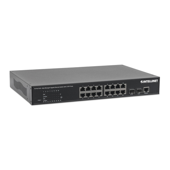
- Page 1 16-PORT P WEB-MANAGED GIGABIT ETHERNET SWITCH 2 SFP PORTS WITH MODEL 560931 INT-560931-UM-10-14-01...
-
Page 2: Fcc Warning
FCC Warning This equipment has been tested and found to comply with the limits for a Class A digital device, pursuant to Part 15 of the FCC rules. These limits are designed to provide reasonable protection against harmful interference in a residential installation. This equipment generates, uses, and can radiate radio frequency energy. -
Page 3: Table Of Contents
Content 1. P roduct O verview ....................... 8 1.1 M ajor M anagement F eatures ................... 8 1.2 P roduct S pecifications .................... 9 1.3 ... - Page 4 4.4.2.5 I P S ource G uard C onfiguration ................. 76 4.4.2.6 A RP I nspection .................... 78 4.4.3 S ecurity / A AA A uthentication S erver C onfiguration ........... 79 4.5 ...
- Page 5 4.16 V oice V LAN C onfiguration ................... 133 4.16.1 V oice V LAN / C onfiguration ................ 133 4.16.2 V oice V LAN / O UI C onfiguration .............. 135 4.17 ...
- Page 6 5.20 sFlow C onfiguration .................. 187 5.21 Diagnostic C ommands .................. 188 5.22 Maintenance C ommands ................. 189 6. ...
- Page 7 6.1.9.2 L LDP M ED N eighbors .................. 255 6.1.9.3 L LDP P oE ...................... 259 6.1.9.4 L LDP E EE ...................... 260 6.1.9.5 ...
-
Page 8: Product Overview
Product Overview This is a Layer 2 full-management Gigabit PoE switch, featuring 16 10/100/1000M RJ45 ports plus 2 Gigabit SFP open slots. The Ethernet ports support IEEE 802.3at PoE, and each port supports up to 30W. The SFP open slots are available for different types of SFP transceivers to extend the transmission distance up to 100 kilometers. -
Page 9: Product Specifications
1.2 Product Specifications Hardware Specification Total Ports 10/100/1000 Mbps Gigabit SFP Interface Autonegotiation and Auto-MDIX Backpressure for half duplex, Flow Control 802.3x for full duplex Console (RS-232) System (State / Color) LEDs Port (State: Link/Act / Color) PoE (State: On / Color) 416MHz Flash 16MB... - Page 10 IEEE 802.3 - 10Base-T IEEE 802.3u - 100Base-TX IEEE 802.3ab - 1000Base-T IEEE 802.3z - 1000Base-SX/LX IEEE 802.3x - Flow Control IEEE 802.1Q - VLAN IEEE 802.1p - Class of Service IEEE 802.1D - Spanning Tree Standards IEEE 802.1w - Rapid Spanning Tree IEEE 802.1s - Multiple Spanning Tree IEEE 802.3ad - Link Agregation Control Protocol (LACP) IEEE802.1v - Protocol VLAN...
- Page 11 IEEE 802.1s - Multiple Spanning Tree BPDU Guard, BPDU Filtering IGMP Snooping v1/v2/v3, MLD(IPv6) Snooping v1/v2 Multicast Maximum 8K Multicast Groups IGMP/MLD Querier, Router Port, Proxy, Immediate Leave Port Mirror (1 to 1, 1 to N, N to 1) Traffic Mirroring sFlow Dynamic MAC address management...
-
Page 12: Package Contents
CPU Monitor Per port POE State Enable/Disable Maximum system/port PoE power setting PoE Specifications Port power priority setting PD Status monitoring 1.3 Package Contents Before you start to install this switch, verify that the packaging contains the following items: One Network Switch One Power Cord One User Manual on CD... -
Page 13: Hardware Description
Front P anel The front panel of the switch consists of 16 (Model 560931) 10/100/1000 Base-TX RJ45 ports and 2 Gigabit uplink SFP ports. The LED Indicators are also located on the front panel. RJ-45... - Page 14 Hardware I nstallation The switch is usually mounted in a 19” rack, which is usually installed in an IT room or other secure place. The switch supports AC power input, PoE delivery and rackmount mounting. Make sure all the power cables, Ethernet cables, screws and the air circulation are well prepared and installed as directed below.
-
Page 15: Preparation For Management
3. Preparation for Management The switch provides both in-band and out-band configuration methods. Out-band Management: You can configure the switch using RS232 console cable if you don’t attach your admin PC to your network, or if you lose the network connection to your switch. -
Page 16: Preparation For Web Interface
Figure 3-2 PuTTY Configuration Figure 3-3 PuTTY Login Screen 3.2 Preparation for Web Interface The Web Management page allows you to use a standard Web browser — such as Microsoft Internet Explorer, Google Chrome or Mozilla Firefox — to configure the switch from anywhere on the network. - Page 17 4. Change your computer's IP address to 192.168.2.XX or another IP address that is located in the 192.168.2.x subnet (for example: IP Address: 192.168.2.30; Subnet Mask: 255.255.255.0). Launch the Web browser and log in. Launch the Web browser (Internet Explorer or Mozilla Firefox) on the PC. Type “http://192.168.2.1”...
-
Page 18: Preparation For Telnet/Ssh Interface
3.3 Preparation for Telnet/SSH Interface If your Window OS is Win XP, Win 2000 or an earlier version, you can access the Telnet console by default command. If your OS is Window 7 or a later version, download a terminal tool, such as HyperTeminal or PuTTY. - Page 19 3. After few seconds, the Telnet/SSH connection is established, the login page of Telnet/SSH is the same as console. The command line of Telnet, SSH and console are all the same. 19 ...
-
Page 20: Feature Configuration - Web Ui
4. Feature Configuration - Web UI The switch provides abundant software features. After you log in to the switch, you can start configuring the settings or monitoring the status. There is a question mark at the top right of the screen that you can click to get help from the system. -
Page 21: Ip Configuration
Buttons: Save: Click to save changes. Reset: Click to undo any changes made locally and revert to previously saved values. 4.1.2 IP Configuration: Configure the switch-managed IP information on this page. The Configured column is used to view or change the IP configuration. The Current column is used to show the active IP configuration. -
Page 22: Ipv6 Configuration
VLAN ID Provide the managed VLAND ID. The allowed range is 1 to 4095. Proxy When DNS proxy is enabled, the switch will relay DNS requests to the current configured DNS server on the switch, and reply as a DNS resolver to the client device on the network. Buttons Save: Click to save changes. -
Page 23: Ntp Configuration
Provide the IPv6 gateway address of this switch. The IPv6 address is in 128-bit records represented as eight fields of up to four hexadecimal digits with a colon separating each field (:). For example, “fe80::215:c5ff:fe03:4dc7.” The symbol :: is a special syntax that can be used as a shorthand way of representing multiple 16-bit groups of contiguous zeros;... -
Page 24: System Log Configuration
representing multiple 16-bit groups of contiguous zeros; but it can only appear once. It can also represent a legally valid IPv4 address. For example, “::192.1.2.34.” Buttons Save: Click to save changes. Reset: Click to undo any changes made locally and revert to previously saved values. 4.1.5 System Log Configuration: System Log is useful to allow the system administrator to monitor the switch’s events history. - Page 25 25 ...
-
Page 26: Power Reduction
4.2 Power Reduction 4.2.1 LED Power Reduction Configuration LED ntensity LED power consumption can be reduced by lowering the LED intensity. LED intensity could, for example, be lowered during nighttime, or they could be turned completely off. It is possible to configure LED intensity for each hour of the day. -
Page 27: Eee Configuration
4.2.2 EEE Configuration This page allows you to inspect and configure the current EEE port settings: EEE is a power-saving option that reduces the power usage when there is very low traffic utilization (or no traffic). EEE works by powering down circuits when there is no traffic. -
Page 28: Port Configuration
4.3 Port Configuration: This page displays current port configurations and link status. Some of the ports settings can also be configured here. Port This is the port number for this row. Link The current link state is displayed graphically. Green indicates the link is up and red that it is down. - Page 29 1000-X force SFP speed to 1000-X. 100-FX force SFP speed to 100-FX. Flow Control When Auto Speed is selected on a port, this section indicates the flow control capability that is advertised to the link partner. When a fixed-speed setting is selected, that is what is used. The Current Rx column indicates whether pause frames on the port are obeyed, and the Current Tx column indicates whether pause frames on the port are transmitted.
-
Page 30: Security Configuration
4.4 Security Configuration: The Security Configuration feature has three subsections: Switch, Network and AAA. 4.4.1 Security / Switch The switch settings include User Database, Privilege Levels, Authentication Method, SSH, HTTPs, Access Management, SNMP and RMON setting. 4.4.1.1 Security / Switch / Users Configuration This page provides an overview of the current users. -
Page 31: S Ecurity / S Witch / P Rivilege L Evels C Onfiguration
4.4.1.2 Security / Switch / Privilege Level Configuration: This page provides an overview of the privilege levels. 31 ... - Page 32 Group Name The name identifying the privilege group. In most cases, a privilege level group consists of a single module (e.g., LACP, RSTP or QoS), but a few of them contain more than one. The following description defines these privilege level groups in details: System: Contact, Name, Location, Time zone, Log.
-
Page 33: Security / Switch / Auth. Method
4.4.1.3 Security / Switch / Auth. Method This page allows you to configure how a user is authenticated when he logs in to the switch via one of the management client interfaces. The table has one row for each client type and a number of columns: Client The management client for which the configuration below applies. -
Page 34: Security / Switch / Ssh Configuration
4.4.1.4 Security / Switch / SSH Configuration With SSH, you can remotely connect to the switch by command line interface (CLI). The SSH connection can secure all the configuration commands you sent to the switch. It is also known as secured Telnet console. -
Page 35: Security / Switch / Access Management Configuration
Automatic Redirect Indicates the HTTPS redirect mode operation. Automatically redirects the Web browser to HTTPS when HTTPS mode is enabled. Possible modes: Enabled: Enable HTTPS redirect mode operation. Disabled: Disable HTTPS redirect mode operation. Buttons Save: Click to save changes. Reset: Click to undo any changes made locally and revert to previously saved values. - Page 36 HTTP / HTTPS Indicates that the host can access the switch from the HTTP / HTTPS interface if the host IP address matches the IP address range provided in the entry. SNMP Indicates that the host can access the switch from the SNMP interface if the host IP address matches the IP address range provided in the entry.
-
Page 37: Security / Switch / Snmp
4.4.1.7 Security / Switch / SNMP Simple Network Management Protocol (SNMP) is a protocol used for exchanging management information between network devices. The switch supports SNMP and equips lots of OIDs for remote management. All the OIDs are unique and correspond to one feature/command. The switch can support SNMP V1, V2c and V3. -
Page 38: Snmp Trap Configuration
SNMP Trap Configuration Configure SNMP trap on this page. Trap Mode Indicates the SNMP trap mode operation. Possible modes: Enabled: Enable SNMP trap mode operation. Disabled: Disable SNMP trap mode operation. Trap Version Indicates the SNMP trap-supported version. Possible versions: SNMPv1: Set SNMP trap-supported version 1. - Page 39 Trap Inform Mode Indicates the SNMP trap inform mode operation. Possible modes: Enabled: Enable SNMP trap inform mode operation. Disabled: Disable SNMP trap inform mode operation. Trap Inform Timeout (seconds) Indicates the SNMP trap inform timeout. The allowed range is 0 to 2147. Trap Inform Retry Times Indicates the SNMP trap inform retry times.
- Page 40 Community Indicates the community access string to permit access to the SNMPv3 agent. The allowed string length is 1 to 32, and the allowed content is ASCII characters from 33 to 126. The community string will be treated as a security name and map a SNMPv1 or SNMPv2c community string. Source Indicates the SNMP access source address.
- Page 41 Security Level Indicates the security model that this entry should belong to. Possible security models: NoAuth, NoPriv: No authentication and no privacy. Auth, NoPriv: Authentication and no privacy. Auth, Priv: Authentication and privacy. The value of security level cannot be modified if entry already exists. That means it must first be ensured that the value is set correctly.
- Page 42 SNMPv3 G roup C onfiguration Configure the SNMPv3 group table on this page: The entry index keys are Security Mode and Security Name. Delete Check to delete the entry. It will be deleted during the next save. Security Model Indicates the security model that this entry should belong to.
- Page 43 SNMPv3 V iew C onfiguration Configure the SNMPv3 view table on this page. The entry index keys are View Name OID Sub-tree. Delete Check to delete the entry. It will be deleted during the next save. View Name A string identifying the view name that this entry should belong to.
- Page 44 SNMPv3 A ccess C onfiguration Configure the SNMPv3 access table on this page. The entry index keys are Group Name, Security Model and Security Level. Delete Check to delete the entry. It will be deleted during the next save. Group Name A string identifying the group name that this entry should belong to.
-
Page 45: Rmon Statistics Configuration
4.4.1.8 RMON Statistics Configuration RMON is short for Remote Monitoring On Network. An RMON implementation typically operates in a client/server model. The monitoring device (probe) contains RMON software agents that collect information of the system and ports. The RMON software agent acts as a server, and the network management system (NMS) that communicate with it acts as a client. - Page 46 Indicates the index of the entry. The range is from 1 to 65535. Data Source Indicates the port ID to be monitored. If in a stacked switch, the value must add 1000* (switch ID-1); for example, if the port is switch 3 port 5, the value is 2005 Buttons Add new entry: Click to add a new community entry.
- Page 47 Buttons Add new entry: Click to add a new community entry. Save: Click to save changes. Reset: Click to undo any changes made locally and revert to previously saved values. RMON A larm C onfiguration Configure the RMON Alarm table on this page.
- Page 48 Sample Type The method of sampling the selected variable and calculating the value to be compared against the thresholds. Possible sample types: Absolute: Get the sample directly. Delta: Calculate the difference between samples (default). Value The value of the statistic during the last sampling period. Startup Alarm The method of sampling the selected variable and calculating the value to be compared against the thresholds.
- Page 49 RMON E vent C onfiguration Configure the RMON Event table on this page. The entry index key is ID. Delete Check to delete the entry. It will be deleted during the next save. Indicates the index of the entry. The range is from 1 to 65535. Desc Indicates this event, the string length is from 0 to 127;...
-
Page 50: Security /Network
4.4.2 Security /Network 4.4.2.1 Port Security Limit Control Configuration This page allows you to configure the Port Security Limit Control system and port settings. Limit Control allows for limiting the number of users on a given port. A user is identified by a MAC address and VLAN ID. - Page 51 System Configuration Mode Indicates if Limit Control is globally enabled or disabled on the switch. If globally disabled, other modules may still use the underlying functionality, but limit checks and corresponding actions are disabled. Aging Enabled If checked, secured MAC addresses are subject to aging as discussed under Aging Period. Aging Period If Aging Period is checked, then the aging period is controlled with this input.
- Page 52 Shutdown: If Limit + 1 MAC addresses is seen on the port, shut down the port. This implies that all secured MAC addresses will be removed from the port, and no new address will be learned. Even if the link is physically disconnected and reconnected on the port (by disconnecting the cable), the port will remain shut down.
-
Page 53: Security / Network / Network Access Server Configuration
4.4.2.2 Security / Network / Network Access Server Configuration This page allows you to configure the IEEE802.1X and MAC-based authentication system and port settings. The IEEE 802.1X standard defines a port-based access control procedure that prevents unauthorized access to a network by requiring users to first submit credentials for authentication. One or more central servers, the backend servers, determine whether the user is allowed access to the network. - Page 54 System C onfiguration Mode Indicates if NAS is globally enabled or disabled on the switch. If globally disabled, all ports are allowed forwarding of frames. Reauthentication Enabled If checked, successfully authenticated supplicants/clients are reauthenticated after the interval specified by the Reauthentication Period.
- Page 55 RADIUS-Assigned QoS Enabled RADIUS-assigned QoS provides a means to centrally control the traffic class to which traffic coming from a successfully authenticated supplicant is assigned on the switch. The RADIUS server must be configured to transmit special RADIUS attributes to take advantage of this feature (see RADIUS- Assigned QoS Enabled below for a detailed description).
- Page 56 Port C onfiguration The table has a number of columns that allow you to configure the port mode based on the IEEE 802.1X standard. Select the port and configure the settings. Port The port number for which the configuration below applies. Admin State If NAS is globally enabled, this selection controls the port's authentication mode.
- Page 57 Normal EAPOL frames are used in the communication between the supplicant and the switch. If more than one supplicant is connected to a port, the one that comes first when the port's link comes up will be the first one considered. If that supplicant doesn't provide valid credentials within a certain amount of time, another supplicant will get a chance.
- Page 58 this rule: • All 8 octets in the attribute's value must be identical and consist of ASCII characters in the range 0-3, which translates into the desired QoS Class in the range 0-3. RADIUS-Assigned VLAN Enabled When RADIUS-Assigned VLAN is both globally enabled and enabled (checked) for a given port, the switch reacts to VLAN ID information carried in the RADIUS Access-Accept packet transmitted by the RADIUS server when a supplicant is successfully authenticated.
- Page 59 allowed access on this VLAN. The switch will not transmit an EAPOL Success frame when entering the Guest VLAN. While in the Guest VLAN, the switch monitors the link for EAPOL frames, and if one such frame is received, the switch immediately takes the port out of the Guest VLAN and starts authenticating the supplicant according to the port mode.
-
Page 60: Security / Network / Access Control List Configuration
4.4.2.3 Security / Network / Access Control List Configuration Configure the ACL parameters (ACE) of each switch port. These parameters will affect frames received on a port unless the frame matches a specific ACE. The settings relate to the currently selected stack unit, as reflected by the page header. Port The logical port for the settings contained in the same row. - Page 61 Action Select whether forwarding is permitted ("Permit") or denied ("Deny"). The default value is "Permit." Rate Limiter ID Select which rate limiter to apply on this port. The allowed values are Disabled or the values through 16. The default value is "Disabled." Disabled Port Copy Select which port frames are copied on.
- Page 62 ACL Rate Limiters Configuration Configure the rate limiter for the ACL of the switch. Rate Limiter ID The rate limiter ID for the settings contained in the same row. Rate The allowed values are: 0-3276700 in pps. 0,100,200,300,…,1000000 in kbps.
-
Page 63: Access Control List Configuration
Access Control List Configuration This page shows the Access Control List (ACL), which is made up of the ACEs defined on this switch. Each row describes the ACE that is defined. The maximum number of ACEs is on each switch. Click on the lowest plus sign to add a new ACE to the list. - Page 64 Indicates the port copy operation of the ACE. Frames matching the ACE are copied to the port number. The allowed values are Disabled or a specific port number. When Disabled is displayed, the port copy operation is disabled. Mirror Specify the mirror operation of this port.
- Page 65 C onfiguration Configure an ACE (Access Control Entry) on this page. An ACE consists of several parameters. These parameters vary according to the frame type that you select. First select the ingress port for the ACE, and then select the frame type. Different parameter options are displayed depending on the frame type selected.
- Page 66 Ethernet Type: Only Ethernet Type frames can match this ACE. The IEEE 802.3 describes the value of Length/Type Field specifications to be greater than or equal to 1536 decimal (equal to 0600 hexadecimal). ARP: Only ARP frames can match this ACE. Notice the ARP frames won't match the ACE with ethernet type.
-
Page 67: Vlan Parameters
entering an SMAC value appears. SMAC Value When "Specific" is selected for the SMAC filter, you can enter a specific source MAC address. The legal format is "xx-xx-xx-xx-xx-xx". A frame that hits this ACE matches this SMAC value. DMAC Filter Specify the destination MAC filter for this ACE. - Page 68 ARP Parameters The ARP parameters can be configured when Frame Type "ARP" is selected. ARP/RARP Specify the available ARP/RARP opcode (OP) flag for this ACE. Any: No ARP/RARP OP flag is specified. (OP is "don't-care.") ARP: Frame must have ARP/RARP opcode set to ARP. RARP: Frame must have ARP/RARP opcode set to RARP.
- Page 69 0: ARP frames where SHA is not equal to the SMAC address. 1: ARP frames where SHA is equal to the SMAC address. Any: Any value is allowed ("don't-care"). RARP DMAC Match Specify whether frames can hit the action according to their target hardware address field (THA) settings. 0: RARP frames where THA is not equal to the DMAC address.
- Page 70 zero: IPv4 frames with a Time-to-Live field greater than zero must not be able to match this entry. non-zero: IPv4 frames with a Time-to-Live field greater than zero must be able to match this entry. Any: Any value is allowed ("don't-care"). IP Fragment Specify the fragment offset settings for this ACE.
- Page 71 ICMP Parameters ICMP Type Filter Specify the ICMP filter for this ACE. Any: No ICMP filter is specified (ICMP filter status is "don't-care"). Specific: If you want to filter a specific ICMP filter with this ACE, you can enter a specific ICMP value. A field for entering an ICMP value appears.
- Page 72 TCP/UDP Destination Number When "Specific" is selected for the TCP/UDP destination filter, you can enter a specific TCP/UDP destination value. The allowed range is 0 to 65535. A frame that hits this ACE matches this TCP/UDP destination value. TCP/UDP Destination Range When "Range"...
- Page 73 EtherType Filter Specify the Ethernet type filter for this ACE. Any: No EtherType filter is specified (EtherType filter status is "don't-care"). Specific: If you want to filter a specific EtherType filter with this ACE, you can enter a specific EtherType value.
-
Page 74: Switch / Network / Dhcp Configuration
4.4.2.4 Switch / Network / DHCP Configuration DHCP S nooping C onfiguration Configure DHCP Snooping on this page. Snooping Mode Indicates the DHCP snooping mode operation. Possible modes: Enabled: Enable DHCP snooping mode operation. When DHCP snooping mode operation is enabled, the DHCP request messages will be forwarded to trusted ports and only allow reply packets from trusted ports. - Page 75 DHCP R elay C onfiguration Configure DHCP Relay on this page. Relay Mode Indicates the DHCP relay mode operation. Possible modes: Enabled: Enable DHCP relay mode operation. When DHCP relay mode operation is enabled, the agent forwards and transfers DHCP messages between the clients and the server when they are not in the same subnet domain.
-
Page 76: Ip Source Guard Configuration
4.4.2.5 IP Source Guard Configuration S ource G uard C onfiguration This page provides IP Source Guard-related configuration. Mode of IP Source Guard Configuration Enable the Global IP Source Guard or disable the Global IP Source Guard. All configured ACEs will be lost when the mode is enabled. - Page 77 Static S ource G uard T able Delete Check to delete the entry. It will be deleted during the next save. Port The logical port for the settings. VLAN ID The VLAN ID for the settings. IP Address Allowed Source IP address.
-
Page 78: Arp Inspection
4.4.2.6 ARP Inspection I nspection This page provides ARP Inspection related configuration. Mode of ARP Inspection Configuration Enable the Global ARP Inspection or disable the Global ARP Inspection. Port Mode Configuration Specify ARP Inspection is enabled on which ports. Only when both Global Mode and Port Mode on a given port are enabled, ARP Inspection is enabled on this given port. - Page 79 Static A RP I nspection T able Delete Check to delete the entry. It will be deleted during the next save. Port The logical port for the settings. VLAND ID The VLAN ID for the settings.
-
Page 80: Security / Aaa Authentication Server Configuration
4.4.3 Security / AAA Authentication Server Configuration This page allows you to configure the Authentication Servers. Common S erver C onfiguration These setting are common for all of the Authentication Servers. Timeout The Timeout, which can be set to a number between 3 and 3600 seconds, is the maximum time to wait for a reply from a server. - Page 81 RADIUS Authentication Server Configuration The table has one row for each RADIUS Authentication Server and a number of columns: The RADIUS Authentication Server number for which the configuration below applies. Enabled Enable the RADIUS Authentication Server by checking this box. IP Address/Hostname The IP address or hostname of the RADIUS Authentication Server.
- Page 82 TACACS+ Authentication Server Configuration The table has one row for each TACACS+ Authentication Server and a number of columns: The TACACS+ Authentication Server number for which the configuration below applies. Enabled Enable the TACACS+ Authentication Server by checking this box. IP Address/Hostname The IP address or hostname of the TACACS+ Authentication Server.
-
Page 83: Aggregation Configuration
4.5 Aggregation Configuration Link Aggregation is also known as Port Trunking. It allows user using multiple ports in parallel to increase the link speed beyond the limits of a port and to increase the redundancy for higher availability. The switch support both Static and Dynamic link aggregation, LACP. The switch also supports different Hash mechanisms to forward traffic according to the MAC address or IP, Protocol Port Number. -
Page 84: Lacp - Dynamic Aggregation
TCP/UDP Port Number The TCP/UDP port number can be used to calculate the destination port for the frame. Check to enable the use of the TCP/UDP Port Number, or uncheck to disable. By default, TCP/UDP Port Number is enabled. Aggregation Group Configuration Group ID Indicates the group ID for the settings contained in the same row. - Page 85 Port The switch port number. LACP Enabled Controls whether LACP is enabled on this switch port. LACP will form an aggregation when two or more ports are connected to the same partner. LACP can form up to 12 LLAGs per switch and two GLAGs per stack.
-
Page 86: Loop Protection
4.6 Loop Protection page allows you to inspect the current Loop Protection configurations, and possibly change This them, as well. The loop protection feature is very important to protect the unexpected network loop, especially when you install the switch on the Internet. Incorrect installation, media failure or hacker attacks may create network loop. -
Page 87: Port Configuration
Port Configuration Port The switch port number of the port. Enable Controls whether loop protection is enabled on this switch port. Action Configures the action performed when a loop is detected on a port. The valid values: Shutdown Port: Shuts down the port until the Shutdown Time timeout. Shutdown Port and Log: Shuts down the port and log the status. -
Page 88: Spanning Tree
4.7 Spanning Tree The switch supports Multiple Spanning Tree Protocol (MSTP), Rapid Spanning Tree Protocol (RSTP) and Legacy Spanning Tree Protocol (STP). The STP and RSTP are combined and defined in IEEE 802.1D-2004, Rapid Spanning Tree Protocol. The RSTP protocol is applied to single network domain no matter how many VLANs are in your network. -
Page 89: Basic Settings
Basic Settings Protocol Version The STP protocol version setting. Valid values are STP, RSTP MSTP. Bridge Priority Controls the bridge priority. Lower numeric values have higher priority. The bridge priority plus the MSTI instance number, concatenated (linked) with the 6-byte MAC address of the switch, forms a Bridge Identifier. -
Page 90: Spanning Tree / Msti Mapping
Port Error Recovery Control whether a port in the error-disabled state automatically will be enabled after a certain time. If recovery is not enabled, ports have to be disabled and re-enabled for normal STP operation. The condition is also cleared by a system reboot. Port Error Recovery Timeout The time to pass before a port in the error-disabled state can be enabled. -
Page 91: Spanning Tree / Msti Priorities
Configuration Revision The revision of the MSTI configuration named above. This must be an integer between 0 and 65535. MSTI Mapping MSTI The bridge instance. The CIST is not available for explicit mapping, as it will receive the VLANs not explicitly mapped. -
Page 92: Spanning Tree / Cist Ports
MSTI The bridge instance. The CIST is the default instance, which is always active. Priority Controls the bridge priority. Lower numeric values have better priority. The bridge priority plus the MSTI instance number, concatenated with the 6-byte MAC address of the switch forms a Bridge Identifier. Buttons Save: Click to save changes. - Page 93 Port The switch port number of the logical STP port. STP Enabled Controls whether STP is enabled on this switch port. Path Cost Controls the path cost incurred by the port. Auto setting will set the path cost as appropriate by the physical link speed, using the 802.1D recommended values.
-
Page 94: Spanning Tree Msti Ports
Restricted TCN If enabled, causes the port not to propagate received topology change notifications and topology changes to other ports. If set it can cause temporary loss of connectivity after changes in a spanning tree's active topology as a result of persistently incorrect learned station location information. It is set by a network administrator to prevent bridges external to a core region of the network, causing address flushing in that region, possibly because those bridges are not under the full control of the administrator or the physical link state of the attached LANs transits frequently. - Page 95 This page contains MSTI port settings for physical and aggregated ports. Apart from the selected MSTI, the STP MSTI port settings also relate to the currently selected stack unit, as reflected by the page header. Port The switch port number of the corresponding STP CIST (and MSTI) port. Path Cost Controls the path cost incurred by the port.
-
Page 96: Mvr (Multicast Vlan Registration)
4.8 MVR (Multicast VLAN Registration) MVR is short for Multicast VLAN Registration. The MVR is a protocol for Layer 2 networks that enables multicast traffic from a source VLAN to be shared with client/subscriber VLANs. MVR is typically used for IPTV-like service. -
Page 97: Ipmc (Ip Multicast)
MVR Mode Enable/Disable the Global MVR. VLAN ID Specify the Multicast VLAN ID. Mode Enable MVR on the port. Type Specify the MVR port type on the port. Immediate Leave Enable the fast leave on the port. Buttons Save: Click to save changes. -
Page 98: Global Configuration
Global Configuration Snooping Enabled Enable Global IGMP Snooping. Unregistered IPMCv4 Flooding enabled Enable unregistered IPMCv4 traffic flooding. Unregistered IPMCv4 traffic is so-called unknown multicast. After selected, the unregistered multicast stream will be forwarded like normal packets. Once you un-selected it, such streams will be discarded. IGMP SSM Range SSM (Source-Specific Multicast) Range allows the SSM-aware hosts and routers to run the SSM service model for the groups in the address range. -
Page 99: Igmp Snooping Vlan Configuration
If an aggregation member port is selected as a router port, the whole aggregation will act as a router port. Fast Leave Enable the fast leave on the port. Multicast snooping Fast Leave processing allows the switch to remove an interface from the forwarding-table entry without first sending out group specific queries to the interface. - Page 100 IGMP Snooping VLAN Table Columns VLAN ID The VLAN ID of the entry. IGMP Snooping Enabled Enable the per-VLAN IGMP Snooping. Only up to 64 VLANs can be selected. IGMP Querier Enable the IGMP Querier in the VLAN. Compatibility Compatibility is maintained by hosts and routers taking appropriate actions depending on the versions of IGMP operating on hosts and routers within a network.
-
Page 101: Igmp Snooping / Port Group Filtering
Refresh : Refreshes the displayed table starting from the “VLAN” input fields. << : Updates the table starting from the first entry in the VLAN Table; i.e., the entry with the lowest VLAN >>: Update the table, staring with the entry after the last entry currently displayed. Save: To save the configuration. -
Page 102: Mld Snooping Configuration
Buttons Save: Click to save changes. Reset: Click to undo any changes made locally and revert to previously saved values. 4.9.2 MLD Snooping Configuration This section provides MLD Snooping-related configuration. The MLD is for IPv6 Multicast Snooping. The difference between the 2 IGMP and MLD is that the IGMP is applied to IPv4 Multicast stream while the MLD is applied to IPv6 Multicast stream. -
Page 103: Mld Snooping Vlan Configuration
If an aggregation member port is selected as a router port, the whole aggregation will act as a router port. Fast Leave Enable the fast leave on the port. Throttling Enable to limit the number of multicast groups to which a switch port can belong. Buttons Save: Click to save changes. - Page 104 Compatibility is maintained by hosts and routers taking appropriate actions depending on the versions of MLD operating on hosts and routers within a network. Allowed selections are MLD-Auto, Forced MLDv1 Forced MLDv2. The default compatibility value is MLD-Auto. Robustness Variable. The Robustness Variable allows tuning for the expected packet loss on a link. The allowed range is to 255.
-
Page 105: Ipmc / Mld Snooping / Port Group Filtering
4.9.2.3 IPMC / MLD Snooping / Port Group Filtering MLD Snooping Port Group Filtering Configuration Delete Check to delete the entry. It will be deleted during the next save. Port The logical port for the settings. Filtering Groups The IP Multicast Group that will be filtered. -
Page 106: Lldp Parameters
4.10 LLDP Parameters The Link Layer Discovery Protocol (LLDP) is a vendor-neutral link layer protocol. LLDP information is sent by devices from each of their interfaces at a fixed interval, in the form of an Ethernet Frame. Each frame contains one LLDP Data Unit (LLDPDU). Each LLDPDU is a sequence of Type-Length-Value (TLV) structures. - Page 107 transmitted to the neighboring units, signalling that the LLDP information isn't valid anymore. Tx Reinit controls the amount of seconds between the shutdown frame and a new LLDP initialization. Valid values are restricted to 1 - 10 seconds. LLDP Port Configuration The LLDP port settings relate to the currently selected stack unit, as reflected by the page header.
-
Page 108: Lldp Media Configuration
Port Descr Optional TLV: When checked, the "port description" is included in LLDP information transmitted. Sys Name Optional TLV: When checked, the "system name" is included in LLDP information transmitted. Sys Descr Optional TLV: When checked, the "system description" is included in LLDP information transmitted. Sys Capa Optional TLV: When checked, the "system capability"... - Page 109 Fast s tart r epeat c ount Fast start repeat count Rapid startup and Emergency Call Service Location Identification Discovery of endpoints is a critically important aspect of VoIP systems in general. In addition, it is best to advertise only those pieces of information which are specifically relevant to particular endpoint types (for example, only advertise the voice network policy to permitted voice-capable devices), both in order to conserve the limited LLDPU space and to reduce security and system integrity issues that can come with inappropriate knowledge...
- Page 110 Map Datum Map Datum is used for the coordinates given in these options: WGS84: (Geographical 3D) - World Geodesic System 1984, CRS Code 4327, Prime Meridian Name: Greenwich. NAD83/NAVD88: North American Datum 1983, CRS Code 4269, Prime Meridian Name: Greenwich; The associated vertical datum is the North American Vertical Datum of 1988 (NAVD88).
- Page 111 Street suffix Street suffix – Example : Ave, Platz. House no. House number – Example: 21. House no. suffix House number suffix – Example: A, ½. Landmark Landmark or vanity address – Example: Columbia University. Additional location info. Additional location info – Example: South Wing. Name Name (residence and office occupant) –...
- Page 112 Additional code – Example: 1320300003. Emergency C all S ervice Emergency Call Service (e.g., E911 and others), such as defined by TIA or NENA. Emergency Call Service Emergency Call Service ELIN identifier data format is defined to carry the ELIN identifier as used during emergency call setup to a traditional CAMA or ISDN trunk-based PSAP.
- Page 113 different sets of policies, based on the authenticated user identity or port configuration. It should be noted that LLDP-MED is not intended to run on links other than between Network Connectivity Devices and Endpoints, and therefore does not need to advertise the multitude of network policies that frequently run on an aggregated link interior to the LAN.
- Page 114 fields are ignored and only the DSCP value has relevance. Tagged indicates that the device is using the IEEE 802.1Q tagged frame format, and that both the VLAN ID and the Layer 2 priority values are being used, as well as the DSCP value. The tagged format includes an additional field, known as the tag header.
-
Page 115: Poe Configuration
4.11 PoE Configuration The function is applied to the PoE Switch model. If your switch is not a PoE switch, you will not see these configuration commands. This section allows you to inspect and configure the current port settings. Power Over Ethernet Configuration Reserved Power determined by There are three modes for configuring how the ports/PDs may reserve power. - Page 116 Power Management Mode There are 2 modes for configuring when to shut down the ports: 1. Actual Consumption: In this mode, the ports are shut down when the actual power consumption for all ports exceeds the amount of power that the power supply can deliver or if the actual power consumption for a given port exceeds the reserved power for that port.
- Page 117 Maximum Power The Maximum Power value contains a numerical value that indicates the maximum power in watts that can be delivered to a remote device. The maximum allowed value is 30 W. Buttons Save: Click to save changes. Reset: Click to undo any changes made locally and revert to previously saved values.
-
Page 118: Mac Address Table Configuration
4.12 MAC Address Table Configuration The MAC Address Table is configured on this page. Set timeouts for entries in the dynamic MAC Table and configure the static MAC table here. Aging C onfiguration By default, dynamic entries are removed from the MAC table after 300 seconds. This removal is also called aging. - Page 119 Static M AC T able C onfiguration The static entries in the MAC table are shown in this table. The static MAC table can contain 64 entries. The table is sorted first by VLAN ID and then by MAC address. Delete Check to delete the entry.
- Page 120 Adding a New Static Entry Click to add a new entry to the static MAC table. Specify the VLAN ID, MAC address and port members for the new entry. Click "Save." Buttons Save: Click to save changes. Reset: Click to undo any changes made locally and revert to previously saved values. ...
-
Page 121: Lan ( Virtual L An)
4.13 VLAN (Virtual LAN) VLAN is short for Virtual LAN (Local Area Network.) VLAN technology allows you to divide the physical ports into different logical groups. Each group is a virtual LAN, and the clients within the VLAN are a broadcast domain. While the clients in different VLANs need to communicate, the VLAN Overlapping setting or a additional upper router is needed. - Page 122 Indicates the name of the VLAN. Maximum length of the VLAN Name String is 32. VLAN Name can only contain letters or numbers. A VLAN name should contain at least one letter. A VLAN name can be edited for the existing VLAN entries or it can be added to the new entries. Port Members A row of check boxes for each port is displayed for each VLAN ID.
-
Page 123: Lan P Ort C Onfiguration
4.13.2 VLAN Port Configuration This page is used for configuring the switch’s port VLANs. Ether type for Custom S-ports This field specifies the ether type used for Custom S-ports. This is a global setting for all the Custom S-ports. - Page 124 Determines whether the port accepts all frames or only tagged/untagged frames. This parameter affects VLAN ingress processing. If the port only accepts tagged frames, untagged frames received on the port are discarded. By default, the field is set to All. Port VLAN Mode Configures the Port VLAN Mode.
-
Page 125: Private Vlans
4.14 Private VLANs The Private VLAN feature provides the ability to extend the capabilities of a "standard" VLAN. The additional concepts — Primary VLAN, Community VLAN and Isolated VLAN — are introduced in Private VLAN. The Primary VLAN can be considered the master in the master/slave relationship with the other two sub-types, Community VLAN and Isolated VLAN. -
Page 126: Port Isolation Configuration
A row of check boxes for each port is displayed for each private VLAN ID. To include a port in a Private VLAN, check the box. To remove or exclude the port from the Private VLAN, make sure the box is unchecked. - Page 127 Configuration Port Members A check box is provided for each port of a private VLAN. When checked, port isolation is enabled on that port. When unchecked, port isolation is disabled on that port. By default, port isolation is disabled on all ports. Buttons Save: Click to save changes.
-
Page 128: Cl / M Ac--Based V Lan C Onfiguration
4.15 VCL 4.15.1 VCL / MAC-Based VLAN Configuration The MAC-based VLAN entries can be configured here. This page allows for adding and deleting MAC-based VLAN entries and assigning the entries to different ports. This page shows only static entries. -
Page 129: Cl / P Rotocol--Based V Lan
4.15.2 VCL / Protocol-based VLAN Protocol to Group Mapping Table This page allows you to add new protocols to Group Name (unique for each Group) mapping entries and to see and delete already-mapped entries for the switch. Frame Type Frame Type can have one of the following values: Ethernet SNAP... - Page 130 In other words, if the value in the OUI field is 00-00-00, then the value of PID will be etype (0x0600-0xffff); and if the value of OUI is other than 00-00-00, then the valid value of PID will be any value from 0x0000 to 0xffff.
-
Page 131: Cl / I P S Ubnet--Based V Lan
VLAD I D Indicates the ID to which Group Name will be mapped. A valid VLAN ID ranges from 1-4095. Port Members A row of check boxes for each port is displayed for each Group Name to VLAN ID mapping. To include a port in a mapping, check the box. - Page 132 IP Address Indicates the IP address. Mask Length Indicates the network mask length. VLAN ID Indicates the VLAN ID. VLAN ID can be changed for the existing entries. Port Members A row of check boxes for each port is displayed for each IP subnet-based VLAN entry. To include a port in an IP subnet-based VLAN, check the box.
-
Page 133: Oice V Lan / C Onfiguration
4.16 Voice VLAN Configuration 4.16.1 Voice VLAN / Configuration The Voice VLAN feature enables voice traffic forwarding on the Voice VLAN so the switch can classify and schedule network traffic. It is recommended that there be two VLANs on a port: one for voice, one for data. - Page 134 Port Mode Indicates the Voice VLAN port mode. Possible modes: Disabled: from Voice VLAN. Auto: Enable auto detect mode. It detects whether there is VoIP phone attached to the specific port and configures the Voice VLAN members automatically. Forced: Force join to Voice VLAN. Port Security The Voice VLAN port security mode.
-
Page 135: Oice V Lan / O Ui C Onfiguration
4.16.2 Voice VLAN / OUI Configuration Configure the Voice VLAN OUI table on this page. The maximum entry number is 16. Modifying the OUI table will restart auto-detection of the OUI process. Delete to delete the entry. It will be deleted during the next save. Check Telephony OUI A telephony OUI address is a globally unique identifier assigned to a vendor by IEEE. -
Page 136: Qos
4.17 QoS 4.17.1 QoS / Ingress Port Classification This page allows you to configure the basic QoS Ingress Classification settings for all switch ports. The settings relate to the currently selected stack unit, as reflected by the page header. The displayed settings: Port The po... -
Page 137: Qos / Ingress Port Policer Config
Enabled: Use mapped versions of PCP and DEI for tagged frames. Click on the mode in order to configure the mode and/or mapping. DSCP Based Click to Enable DSCP Based QoS Ingress Port Classification. Buttons Save: Click to save changes. Reset: Click to undo any changes made locally and revert to previously saved values. -
Page 138: Qos / Port Scheduler
Rate Controls the rate for the policer. The default value is 500. This value is restricted to 100-1000000 when the "Unit" is "kbps" or "fps," and it is restricted to 1-3300 when the "Unit" is "Mbps" or "kfps." Unit Controls the unit of measure for the policer rate as kbps, Mbps, fps or kfps . -
Page 139: Qos / Egress Port Shapers
4.17.4 QoS / Egress Port Shapers This page provides an overview of QoS Egress Port Shapers for all switch ports. The ports belong to the currently selected stack unit, as reflected by the page header. The displayed settings: Port The logical port for the settings contained in the same row. -
Page 140: Qos / Port Tag Remarking
4.17.5 QoS / Port Tag Remarking This page provides an overview of QoS Egress Port Tag Remarking for all switch ports. The ports belong to the currently selected stack unit, as reflected by the page header. The displayed settings: Port The logical port for the settings contained in the same row. -
Page 141: Qos / Port Dscp Configuration
QoS / DSCP 4.17.6 QoS / Port DSCP Configuration This page allows you to configure the basic QoS Port DSCP Configuration settings for all switch ports. The settings relate to the currently selected stack unit, as reflected by the page header. The displayed settings: Port The Port column shows the list of ports for which you can configure DSCP ingress and egress settings. -
Page 142: Qos / Dscp-Based Qos Ingress Classification
Translation window for the specific DSCP. All: Classify all DSCP. Egress Port Egress Rewriting offers four options: Disabled: No Egress rewrite. Enable: Rewrite enabled without remapping. Remap DP Unaware: DSCP from analyzer is remapped and frame is remarked with remapped DSCP value. - Page 143 DSCP Maximum number of supported DSCP values is 64. Trust Controls whether a specific DSCP value is trusted. Only frames with trusted DSCP values are mapped to a specific QOs class and Drop Precedence Level. Frames with untrusted DSCP values are treated as non-IP frames.
-
Page 144: Qos / Dscp Translation
4.17.8 QoS / DSCP Translation This page allows you to configure the basic QoS DSCP Translation settings for all switches. DSCP translation can be done in Ingress or Egress. The displayed settings: DSCP Maximum number of supported DSCP values is 64, and valid DSCP values range from 0 to 63. Ingress Ingress side DSCP can be first translated to new a DSCP before using the DSCP for QoS class and DPL map. -
Page 145: Qos / Dscp Classification
Egress Configurable parameters for Egress side: 1. Remap DP0 Controls the remapping for frames with DP level 0. 2. Remap DP1 Controls the remapping for frames with DP level 1. 1. Remap DP0 Select the DSCP value from the menu to which you want to remap. DSCP value ranges form 0 to 63. 2. -
Page 146: Qos / Control List Configuration
Actual Drop Precedence Level. DSCP Select the classified DSCP value (0-63). Buttons Save: Click to save changes. Reset: Click to undo any changes made locally and revert to previously saved values. 4.17.10 QoS / Control List Configuration QoS Control List Configuration This page shows the QoS Control List(QCL), which is made up of the QCEs. - Page 147 LLC: Only (LLC) frames are allowed. SNAP: Only (SNAP) frames are allowed. IPv4: The QCE will match only IPV4 frames. IPv6: The QCE will match only IPV6 frames. SMAC Displays the OUI field of a Source MAC address; i.e., first three octet (byte) of a MAC address. DMAC Specify the type of Destination MAC addresses for incoming frames.
-
Page 148: Qos / Storm Control Configuration
Modification Buttons You can modify each QCE (QoS Control Entry) in the table using the following buttons: : Inserts a new QCE before the current row. : Edits the QCE. : Moves the QCE up the list. : Moves the QCE down the list. : Deletes the QCE. - Page 149 Rate The rate unit is packets per second (pps). Valid values: 1, 2, 4, 8, 16, 32, 64, 128, 256, 512, 1K, 2K, 4K, 8K, 16K, 32K, 64K, 128K, 256K, 512K, 1024K, 2048K, 4096K, 8192K, 16384K 32768K. Buttons Save: Click to save changes.
-
Page 150: Mirroring Configuration
4.18 Mirroring Configuration Configure port Mirroring on this page. To debug network problems, selected traffic can be copied, or mirrored, on a mirror port, where a frame analyzer can be attached to analyze the frame flow. The traffic to be copied on the mirror port is selected as follows: All frames received on a given port (also known as ingress or source mirroring). - Page 151 Disabled: Neither frames transmitted nor frames received are mirrored. Enabled Frames received and frames transmitted are mirrored on the mirror port. Note: For a given port, a frame is only transmitted once. It is therefore not possible to mirror Tx frames on the mirror port.
-
Page 152: Upnp Configuration
4.19 UPnP Configuration Configure UPnP on this page. Mode Indicates the UPnP operation mode. Possible modes are: Enabled: Enable UPnP mode operation. Disabled: Disable UPnP mode operation. When the mode is enabled, two ACEs are added automatically to trap UPNP related packets to CPU. The ACEs are automatically removed when the mode is disabled. -
Page 153: Flow C Onfiguration
4.20 sFlow Configuration Sampled Flow (sFlow) is a traffic monitoring technology mainly used to collect and analyze traffic statistics. The switch supports sFlow feature. The sFlow software agent collects traffic statistics and packet information from the sFlow-enabled interfaces on the switch, encapsulates them into sFlow packets. - Page 154 Sampler Type The configured sampler type on the port can be None, RX, TX or ALL. The default value is "none." Sampling Rate Configured sampling rate on the ports. Max Hdr Size Configured size of the header of the sampled frame. Counter Sampling Counter sampling performs periodic, time-based samplings or polling of counters associated with an interface enabled for sFlow.
-
Page 155: Feature Configuration - Cli
5. Feature Configuration - CLI The Command Line Interface (CLI) is the user interface to the switch’s embedded software system. You can view the system information, show the status, configure the switch and receive a response back from the system by keying in a command. After you log in to the switch through the console CLI, you can see the ">"... - Page 156 <name>: System name string. (1-255) Example: Contact Name = Orwell System>contact Orwell System Name Syntax: System Name [<name>] Parameters: <name>: System name string. (1-255) Example: Contact Name = poeswitch System>name poeswitch poeswitch:/> (After given system name, the prompt character will be changed automatically.) System Location Syntax:...
- Page 157 Syntax: IP NTP Server Add <server_index> <ip_addr_string> IP NTP Server Ipv6 Add <server_index> <server_ipv6> IP NTP Server Delete <server_index> Example: poeswitch:/IP>ntp ser add 1 192.168.100.1 poeswitch:/IP>ntp ser add 2 168.95.1.1 Check the NTP Server settings by below command: poeswitch:/IP>ntp conf IP NTP Configuration: ===================== NTP Mode : Enabled...
- Page 158 Router) Example: poeswitch:/IP>ipv6 setup 2001:DB8::250:8bff:fee8:f800 48 2001:DB8::250:8bff:fee8:f8ff IPv6 Ping Test Syntax: IP IPv6 Ping6 <ipv6_addr> [(Length <ping_length>)] [(Count <ping_count>)] [(Interval <ping_interval>)] Example: poeswitch:/IP>ipv6 ping6 2001:DB8::250:8bff:fee8:f800 NTP Mode Enable NTP Mode by below command: poeswitch:/IP>ntp mode en NTP Server Address Syntax: Setting Type the NTP Server address settings by below command:...
-
Page 159: Power Reduction
Information: poeswitch:/System>log level inf Warning: poeswitch:/System>log level war Error: poeswitch:/System>log level err Syntax: Clear Syslog System Log Clear [all|info|warning|error] poeswitch:/System>log clear all poeswitch:/System>log conf System Log Configuration System Log Configuration: ========================= System Log Server Mode : Enabled System Log Server Address : 192.168.2.100 System Log Level : Error ... -
Page 160: Port Configuration
Syntax: EEE Port EEE Mode [<port_list>] [enable|disable] Configuration Parameters: <port_list>: Port list or 'all', default: All ports enable : Enable EEE disable: Disable EEE Example: Enable Port 1-5 EEE>mode 1-5 en Syntax: Urgent Queue of Port EEE Urgent_queues [<port_list>] [<queue_list>] Parameters: <port_list>... -
Page 161: Security Configuration
Port MaxFrame [<port_list>] [<max_frame>] Size Example: Set port 1-24's maximum frame size to 9K jumbo frame Port>maxf 1-24 9600 Port Status Port>conf 1-2 Port Status Port Configuration: =================== Port State Mode Flow Control MaxFrame Power Excessive Link ---- -------- ----------- ------------ -------- -------- --------- ---- Enabled Auto Disabled... - Page 162 Security-Switch Configuration >securi swi Security -Switch Type “up” to move up one level or “/” to go to root level Group Security/Switch>? Command Groups: --------------- Security Switch Users : User management Security Switch Privilege: Privilege level Security Switch Auth : Authentication Security Switch SSH : Secure Shell...
- Page 163 Example: Set Privilege level of VLAN Group Security/Switch/Privilege>level group VLANs 10 10 10 10 (cro=10, crw=10, sro=10, srw=10) Security/Switch>pri level conf Privilege Level Configuration Table Privilege Level Configuration: ============================== Privilege Current Level: 15 Group Name Privilege Level CRO CRW SRO SRW -------------------------------- --- --- --- --- Aggregation 5 10...
- Page 164 ==================== HTTPS Mode: Enabled HTTPS Redirect Mod : Enabled Syntax: Access Management Security Switch Access Add <access_id> <start_ip_addr> <end_ip_addr> [web] [snmp ] [telnet] Example: Limit the IP range from the 192.168.2.1 to 192.168.2.10 can access the web UI. Security/Switch>access add 1 192.168.2.1 192.168.2.10 web Syntax: SNMP System Security Switch SNMP Mode [enable|disable]...
- Page 165 Security Switch SNMP Trap Community [<community>] Security Switch SNMP Trap Destination [<ip_addr_string>] Security Switch SNMP Trap IPv6 Destination [<ipv6_addr>] Example: Security/Switch/SNMP/Trap>mode ena Security/Switch/SNMP/Trap>version 2c Security/Switch/SNMP/Trap>community public Security/Switch/SNMP/Trap>destination 192.168.2.100 Result: Trap Mode : Enabled Trap Version : 2c Trap Community : public Trap Destination : 192.168.2.100...
- Page 166 In Security/Switch Group, the system supports 4 types of RMON RMON groups. Follow the RMON Syntax to add the entries. Syntax: Security/Switch>rmon ? Statistics: Security Switch RMON Statistics Add <stats_id> <data_source> Security Switch RMON Statistics Delete <stats_id> Security Switch RMON Statistics Lookup [<stats_id>] Histroy: Security Switch RMON History Add <history_id>...
- Page 167 Security Network Limit Reopen [<port_list>] Example: Security/Network>limit port 1 enabl Security/Network>limit limit 1 5 Security/Network>limit action 1 trap Network Access Server Configuration (also known as IEEE 802.1X) Syntax: NAS System Mode: Configuration Security Network NAS Mode [enable|disable] Security Network NAS Reauthentication [enable|disable] Time Settings Security Network NAS ReauthPeriod [<reauth_period>] Security Network NAS EapolTimeout [<eapol_timeout>]...
- Page 168 Parameters: <port_list> : Port list or “all”; default: All ports permit : Permit forwarding (default) deny : Deny forwarding <rate_limiter> : Rate limiter number (1-15) or “disable” <port_redirect>: Port list for copy of frames or “disable” <mirror> : Mirror of frames: enable|disable <logging>...
- Page 169 [<tcp_flags>])] [permit|deny] [<rate_limiter>] [<port_redirect>] [<mirror>] [<logging>][<shutdown>] Parameters: <ace_id> : ACE ID (1-256), default: Next available ID <ace_id_next> : Next ACE ID (1-256), default: Add ACE last port : Port ACE keyword <port_list> : Port list or “all”; default: All ports policy : Policy ACE keyword <policy>...
- Page 170 Edit one ACE: Security/Network/ACL>add 1 port 1-5 policy 2 8 any ACE ID 1 modified last Result: Type Port Policy Frame Action Rate L. Port C. Mirror Counter ------- -------- -------- ----- ------ -------- -------- -------- ------- User 2 /0x8 Any Permit Disabled Disabled Disabled User 6-10...
- Page 171 Security/Network>ip source guard limit 1-10 2 (limit 2 MAC Address) Syntax: IP Source Guard Security Network IP Source Guard Entry [<port_list>] Static Table add|delete <vid> <allowed_ip> <allowed_mac> Example: Security/Network>ip source guard entry 5 add 2 192.168.2.101 001122334455 Result: IP Source Guard Entry Table: Type Port VLAN IP Address MAC Address...
-
Page 172: Aggregation Configuration
Syntax: RADIUS Accounting Security AAA ACCT_RADIUS [<server_index>] Server [enable|disable] [<ip_addr_string>] [<secret>] [<server_port>] Example: Security>aaa ACCT_radi 1 en 192.168.2.200 password 1813 Syntax: TACACS+ Security AAA TACACS+ [<server_index>] [enable|disable] Authentication Server [<ip_addr_string>] [<secret>] [<server_port>] Example: Security>aaa tacacs+ 1 en 192.168.2.200 password 49 Security>aaa con AAA Configuration AAA Configuration:... -
Page 173: Loop Protection
Static Aggregation Configuration Syntax: Aggregation Group Aggr Add <port_list> [<aggr_id>] Configuration Example: Add port 5-8 to Group 1 >aggr add 5-8 1 >aggr del 1 (Delete the group 1) Syntax: Hash Code Aggr Mode [smac|dmac|ip|port] [enable|disable] Contributors smac = Source MAC Address dmac = Destination MAC Address ip = IP Address port = TCP/UDP Port Number... -
Page 174: Spanning Tree
Shutdown Time >loop protect shut 200 (200 seconds) Port Configuration Syntax: Loop Protection - Port Loop Protect Port Mode [<port_list>] [enable|disable] Configuration Loop Protect Port Action [<port_list>] [shutdown|shut_log|log] Loop Protect Port Transmit [<port_list>] [enable|disable] Example: Loop/Protect>port mode 1 en Loop/Protect>port action 1 shut_log (Shutdown Port and Log) Loop/Protect>port transmit 1 en... - Page 175 Valid values are in the range 1 to 10 BPDUs per second.) Syntax: Advanced Setting STP bpduFilter [enable|disable] STP bpduGuard [enable|disable] STP recovery [<timeout>] recovery timeout time is set, the recovery is enabled After automatically.) MSTI Mapping Syntax: MSTI/VLAN Mapping STP Msti Add <msti>...
-
Page 176: Mvr
STP>msti port cost 0 all 100000 (Path cost = 100000) Syntax: Port Priority STP Msti Port Priority [<msti>] [<port_list>] [<priority>] Parameters: <msti> : STP bridge instance no (0-7, CIST=0, MSTI1=1, ...) <port_list>: Port list or 'all'. Port zero means aggregations. <priority>... -
Page 177: Ipmc
Inactive Port: 1,3-5,8-26 [Channel Setting of Source2(VID-2)] <Empty Channel Table> MVR Immediate Leave Setting Port Immediate Leave ---- --------------- Enabled Enabled Enabled Enabled Enabled Enabled Enabled Enabled Enabled Enabled Disabled Disabled 5.9 IPMC Feature Command Line IGMP Snooping Configuration IGMP Snooping Syntax: Enable... -
Page 178: Lldp Configuration
IPMC Router [mld|igmp] [<port_list>] [enable|disable] Configuration IPMC Fastleave [mld|igmp] [<port_list>] [enable|disable] (Router Port, Fast IPMC Throttling [mld|igmp] [<port_list>] [limit_group_number] Leave, Throttling) Example: IPMC>router igmp 25-26 en (Port 25-26 are router ports) IPMC>Fast igmp 1-24 en (Enable IGMP Fast Leave on P1-24) IPMC>thro igmp 1-2 5 (Throtting of Port 1, 2 is 5 groups.) VLAN Configuration... -
Page 179: Power Over Ethernet Configuration
LLDP>mode 1-10 en (Port 1-10 are enabled) LLDP>mode 1-26 en (Port 1-26 are enabled) CDP aware Syntax: LLDP cdp_aware [<port_list>] [enable|disable] Example: Enable CDP on Port 1-5 LLDP>cdp_a 1-5 en (CDP on Port 1-5 are enabled) LLDP Optional_TLV Syntax: LLDP optional_TLV [<port_list>] Parameters [port_descr|sys_name|sys_descr|sys_capa|mgmt_addr]... -
Page 180: Mac Address Table Configuration
PoE>mode 1-24 poe+ PoE Status Primary Power Supply PoE>prim Primary Power Supply --------------------- 200 [W] Port Status PoE>sta Port PD Class Port Status Power Used [W] Current Used [mA] ---- -------- --------------------------------------- -------------- ------- ---------- No PD detected No PD detected ... -
Page 181: Vlan Configuration
--- ----------------- ----- 00-10-15-02-25-2a 1-5 0b-16-21-2c-37-42 1-10 5.13 VLAN Configuration Feature Command Line VLAN Configuration VLAN Membership Syntax: VLAN Add <vid>|<name> [<ports_list>] VLAN Name Add <name> <vid> Example: VLAN>add 3 5-8 (Add port 5-8 to VLAN 3) VLAN>name add vlan3 3 (vlan3 is the name of VLAN 3) Port Configuration Syntax:... -
Page 182: Vcl Configuration
5.15 VCL Configuration Feature Command Line MAC-based VLAN Configuration MAC-based VLAN Syntax: VCL Macvlan Add <mac_addr> <vid> [<port_list>] Configuration Example: VCL/Macvlan>add 001122334455 10 1-4 Result: VCL/Macvlan>conf MAC Address Ports ----------------- ---- ----- 00-0b-16-21-2c-37 10 Protocol-based VLAN Configuration Protocol to Group Syntax: VCL ProtoVlan Protocol Add Eth2 <ether_type>|arp|ip|ipx|at <group_id>... -
Page 183: Voice Vlan Configuration
VCL/IPVlan>add 1 192.168.10.0/24 10 1-10 Result: VCE ID IP Address Mask Length VID Ports ------ --------------- ----------- ---- ----- 192.168.10.0 1-10 5.16 Voice VLAN Configuration Feature Command Line Voice VLAN Configuration Voice VLAN Syntax: Voice VLAN Mode [enable|disable] Configuration Voice VLAN ID [<vid>] Voice VLAN Agetime [<age_time>]... -
Page 184: Qos Configuration
Voice/VLAN>oui lookup Voice VLAN OUI Table: ===================== Telephony OUI Description ------------- ----------- 00-01-E3 Siemens AG phones 00-03-6B Cisco phones 00-0F-E2 H3C phones 00-60-B9 Philips and NEC AG phones 00-D0-1E Pingtel phones 00-E0-75 Polycom phones 00-E0-BB 3Com phones 00-12-77 00-12-08 hello ... - Page 185 QoS/Port/Policer>mode 1-2 en QoS/Port/Policer>rate 1-2 300 QoS/Port/Policer>unit 1-2 kbps QoS/Port/Policer>flow 1-2 en Port Scheduler Syntax: Syntax: QoS Port Scheduler Mode [<port_list>] [strict|weighted] Example: QoS/Port/Scheduler>mode 1-2 stric (Strict Priority) QoS/Port/Scheduler>mode 1-2 wei (Weighted) QoS Egress Port Scheduler and Shapers QoS/Port/Scheduler>wei 1-2 1 30 (Port 1-2, Q1=30) QoS/Port/Scheduler>wei 1-2 2 30 (Port 1-2, Q2=30) Port Shaping Syntax:...
-
Page 186: Mirroring Configuration
DSCP Syntax: QoS Port DSCP Translation [<port_list>] [enable|disable] Configuration QoS Port DSCP Classification [<port_list>] [none|zero|selected|all] QoS Port DSCP EgressRemark [<port_list>] [disable|enable|remap_dp_unaware|remap_dp_aware] Note: DSCP is an advanced QoS setting. Follow the DSCP table of upper access/core switch to configure the table. The table of the whole network must be unified. -
Page 187: Upnp Configuration
5.19 UPnP Configuration Feature Command Line UPnP Configuration UPnp Configuration Syntax: UPnP Configuration UPnP Mode [enable|disable] UPnP TTL [<ttl>] UPnP AdvertisingDuration [<duration>] Example: UPnP>mode en UPnP>ttl 5 (Default=4) UPnP>adver 200 (Default=100) Result: UPnP Configuration: =================== UPnP Mode : Enabled UPnP TTL UPnP Advertising Duration : 200 ... -
Page 188: Diagnostic Commands
sFlow>flow 1-2 10 128 (Enable FlowSample on port 1-2, rate=10, max. size=128) sFlow>coun 1-2 5 (Enable CounterPoller of port 1-2, and set interval to 5) sFlow>statistic sample 1-2 Per-Port Statistics: ==================== Port Rx Flow Samples Tx Flow Samples Counter Samples ---- --------------- --------------- --------------- ... -
Page 189: Maintenance Commands
Port>veriphy 24 Starting VeriPHY, please wait Port Pair A Length Pair B Length Pair C Length Pair D Length ----- ------- ------- ------- ------- ------- ------- ------- ------ 5.22 Maintenance Commands Feature Command Line Maintenance Commands Restart Device Syntax: System Reboot Example:... - Page 190 Note 2: While the firmware uploading process is started, don't shut down the switch! 190 ...
-
Page 191: Web Configuration - Monitor, Diagnostic, Maintenance
6. Web Configuration - Monitor, Diagnostic, Maintenance 6.1 Monitor 6.1.1 Monitor / System 6.1.1.1 Monitor / System / Information The switch system information is provided here. Contact The system contact configured in Configuration | System | Information | System Contact. Name The system name configured in Configuration | System | Information | System Name. -
Page 192: Cpu Load
System Uptime The period of time the device has been operational. Software Version The software version of this switch. Software Date The date when the switch software was produced. Buttons Auto-refresh : Check this box to enable an automatic refresh of the page at regular intervals. Refresh : Click to refresh the page;... - Page 193 The ID (>= 1) of the system log entry. Level The level of the system log entry. The following level types are supported: Info: Information level of the system log. Warning: Warning level of the system log. Error: Error level of the system log. All: All levels.
-
Page 194: System / Detailed Log
6.1.1.4 System / Detailed Log The switch detailed log information is provided here. The ID (>= 1) of the system log entry. Message The detailed message of the system log entry. Buttons Refresh : Updates the system log entry to the current entry ID. /<<: Updates the system log entry to the first available entry ID. -
Page 195: Monitor / Port State
6.1.2 Monitor / Port State 6.1.2.1 Port State This page provides an overview of the current switch port states. The port states are illustrated as follows: RJ45 ports SFP ports State Disabled Down Link Buttons Auto-refresh : Check this box to refresh the page automatically. Automatic refresh occurs at regular intervals. -
Page 196: Traffic Overview
6.1.2.2 Traffic Overview This page provides an overview of general traffic statistics for all switch ports. The displayed counters: Port The logical port for the settings contained in the same row. Packets The number of received and transmitted packets per port. Bytes The number of received and transmitted bytes per port. -
Page 197: Qos Statistics
6.1.2.3 QoS Statistics This page provides statistics for the different queues for all switch ports. The displayed counters: Port The logical port for the settings contained in the same row. There are eight QoS queues per port. Q0 is the lowest priority queue. Rx/Tx The number of received and transmitted packets per queue. -
Page 198: Qcl Status
6.1.2.4 QCL Status This page shows the QCL status of different QCL users. Each row describes the QCE that is defined. It is a conflict if a specific QCE is not applied to the hardware due to hardware limitations. The maximum number of QCEs is on each switch. - Page 199 DPL: Drop Precedence Level; if a frame matches the QCE, then the DP level will set to the value displayed in the DPL column. DSCP: If a frame matches the QCE, then DSCP will be classified with the value displayed in the DSCP column.
-
Page 200: Detailed Port Statistics
6.1.2.5 Detailed Port Statistics This page provides detailed traffic statistics for a specific switch port. Use the port select box to select which switch port details to display. The displayed counters are the totals for receive and transmit, the size counters for receive and transmit, and the error counters for receive and transmit. - Page 201 The number of received and transmitted (good and bad) multicast packets. Rx and Tx Broadcast The number of received and transmitted (good and bad) broadcast packets. Rx and Tx Pause A count of the MAC Control frames received or transmitted on this port that have an opcode indicating a PAUSE operation.
- Page 202 Long frames are frames that are longer than the configured maximum frame length for this port. Transmit E rror C ounters Tx Drops The number of frames dropped due to output buffer congestion. Tx Late/Exc. Coll. The number of frames dropped due to excessive or late collisions.
-
Page 203: Monitor / Security
6.1. 3 Monitor / Security 6.1.3.1 Security / Access Management Statistics This page provides statistics for access management. Interface The interface type through which the remote host can access the switch. Received Packets Number of received packets from the interface when access management mode is enabled. Allowed Packets Number of allowed packets from the interface when access management mode is enabled. -
Page 204: Security / Network
6.1.3.2 Security / Network Port Security Switch Status This page shows the Port Security status. Port Security is a module with no direct configuration. Configuration comes indirectly from other modules — the user modules. When a user module has enabled port security on a port, the port is set up for software-based learning. - Page 205 Port Status The table has one row for each port on the switch and a number of columns: Port The port number for which the status applies. Click the port number to see the status for this particular port. Users Each of the user modules has a column that shows whether that module has enabled Port Security or not.
- Page 206 Port Security Port Status This page shows the MAC addresses secured by the Port Security module. Port Security is a module with no direct configuration. Configuration comes indirectly from other modules: the user modules. When a user module has enabled port security on a port, the port is set up for software-based learning. In this mode, frames from unknown MAC addresses are passed on to the port security module, which in turn asks all user modules whether to allow this new MAC address to forward or block it.
- Page 207 If aging is disabled or a user module has decided to hold the MAC address indefinitely, a dash (-) will be shown. Buttons Refresh: Click to refresh the page immediately. Auto-refresh: Click this box to enable an automatic refresh of the page at regular intervals. ...
- Page 208 The user name (supplicant identity) carried in the most recently received Response Identity EAPOL frame for EAPOL-based authentication, and the source MAC address from the most recently received frame from a new client for MAC-based authentication. QoS Class QoS Class assigned to the port by the RADIUS server if enabled. Port VLAN ID The VLAN ID that NAS has put the port in.
- Page 209 Port Counters EAPOL Counters These supplicant frame counters are available for the following administrative states: • Force Authorized • Force Unauthorized • Port-based 802.1X • Single 802.1X • Multi 802.1X EAPOL Counters Direction Name IEEE Name Description The number of valid EAPOL frames Total dot1xAuthEapolFramesRx of any type that have been received...
- Page 210 by the switch. The number of EAPOL Request Request ID dot1xAuthEapolReqIdFramesTx Identity frames that have been transmitted by the switch. The number of valid EAPOL Request frames (other than Request Requests dot1xAuthEapolReqFramesTx Identity frames) that have been transmitted by the switch. Backend Server Counters These backend (RADIUS) frame counters are available for the following administrative states: •...
- Page 211 client (right-most table). 802.1X-based: Counts the number of times that the switch sends an EAP Request packet Other following the first to dot1xAuthBackendOtherRequestsToSupplicant Requests the supplicant. Indicates that the backend server chose an EAP-method. MAC-based: Not applicable. 802.1X- and MAC-based: Counts the number of times that the switch...
- Page 212 supplicant's first response packet to the backend server. Indicates the switch attempted communication with the backend server. Possible retransmissions are not counted. MAC-based: Counts all the backend server packets sent from the switch towards the backend server for a given port (left-most table) or client (right-most table).
- Page 213 802.1X-based: The protocol version number carried in the most Version dot1xAuthLastEapolFrameVersion recently received EAPOL frame. MAC-based: Not applicable. 802.1X-based: The user name (supplicant identity) carried in the most recently received Response Identity EAPOL Identity frame. MAC-based: Not applicable. Selected Counters Selected Counters The Selected Counters table is visible when the port is in one of the following administrative states: •...
- Page 214 Security module. State The client can either be authenticated or unauthenticated. In the authenticated state, it is allowed to forward frames on the port, and in the unauthenticated state, it is blocked. As long as the backend server hasn't successfully authenticated the client, it is unauthenticated. If an authentication fails for one or the other reason, the client will remain in the unauthenticated state for Hold Time seconds.
- Page 215 • MAC-based Auth.X Click to clear both the port counters and all of the attached client's counters. The "Last Client" will not be cleared, however. This button is available in the following modes: • Multi 802.1X • MAC-based Auth.X Click to clear only the currently selected client's counters.
- Page 216 Indicates the frame type of the ACE. Possible values: Any: The ACE will match any frame type. EType: The ACE will match Ethernet Type frames. Note that an Ethernet Type based ACE will not get matched by IP and ARP frames. ARP: The ACE will match ARP/RARP frames.
-
Page 217: Dhcp Snooping Statistics
Conflict Indicates the hardware status of the specific ACE. The specific ACE is not applied to the hardware due to hardware limitations. Buttons : Select the ACL status from this drop-down list. Refresh: Click to refresh the page immediately. Auto-refresh: Click this box to enable an automatic refresh of the page at regular intervals. - Page 218 Rx and Tx Decline The number of decline (option 53 with value 4) packets received and transmitted. Rx and Tx ACK The number of ACK (option 53 with value 5) packets received and transmitted. Rx and Tx NAK The number of NAK (option 53 with value 6) packets received and transmitted. Rx and Tx Release The number of release (option 53 with value 7) packets received and transmitted.
-
Page 219: Dhcp Relay Statistics
DHCP Relay Statistics This page provides statistics for DHCP relay. Server Statistics Transmit to Server The number of packets that are relayed from client to server. Transmit Error The number of packets that resulted in errors while being sent to clients. Receive from Server The number of packets received from server. - Page 220 Receive Bad Remote ID The number of packets whose Remote ID option did not match a known Remote ID. Client Statistics Transmit to Client The number of relayed packets from server to client. Transmit Error The number of packets that resulted in an error while being sent to servers. Receive from Client The number of received packets from server.
- Page 221 20 entries from the beginning of the Dynamic ARP Inspection Table. The "Start from port address," "VLAN," "MAC address" and "IP address" input fields allow the user to select the starting point in the Dynamic ARP Inspection Table. Clicking the button will update the displayed table starting from that or the closest next Dynamic ARP Inspection Table match.
- Page 222 Network / Dynamic I P S ource G uard T able Entries in the Dynamic IP Source Guard Table are shown on this page. The Dynamic IP Source Guard Table is sorted first by port, then by VLAN ID, then by IP address, and then by MAC address. Navigating the IP Source Guard Table Each page shows up to 99 entries from the Dynamic IP Source Guard table, default being 20, selected through the "entries per page"...
-
Page 223: Security / Aaa
Source MAC address. Buttons Auto-refresh: Click this box to enable an automatic refresh of the page at regular intervals. Refresh: Click to refresh the page immediately. Clear: Flushes all dynamic entries. /<<: Updates the table starting from the first entry in the Dynamic IP Source Guard Tables. >>: Updates the table, starting with the entry after the last entry currently displayed. - Page 224 to accept access attempts. Dead (X seconds left): Access attempts were made to this server, but it did not reply within the configured timeout. The server has temporarily been disabled, but will get re-enabled when the dead-time expires. The number of seconds left before this occurs is displayed in parentheses. This state is only reachable when more than one server is enabled.
- Page 225 RADIUS A uthentication S tatistics This page provides detailed statistics for a particular RADIUS server. RADIUS Authentication Statistics The statistics map closely to those specified in RFC4668-RADIUS.Authentication Client MIB. Use the server select box to switch between the backend servers to show details. Packet Counters RADIUS authentication server packet counter.
- Page 226 authenticators or Message Authenticator attributes or unknown types are not included as malformed access responses. The number of RADIUS Access-Response radiusAuthClientExtBad packets containing invalid authenticators or Authenticators Authenticators Message Authenticator attributes received from the server. The number of RADIUS packets that were radiusAuthClientExtUnk Unknown Types received with unknown types from the server...
- Page 227 Name RFC4668 Name Description Shows the state of the server. It takes one of the following values: Disabled: The selected server is disabled. Not Ready: The server is enabled, but IP communication is not yet up and running. Ready: The server is enabled, IP communication is up and running, and the RADIUS module is ready to accept access attempts.
- Page 228 server. The number of RADIUS packets of radiusAccClientExtUnknow Unknown Types unknown types that were received from the nTypes server on the accounting port. The number of RADIUS packets that were Packets radiusAccClientExtPackets received from the server on the accounting Dropped Dropped port and dropped for some other reason.
- Page 229 attempts. Dead (X seconds left): Accounting attempts were made to this server, but it did not reply within the configured timeout. The server has temporarily been disabled, but will get re-enabled when the dead-time expires. The number of seconds left before this occurs is displayed in parentheses.
-
Page 230: Switch / Snmp / Rmon
6.1.3.4 Switch / SNMP / RMON RMON Statistics Overview This page provides an overview of RMON statistics entries. The displayed counters: Data Source The port ID which wants to be monitored. Drop The total number of events in which packets were dropped by the probe due to lack of resources. Octets The total number of octets of data (including those in bad packets) received on the network. - Page 231 octets) of between 64 and 1518 octets. Under-size The total number of packets received that were less than 64 octets. Over-size The total number of packets received that were longer than 1518 octets. Frag. The number of frames whose size is less than 64 octets received with invalid CRC. Jabb.
- Page 232 RMON History Overview This page provides an overview of RMON history entries. The displayed fields: History Index Indicates the index of History control entry. Sample Index Indicates the index of the data entry associated with the control entry. Sample Start The total number of events in which packets were dropped by the probe due to lack of resources.
- Page 233 The total number of good packets received that were directed to a multicast address. CRCErrors The total number of packets received that had a length (excluding framing bits, but including FCS octets) of between 64 and 1518 octets. Undersize The total number of packets received that were less than 64 octets.
- Page 234 Indicates the index of Alarm control entry. Interval Indicates the interval in seconds for sampling and comparing the rising and falling threshold. Variable Indicates the particular variable to be sampled. Sample Type The method of sampling the selected variable and calculating the value to be compared against the thresholds.
- Page 235 RMON Event Overview This page provides an overview of RMON event entries. The displayed fields: Event Index Indicates the index of the event entry. Log Index Indicates the index of the log entry. Log TIme Indicates Event log time. Log Description Indicates the Event description.
-
Page 236: Lacp System Status
6.1.4 LACP System Status 6.1.4.1 System Status This page provides a status overview for all LACP instances. Aggr ID The Aggregation ID associated with this aggregation instance. For LLAG, the ID is shown as “isid:aggr-id”; and for GLAGs as “aggr-id.” Partner System ID The system ID (MAC address) of the aggregation partner. -
Page 237: Lacp Port Status
6.1.4.2 LACP Port Status This page provides a status overview for LACP status for all ports. Port The switch port number. LACP “Yes” means that LACP is enabled and the port link is up. “No” means that LACP is not enabled or that the port link is down. -
Page 238: Lacp Statistics
6.1.4.3 LACP statistics This page provides an overview for LACP statistics for all ports. Port The switch port number. LACP Received Shows how many LACP frames have been received at each port. LACP Transmitted Shows how many LACP frames have been sent from each port. Discarded Shows how many unknown or illegal LACP frames have been discarded at each port. -
Page 239: Loop Protection
6.1.5 Loop Protection This page displays the loop protection port status of the switch. Port The switch port number of the logical port. Action The currently configured port action. Transmit The currently configured port transmit mode. Loops The number of loops detected on this port. Status The current loop protection status of the port. -
Page 240: Stp Bridge Status
6.1.6 STP Bridge Status This page provides a status overview of all STP bridge instances. 6.1.6.1 Bridge Status The displayed table contains a row for each STP bridge instance, where the column displays the following information: MSTI The Bridge Instance. This is also a link to the STP Detailed Bridge Status Bridge ID The Bridge ID of this Bridge instance. -
Page 241: Stp Port Status
The time since last Topology Change occurred. Buttons Refresh: Click to refresh the page immediately. Auto-refresh : Check this box to enable an automatic refresh of the page at regular intervals. 6.1.6.2 STP Port Status This page displays the STP CIST port status for physical ports of the switch. STP port status: Port The switch port number of the logical STP port. -
Page 242: Stp Port Statistics
6.1.6.3 STP Port Statistics This page displays the STP port statistics counters of bridge ports in the switch. The STP port statistics counters: Port The switch port number of the logical STP port. MSTP The number of MSTP Configuration BPDUs received/transmitted on the port. RSTP The number of RSTP Configuration BPDUs received/transmitted on the port. -
Page 243: Mvr Status
6.1.7 MVR Status 6.1.7.1 Statistics This page provides MVR Statistics information. VLAN ID The Multicast VLAN ID. V1 Reports Received The number of Received V1 Reports. V2 Reports Received The number of Received V2 Reports. V3 Reports Received The number of Received V3 Reports. V2 Leaves Received The number of Received V2 Leaves. -
Page 244: Mvr Group Table
6.1.7.2 MVR Group Table Entries in the MVR Group Table are shown on this page. The MVR Group Table is sorted first by VLAN ID, and then by group. Navigating the MVR Group Table Each page shows up to 99 entries from the MVR Group table, the default being 20, selected through the "entries per page"... -
Page 245: Monitor / Ipmc / Igmp Snooping
6.1.8 Monitor / IPMC / IGMP Snooping 6.1.8.1 IGMP Snooping IGMP Snooping Status This page provides IGMP Snooping status. VLAND ID The VLAN ID of the entry. Querier Version Working Querier Version currently. Host Version Working Host Version currently. Querier Status Shows the Querier status is "ACTIVE"... -
Page 246: Igmp Group Information
V1 Reports Received The number of Received V1 Reports. V2 Reports Received The number of Received V2 Reports. V3 Reports Received The number of Received V3 Reports. V2 Leaves Received The number of Received V2 Leaves. Router Port Display which ports act as router ports. A router port is a port on the Ethernet switch that leads toward the Layer 3 multicast device or IGMP querier. - Page 247 Navigating t he I GMP G roup T able Each page shows up to 99 entries from the IGMP Group table, the default being 20, selected through the "entries per page" input field. When first visited, the Web page will show the first 20 entries from the beginning of the IGMP Group Table.
- Page 248 IGMP SFM Information Table Entries in the IGMP SFM Information Table are shown on this page. The IGMP SFM (Souce-Filtered Multicast) Information Table also contains the SSM (Source-Specific Multicast) information. This table resses belonging is sorted first by VLAN ID, then by group, and then by Port No. Different source add to the same group are treated as single entries.
-
Page 249: Mld Snooping Status
Switch port number. Mode Indicates the filtering mode maintained per (VLAN ID, port number, Group Address) basis. It can be either Include or Exclude. Source Address IP Address of the source. Currently, system limits the total number of IP source addresses for filtering to 128. - Page 250 Querier Version Working Querier Version currently. Host Version Working Host Version currently. Querier Status Show the Querier status is "ACTIVE" or "IDLE." "DISABLE" denotes the specific interface is administratively disabled. Queries Transmitted The number of Transmitted Queries. Queries Received The number of Received Queries.
- Page 251 Entries in the MLD Group Table are shown on this page. The MLD Group Table is sorted first by VLAN ID, and then by group. Navigating the MLD Group Table Each page shows up to 99 entries from the MLD Group table, the default being 20, selected through the "entries per page"...
- Page 252 MLD SFM Information Table Entries in the MLD SFM Information Table are shown on this page. The MLD SFM (Souce-Filtered Multicast) Information Table also contains the SSM (Source-Specific Multicast) information. This table is sorted first by VLAN ID, then by group, and then by Port No. Different source addresses belonging to the same group are treated as single entries.
-
Page 253: Monitor / Lldp
Port Switch port number. Mode Indicates the filtering mode maintained per (VLAN ID, port number, Group Address) basis. It can be either Include or Exclude. Source Address IP Address of the source. Currently, system limits the total number of IP source addresses for filtering to 128. - Page 254 The Chassis ID is the identification of the neighbor's LLDP frames. Remote Port ID The Remote Port ID is the identification of the neighbor port. System Name System Name is the name advertised by the neighbor unit. Port Description Port Description is the port description advertised by the neighbor unit.
-
Page 255: Lldp Med Neighbors
6.1.9.2 LLDP MED Neighbors This page provides a status overview of all LLDP-MED neighbors. The displayed table contains a row for each port on which an LLDP neighbor is detected. This function applies to VoIP devices which support LLDP-MED. The columns hold the following information: Port The port on which the LLDP frame was received. - Page 256 LLDP-MED Endpoint Device Definition LLDP-MED Endpoint Devices, as defined in TIA-1057, are located at the IEEE 802 LAN network edge, and participate in IP communication service using the LLDP-MED framework. Within the LLDP-MED Endpoint Device category, the LLDP-MED scheme is broken into further Endpoint Device Classes, as defined in the following.
- Page 257 capabilities defined for the previous Generic Endpoint (Class I) and Media Endpoint (Class II) classes, and are extended to include aspects related to end user devices. Example product categories expected to adhere to this class include (but are not limited to) end user communication appliances, such as IP Phones, PC-based softphones, or other communication appliances that directly support the end user.
- Page 258 5. Softphone Voice - for use by softphone applications on typical data centric devices, such as PCs or laptops. 6. Video Conferencing - for use by dedicated Video Conferencing equipment and other similar appliances supporting real-time interactive video/audio services. 7.
-
Page 259: Lldp Poe
Priority is the Layer 2 priority to be used for the specified application type. There are eight priority levels (0 through 7). DSCP DSCP is the DSCP value to be used to provide Diffserv node behavior for the specified application type as defined in IETF RFC 2474. -
Page 260: Lldp Eee
Power Priority represents the priority of the PD device, or the power priority associated with the PSE type device's port that is sourcing the power. There are three levels of power priority: Critical, High and Low. If the power priority is unknown it is indicated as "Unknown." Maximum Power The Maximum Power Value contains a numerical value that indicates the maximum power in watts required by a PD device from a PSE device, or the minimum power a PSE device is capable of... - Page 261 Local Port The port on which LLDP frames are received or transmitted. Tx Tw The link parther's maximum time that transmit path can hold off sending data after deassertion of LPI. Rx Tw The link parther's time that receiver would like the transmitter to hold off to allow time for the receiver to wake from sleep.
- Page 262 The resolved Rx Tw for this link. Note: NOT the link parther. The resolved value that is the actual "tx wakeup time" used for this link (based on EEE information exchanged via LLDP). EEE activated Shows if the switch and the link partner have agree upon which wakeup times to use. Red - Switch and link partner have not agreed upon wakeup time.
-
Page 263: Lldp Statistics
6.1.9.5 LLDP Statistics This page provides an overview of all LLDP traffic. Two types of counters are shown. Global counters are counters that refer to the whole switch, while local counters refer to per port counters for the currently selected switch. ... - Page 264 Local Port The port on which LLDP frames are received or transmitted. Tx Frames The number of LLDP frames transmitted on the port. Rx Frames The number of LLDP frames received on the port. Rx Errors The number of received LLDP frames containing some kind of error. Frames Discarded If an LLDP frame is received on a port, and the switch's internal table has run full, the LLDP frame is counted and discarded.
-
Page 265: Dynamic Mac Table
6.1.10 Dynamic MAC Table Entries in the MAC Table are shown on this page. The MAC Table contains up to 8192 entries and is sorted first by VLAND ID, then by MAC address. Navigating t he MAC Table Each page shows up to 999 entries from the MAC table, the default being 20, selected through the "entries per page"... -
Page 266: Lan M Embership S Tatus
The VLAN ID of the entry. Port Members The ports that are members of the entry. Buttons Auto-refresh : Check this box to enable an automatic refresh of the page at regular intervals. Refresh: Refreshes the displayed table starting from the "Start from MAC address" and "VLAN" input fields. - Page 267 Voice VLAN: Voice VLAN is a VLAN configured specially for voice traffic typically originating from IP phones. MVR: MVR is used to eliminate the need to duplicate multicast traffic for subscribers in each VLAN. Multicast traffic for all channels is sent only on a single (multicast) VLAN. MSTP: The 802.1s Multiple Spanning Tree protocol (MSTP) uses VLANs to create multiple spanning trees in a network, which significantly improves network resource utilization while maintaining a loop-free environment.
- Page 268 VLAN Port Status This page provides VLAN Port Status. VLAN U ser VLAN User module uses services of the VLAN management functionality to configure VLAN memberships and VLAN port configuration, such as PVID and UVID. Currently, the following VLAN User types are supported: CLI/Web/SNMP: These are referred to as static.
- Page 269 Port The logical port for the settings contained in the same row. PVID Shows the VLAN identifier for that port. The allowed values are through 4095. The default value is 1. Port Type Shows the Port Type. Port type can be any of Unaware, C-port, S-port, Custom S-port. If Port Type is Unaware, all frames are classified to the Port VLAN ID and tags are not removed.
- Page 270 Buttons : Select VLAN Users from this drop down list. Auto-refresh : Check this box to enable an automatic refresh of the page at regular intervals. Refresh: Click to refresh the page immediately. 270 ...
-
Page 271: Cl M Ac--Based V Lan S Tatus
6.1.13 VCL MAC-Based VLAN Status This page shows MAC-based VLAN entries configured by various MAC-based VLAN users. Currently, the following VLAN User types are supported: CLI/Web/SNMP: These are referred to as static. NAS: NAS provides port-based authentication, which involves communications between a Supplicant, Authenticator and an Authentication Server. -
Page 272: Flow
6.1.14 sFlow This page shows the sFlow Statistics. Flow Sampling Packet flow sampling refers to arbitrarily choosing some packets out of a specified number, reading the first "Max Hdr Size" bytes and exporting the sampled datagram for analysis. The attributes associated with the flow sampling are sampler type, sampling rate, maximum header size. -
Page 273: Diagnostic
6.2 Diagnostic This section provides some convenient tools for you to do switch diagnostics from a remote site. 6.2.1 Ping This page allows you to issue ICMP PING packets to troubleshoot IP connectivity issues. Type the IP Address, ping length (default = 56 bytes), ping count (default=5) and ping interval (default =1). -
Page 274: Ping6
6.2.2 Ping6 This page allows you to issue ICMPv6 PING packets to troubleshoot IPv6 connectivity issues. Type the IPv6 Address, ping length (default = 56 bytes), ping count (default=5) and ping interval (default =1). Then click "Start" to start ping a remote host. After you click "Start," 5 ICMPv6 packets are transmitted, and the sequence number and round-trip time are displayed upon reception of a reply. -
Page 275: Eriphy C Able D Iagnostic
6.2.3 VeriPHY Cable Diagnostic This page is used for running the VeriPHY Cable Diagnostics. Select the port and then press Start to run the diagnostics. This will take approximately 5 seconds. If all ports are selected, this can take approximately 15 seconds. When completed, the page refreshes automatically, and you can view the cable diagnostics results in the cable status table. - Page 276 Cross D - Abnormal cross-pair coupling with pair D Length: The length (in meters) of the cable pair. 276 ...
-
Page 277: Maintenance
6.3 Maintenance The section allows you to maintain the switch, such as Reset Factory Default, Firmware upgrading, Configuration Save/Restore and Restart the device. 6.3.1 Restart Device You can restart the switch on this page. After restart, the switch will boot normally. Yes: Click to restart device. -
Page 278: Software Upload
will be transmitted at port 1. If a “loopback” packet is received at port 2 the switch will do a restore to default 6.3.3 Software Upload 6.3.3.1 Firmware Update This page facilitates an update of the firmware controlling the switch. Browse to the location of a software image, you can see the file name in the right of the Browse command. - Page 279 This page provides information about the active and alternate (backup) firmware images in the device, and allows you to revert to the alternate image. The Web page displays two tables with information about the active and alternate firmware images. Note In case the active firmware image is the alternate image, only the "Active Image"...
-
Page 280: Configuration
6.3.4 Configuration You can save/view or load the switch configuration. The configuration file is in XML format with a hierarchy of tags: Header tags: <?xml version="1.0"?> and <configuration>. These tags are mandatory and must be present at the beginning of the file. Section tags: <platform>, <global>... -
Page 281: Revision History
Revision History Edition Date Modifications V1.1 15-Nov. 2012 Add Command Line Interface Configuration Guide in Chapter 5. Modify the Format of the chapters. Move the Monitor, Diagnostic and Maintenance to Chapter 6 from Chapter 4. Add more description for the key features in Chapter 4, such as IPMC, SSH, HTTPS, RMON, MSTP, MVR, VLAN, Private VLAN, Access Management, Loop Protection, sFlow, Firmware...
Need help?
Do you have a question about the 560931 and is the answer not in the manual?
Questions and answers