Table of Contents
Advertisement
Quick Links
- 1 Table of Contents
- 2 Section 1 - General Description
- 3 Camera Capabilities and Applications
- 4 Camera Features, Controls and Parts
- 5 Specifications and Dimensions
- 6 Aperture Control and Selection
- 7 Shutter Operation and Flash Synchronization
- 8 Section 3 - Disassembly and Reassembly
- Download this manual
Advertisement
Table of Contents

Related Manuals for Polaroid Miniportrait 485B


Summary of Contents for Polaroid Miniportrait 485B
- Page 1 Repair Manual Miniportrait 485B Studio ExpressCamera September 1996 Americas Business Center Technical Services 201 Burlington Road Bedford MA 01730 TEL: 1.781.386.5309 FAX: 1.781.386.5988...
-
Page 2: Table Of Contents
Table of Contents Page Section 1 - General Description ............... Camera Capabilities and Applications ............. Camera Features, Controls and Parts .............. Optional Accessories ..................Specifications and Dimensions ................ Section 2 - Operation ..................Aperture Control and Selection ................ Shutter Operation and Flash Synchronization ..........Overall Summary ................... - Page 3 List of Illustrations Figure Page Camera Features and Controls ............. Camera Outline Dimensions ..............Aperture Size Determination (f\stop) ............. Light Interception (A) and Shutter Blade (B) Positions ......Rotation of Light Interception Blade ............Shutter Blade Unlatching Action ............Wheel Cam Closure of X-sync Contacts ..........Optical Path/Four-Frame Exposure ............
-
Page 4: Section 1 - General Description
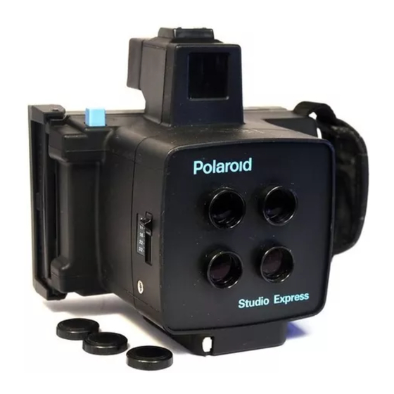
Section I - General Description Camera Capabilities and Applications The Polaroid Model 485B Studio Express is a hand-held or tripod-mounted camera which produces four portraits in color or black-and-white, on a single sheet of Viva film. The four portraits can be all alike, or all four can be different by selectively covering three of the lenses with lens caps each time a new portrait is taken, or the four portraits on a film sheet can be a combination of the above. -
Page 5: Optional Accessories
Optional Accessories • Model 485 Flash Unit with two switch-selectable light output levels, for ISO 80-160 and ISO 3000 films (PID #614528). • Flash Adaptors for 120V (PID #614737) and 220V (PID #614827). • Supplementary Lenses M78V for photography at 177 cm (subject image size will be somewhat smaller than at 122 cm) (PID #614736). -
Page 6: Camera Outline Dimensions
Figure 1-2. Camera outline dimensions... -
Page 7: Section 2 - Operation
Section 2 - Operation Aperture Control and Selection (Figure 2-1) Lens apertures from f/8 to f/32 may be selected using the Aperture Indicator Knob on the right side of the Camera Front Panel. This knob is attached to the Click Plate, which slides beneath the Guide Plate. Small steel balls seated in holes in the Click Plate create detents at the five f/stop positions. -
Page 8: Shutter Operation And Flash Synchronization
Shutter Operation and Flash Synchronization Overall Summary The Shutter operates mechanically, first rotating a Light Interception Blade, then a Shutter Blade (Figure 2-2). The Light Interception Blade uncovers Baseplate openings in line with the lenses. The Shutter Blade then exposes the film as its openings sweep past the Baseplate openings. -
Page 9: Detailed Operation
Detailed Operations Pressing the Shutter Button pivots the Release Lever and Pressure Lever, rotating the Light Interception Blade (Figure 2-3). Although the Light Interception Blade ears no longer block the Baseplate openings, no exposure occurs because the Shutter Blade remains latched. (Figure 3-12 in Section 3 shows the left and Right Hooks engaging the Shutter Blade driving Wheel, resulting in this latching action.) Release Lever... -
Page 10: Shutter Blade Unlatching Action
Release Lever Pressure Lever Shutter Blade Wheel (Spring-coupled to Pressure Lever) Figure 2-4. Shutter blade unlatching action To synchronize flash circuit firing with the instant of maximum shutter opening, the Wheel driving the Shutter Blade has a cam lobe on its lower edge (Figure 2-5). Normally-Open Contacts Wheel Wheel Latched... -
Page 11: Four-Frame Exposure
actuated when the Shutter Button is depressed is wired in series with the X-Contacts. When the Shutter Button is released, the Microswitch opens the circuit before the X- Contacts are closed a second time by the cam lobe. (Also see Figures 3-19 and 3-20 in Section 3.) Four-Frame Exposure Each release of the Shutter on a Model 485B Studio Express Camera allows light from... -
Page 12: Section 3 - Disassembly And Reassembly
Section 3 - Disassembly and Reassembly Required Tools and Materials • Phillips head driver bit #U51B, magnetized. • Wooden chuck #U51, to hold driver bit #U51B. • Thin-blade “stiletto” style tool. • Flat blade jeweler’s screwdrivers. • Small tweezers or forceps. •... -
Page 13: Replacing Lenses, Tape Measure, Shutter And Aperture Assemblies
5. Now remove four screws holding Shutter and Aperture Assemblies to Camera Body. Access to these four screws is through holes “a” in the Lens Board (Figure 3-1). 6. Partially lift Front Panel holding the Shutter and Aperture Assemblies off Camera Body untiltwo-part connector from Hot Shoe wires is accessible on the right side. -
Page 14: Removing Camera Back, Backplate And Hand Strap
Removing Camera Back, Backplate (Holder Frame) and Hand Strap (Figure 3-2) 1. Unlatch and open the Camera Back. Remove the eight screws mounting the Camera Back to the Backplate (Holder Frame). Camera Back Back Plate Figure 3-2. Removing camera back 2. -
Page 15: Replacing Camera Back, Backplate And Hand Strap
Replacing Camera Back, Backplate (Holder Frame) and Hand Strap Note: To reassemble or replace parts and sub-assemblies, do the Disassembly or Removal steps in reverse order, unless noted otherwise. Disassembling/Reassembling of Sub-Assemblies Viewfinder and Hot Shoe (Figures 3-4 through 3-6) Notes: •... -
Page 16: Removing Viewfinder Object Frame
Viewfinder Cover Release tab here with thin blade Locking Tab Slot Object Frame Locking Tab Metal Post Lip on Tab Camera Body Figure 3-4. Removing viewfinder object frame 4. Now free the Viewfinder Cover by removing two screws A and the nut plate at rear, then the two screws B at the front of the Cover (Figure 3-5). -
Page 17: Removing Viewfinder Cover And Lens
Eyecup Viewfinder Cover Eyepiece Lens Object Frame Slot Bright Frame Object Lens 2 Object Lens 1 Nut Plate Slot Tape Figure 3-5. Removing Viewfinder Cover and Lenses 8. If the Hot Shoe or its electrical connections need servicing, disassemble the Hot Shoe as follows: (Figure 3-6) •... -
Page 18: Flash Hot Shoe Disassembly
Plate Spring Hot Shoe Clip Hot Shoe Lift here to Base release lip Viewfinder Cover Nut Plate Tape Figure 3-6. Flash hot shoe disassembly... -
Page 19: Shutter Release Button
Shutter Release Button (Figure 3-7) Note: Camera Back and Backplate must first be removed. (Refer to the Removing/ Replacing procedure in this Section.) 1. Unhook the lower end of the Spring from the Release Lever Sub-assembly tab. 2. Remove two screws A securing Counter Plat: lift off the Counter Plate with the Spring attached. -
Page 20: Aperture Mechanism
Aperture Mechanism Aperture Blades ( Figures 3-8 and 3-9) 1. Remove the Portrait Lenses and Decoration Plate. Refer to Removing Lenses, Tape Measure, Shutter and Aperture Assemblies, steps 1 and 2 in this Section. 2. Remove the Lens Board by removing four mounting screws A (Figure 3-8). 3. -
Page 21: Guide Plate, Click Plate Or Aperture Lever
Guide Plate, Click Plate or Aperture Lever (Figure 3-10) 1. Remove the Lenses, Decoration Plate, Lens Board, Selector Board and Aperture Indicator Knob (See steps 1-4 in the preceding Aperture Blade procedure). 2. Remove the Guide Plate by removing its four mounting screws A. Caution Remove carefully to prevent loss of steel balls! 3. -
Page 22: Aperture Mechanism Blade-Actuating Parts
Guide Plate Steel Balls Click Plates Aperture Lever Sub-Assy Aperture Spring E-ring Poly Slider (Bearing) Aperture Plate Sub-Assy Aperture Blades Figure 3-10. Aperture mechanism blade-actuating parts... -
Page 23: Aperture And Shutter Mechanisms From The Front Panel
Aperture and Shutter Mechanisms from the Front Panel 1. Remove the Front Panel containing the Aperture and Shutter Mechanisms from the Camera Body (See steps in preceding Removing and Replacing Lenses, Tape Measure, Shutter and Aperture Assemblies procedure). 2. Remove the Lens Board by removing four screws A (Figure 3-11). 3. -
Page 24: Shutter Mechanism
Shutter Mechanism Note: Before performing any of the following steps, first remove from the Camera Body theFront Panel, which contains the Shutter and Aperture Mechanisms (See steps 1 - 7 in preceding Removing and Replacing Lenses, Tape Measure, Shutter and Aperture Assemblies procedure). Next, remove the Lens Board and Selector Board from the Aperture Mechanism side of the Front Panel (See step 2 and 3 in preceding Aperture and Shutter Mechanisms from the Front Panel procedure and Figure 3-11). -
Page 25: Shutter Blade Positions
4. Carefully lift off the Shutter Board Sub-assembly, using care not to disturb the position of the two Shutter Blades A and B beneath the Sub-Assembly (Figure 3-13). Caution Before removing the Shutter Blades, note their order and orientation to assure correct placement when reinstalling. -
Page 26: Shutter Mechanism Sub-Assemblies
Shutter Mechanism Sub-Assemblies (Figures 3-14 through 3-17) 1. Release Slide Assembly • Remove screws, bushings, teflon washers, release slide and second set of teflon washers. • Re-assembly, use Loctite under screw heads. Release Slide Washers Bushings Screws Figure 3-14. Release slide assembly 2. -
Page 27: Microswitch
3. Microswitch • Unsolder black and blue leads, remove two Switch mounting screws and washers. If necessary, remove Switch Plate by removing its two mounting screws. • Re-assemble in reverse order. If Switch Plate has been disturbed, temporarily remount it with rough side up, then mount Switch on Plate and resolder wire leads. -
Page 28: Shutter Drive: Release Lever, Pressure Lever And Wheel Assembly
• Finally, Remove the Wheel sub-assembly by removing the E-Ring and teflon washer (Poly-Slider) on its pivot pin. • Reassemble in the reverse order. Note the following: Place the center coil of the Release Lever Spring over the Pressure center post (plain end to the left, resting against the underside of the Release Lever pivot post, loop end to the right, hooked over the Pressure Lever. -
Page 29: Adjusting Flash Synchronization Contacts
Adjusting Flash Synchronization Contacts Synchro (X) Switch Contacts A and B should be normally open when no shutter action occurs, and close momentarily when the Shutter is operated. This can be checked by placing your index finger on the Wheel pin to prevent it from rotating, as the Shutter Release Button is slowly depressed. -
Page 30: Wiring Connections And Schematic
Wiring Connections and Schematic Interconnection of the Body Connector, Synchro (X) Switch, Microswitch and X-Sync Connector, and wire colors, are shown in Figure 3-19. Figure 3-20 is a schematic representation, depicting the function of the Microswitch to prevent flash firing a second time as the Shutter blades close. Microswitch Body Connector X (Synchro) Contacts... -
Page 31: Camera Troubleshooting Guide
Troubleshooting Guide Problem Possible Causes Solution Shutter does not release. • Shutter Button does not • Check mechanism for jams. move. • Spring loose/broken. • Wheel does not unlatch. • Pressure Lever jammed. • Mechanism broken. Shutter Blades dirty. Shutter speed low, film is • See Causes above. See Solutions above.
Need help?
Do you have a question about the Miniportrait 485B and is the answer not in the manual?
Questions and answers