Polaroid Miniportrait 203 Repair Manual
Hide thumbs
Also See for Miniportrait 203:
- User manual (19 pages) ,
- Troubleshooting manual (18 pages) ,
- User manual (19 pages)

Related Manuals for Polaroid Miniportrait 203


Summary of Contents for Polaroid Miniportrait 203
- Page 1 Repair Manual Miniportrait 203 September 1996 Americas Business Center Technical Services 201 Burlington Road Bedford MA 01730 TEL: 1.781.386.5309 FAX: 1.781.386.5988...
-
Page 2: Table Of Contents
Camera Schematic Diagram ................List of Illustrations Figure Page Miniportrait 203 Appearance and Typical Photos ........Miniportrait 203 Overall Dimensions ............. 203 Minportrait Shutter and Light Interception blades ......Mode Change Lever Set at Single Frame ..........Mode Change Lever Moves to New Position ......... - Page 3 IMPORTANT Many of the parts, mechanisms and circuits of the 203 Miniportrait Camera are identical to those in the 403 Miniportrait. This Manual covers only the 203 parts and repairs that are different from the 403. These differences include: • Shutter Blade •...
-
Page 4: Section 1 - Camera Appearance And Dimensions
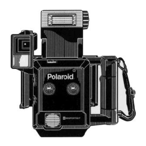
Section 1 - Appearance and Dimensions Figure 1. Miniportrait 203 appearance and typical photos (Produces two identical or two different photos per film sheet) -
Page 5: Miniportrait 203 Overall Dimensions
Figure 2. Miniportrait 203 overall dimensions... -
Page 6: Section 2 - Operation
Section 2 - Operation Exposure Modes (Shutter and Light Interception Blades) The Miniportrait Model 203 has two exposure modes: single (half- frame) exposure allowing two different portraits on a single sheet of film, and dual exposure allowing a pair of identical portraits on a sheet of film. Accordingly, as shown in Figure 3 the shape of the Shutter Blade (A) and Light Interception Blade (B) in the 203 are different from those in the Miniportrait 403. -
Page 7: Single (Half-Frame) Exposure Operation
Single (Half-Frame) Exposure Operation When Mode Change Lever (1) (Figure 4) is set at single-frame, after the Shutter has been charged, levers (2) and (3) move a second forked Mode Change Lever (4) toward the Motor. Mode Change Lever (4) is set so that pin (a) rests in its forked slot. Figure 4. -
Page 8: Closing Aperture
When the Shutter is released and the Motor runs, pin (b) rotates one-half turn, moving the forked lever (4) in the arrow direction shown in Figure 6. This causes pin (b) to rotate the Light Interception Blade (5), closing the aperture. Figure 6. -
Page 9: Dual-Frame Exposure Operation
Dual-Frame Exposure Operation In the dual-frame exposure mode, lever (1) is held in a neutral position by the spring “A.” This allows the Light Interception Blade to be set in the position shown in Figure 7. Now, as the Motor runs, pin (a) rotates clockwise as the arrows indicate. However, pin (a) does not turn the Mode Change Lever because it is not engaged in the Lever slot. -
Page 10: Section 3 - Reassembly Of Exposure Mode Change Gears
Section 3 - Reassembly of Exposure Mode Change Gears Note: Disassembly procedures are basically similar for both the 203 and 403 Miniportrait Cameras. See Section 3 of the Miniportrait 403 Repair Manual. 1. Remove Gear 1 and turn Gear (2) until tip A of the switch contact aligns with the third tooth of Gear (2). - Page 11 3. Next, set the Mode Change Lever in the position for single- frame exposure. Now turn Gear (1) past the Switch contact, within the cam groove C range (Figure 9). The Light Interception Blade should now cover the aperture. Figure 9. Setting positon of mode change lever for single frame exposure 4.
-
Page 12: Section 4 - Circuit Diagrams, Board Layouts, Component Lists
Section 4 - Circuit Diagrams, Board Layouts and Component Lists... -
Page 13: Main Pc Board
Note: Interchangeable with 403 Configuration C or higher. Figure 10. Main PC board (Part No. 159 01021) -
Page 14: Main Pc Board
Table 1. Main PC board components... -
Page 15: Sonar Pc Board
Note: Sonar PC Board 158 05011 can be used in 203 Miniportrait Cameras below Configuration D, and in 403 Miniportrait Cameras below Configuration C. Future Sonar PC Board 158 05021 will be usable in any 203 or 403 of any Configuration code. Figure 11. -
Page 16: Sonar Pc Board
Table 2. Sonar PC board components... -
Page 17: Electronic Flash Pc Board
Sub Board Part No. E 31016 932 Main Board Part No. E 31016 902 Figure 12. Electronic Flash PC board... -
Page 18: Electronic Flash Pc Board
Table 3. Electronic flash PC board components... -
Page 19: Camera Wiring Diagram
Figure 13. Camera wiring diagram... -
Page 20: Camera Schematic Diagram
Figure 14. Camera schematic diagram...
Need help?
Do you have a question about the Miniportrait 203 and is the answer not in the manual?
Questions and answers