Advertisement
Available languages
Available languages
Quick Links
LI 22HS
LI 26HS
Luft/Wasser-
Wärmepumpe für
Innenaufstellung
Bestell-Nr. / Order no. / N
Air-to-Water
Heat Pump for
Indoor Installation
o
de commande : 452158.66.09
Montage- und
Gebrauchsanweisung
Installation and
Operating Instructions
Instructions d'installation
et d'utilisation
Pompe à chaleur
air-eau pour
installation
intérieure
FD 8610
Advertisement
Chapters

Related Manuals for Dimplex LI 22HS


Summary of Contents for Dimplex LI 22HS
- Page 1 LI 22HS LI 26HS Montage- und Gebrauchsanweisung Installation and Operating Instructions Instructions d’installation et d’utilisation Luft/Wasser- Air-to-Water Pompe à chaleur Wärmepumpe für Heat Pump for air-eau pour Innenaufstellung Indoor Installation installation intérieure Bestell-Nr. / Order no. / N de commande : 452158.66.09...
-
Page 3: Table Of Contents
Reinigung / Pflege ........................D-7 8.1 Pflege..............................D-7 8.2 Reinigung Heizungsseite ........................D-7 8.3 Reinigung Luftseite ..........................D-8 Störungen / Fehlersuche ......................D-8 10 Außerbetriebnahme / Entsorgung ....................D-8 11 Geräteinformation ........................D-9 12 Garantieurkunde......................... D-10 Anhang / Appendix / Annexes ......................A-I www.dimplex.de... -
Page 4: Bitte Sofort Lesen
Bitte sofort lesen Verwendungszweck der Wärmepumpe 1.1 Wichtige Hinweise 2.1 Anwendungsbereich ACHTUNG! Die Wärmepumpe darf beim Transport nur bis zu einer Neigung von 45° Die Hochtemperatur-Luft-Wasser-Wärmepumpe ist für die Sa- (in jeder Richtung) gekippt werden. nierung bestehender Heizungsanlagen einsetzbar, wenn Vor- lauftemperaturen bis 75 °C erforderlich sind. -
Page 5: Lieferumfang
Warmwasserbereitung und die sicherheitstechnischen Einrich- tungen. Der bauseits anzubringende Außentemperaturfühler incl. Befes- tigungsmaterial liegt dem Regler bei. Funktionsweise und Handhabung des Wärmepumpenreglers sind in der dazu beiliegenden Gebrauchsanweisung beschrie- ben. Verdampfer Rückschlagventil Ventilator Schaltkasten Pressostate Verflüssiger Filtertrockner Verdichter R404A Verdichter R134a www.dimplex.de... -
Page 6: Transport
Transport Aufstellung ACHTUNG! 5.1 Allgemein Die Wärmepumpe darf beim Transport nur bis zu einer Neigung von 45° (in jeder Richtung) gekippt werden. Das Gerät ist grundsätzlich in Innenräumen auf einer ebenen, glatten und waagrechten Fläche aufzustellen. Dabei sollte der Der Transport zum endgültigen Aufstellungsort sollte mit Holz- Rahmen rundum dicht am Boden anliegen, um eine geeignete rost erfolgen. -
Page 7: Montage
Anschlussstutzen an der Ansaug- und Ausblasseite des Ver- dampfers mit 4 Sechskantschrauben M8x16 an den vorgesehe- nen Gewindelöchern befestigt. Dabei ist zu beachten, dass beide Luftkanalstutzen nur mit der Isolierung und nicht mit dem Außen- blech in Berührung kommen. www.dimplex.de... -
Page 8: Elektrischer Anschluss
Inbetriebnahme Frostschutz Bei Wärmepumpen, die frostgefährdet aufgestellt sind, sollte eine manuelle Entleerung (siehe Bild) vorgesehen werden. So- 7.1 Allgemein fern Regler und Heizungsumwälzpumpe betriebsbereit sind, ar- beitet die Frostschutzfunktion des Reglers. Bei Außerbetrieb- Um eine ordnungsgemäße Inbetriebnahme zu gewährleisten, nahme der Wärmepumpe oder Stromausfall ist die Anlage zu sollte diese von einem vom Werk autorisierten Kundendienst entleeren. -
Page 9: Reinigung / Pflege
Danach muss mit geeigneten neutralisierenden Mitteln gründlich nachgespült werden, um Beschädigungen durch eventuell im System verbliebene Reinigungsmittelreste zu verhindern. Die Säuren sind mit Vorsicht anzuwenden und es sind die Vor- schriften der Berufsgenossenschaften einzuhalten. Im Zweifelsfall ist mit dem Hersteller des Reinigungsmittels Rücksprache zu halten! www.dimplex.de... -
Page 10: Reinigung Luftseite
10 Außerbetriebnahme / 8.3 Reinigung Luftseite Entsorgung Luftkanäle, Verdampfer, Lüfter und Kondensatablauf sind vor der Heizperiode von Verunreinigungen (Blätter, Zweige usw.) zu rei- nigen. Dazu ist die Wärmepumpe an der Frontseite zuerst unten Bevor die Wärmepumpe ausgebaut wird, ist die Maschine span- und dann oben zu öffnen. -
Page 11: Geräteinformation
11 Geräteinformation Geräteinformation für Luft/Wasser-Heiz-Wärmepumpen Typ- und Verkaufsbezeichnung LI 22HS LI 26HS Bauform Schutzart nach EN 60 529 für Kompaktgerät bzw. Heizteil IP 21 IP 21 Aufstellungsort Innen Innen Leistungsangaben Temperatur-Betriebseinsatzgrenzen: bis 75 / ab 18 bis 75 / ab 18 Heizwasser-Vorlauf / -Rücklauf... -
Page 12: Garantieurkunde
Teile ersetzt werden. Durch Art oder Ort des Einsatzes des Systemtechnik-Kundendienst erfahren Sie über die zentrale Ser- Gerätes oder schlechte Zugänglichkeit des Gerätes bedingte au- vicehotline der Glen Dimplex Deutschland GmbH. ßergewöhnliche Kosten der Mängelbeseitigung werden nicht übernommen. Der freie Gerätezugang muss durch den Endab- Glen Dimplex Deutschland GmbH nehmer gestellt werden. - Page 13 Maintenance / Cleaning ........................E-7 8.1 Maintenance ............................E-7 8.2 Cleaning the Heating System ......................... E-7 8.3 Cleaning the Air System ......................... E-7 Faults / Trouble-Shooting ......................E-8 10 Decommissioning/Disposal ......................E-8 11 Device Information ........................E-9 Anhang / Appendix / Annexes ......................A-I www.dimplex.de...
-
Page 14: Please Read Immediately
Please Read Purpose of the Heat Immediately Pump 1.1 Important Information 2.1 Application The high temperature air-to-water heat pump can be used for ret- ATTENTION! rofitting existing heating systems when flow temperatures of up When transporting the heat pump, ensure that it is not tilted more than to 75 °C are required. -
Page 15: Scope Of Delivery
The enclosed operating instructions describe the function and use of the heat pump controller. Evaporator Check valve Ventilator Switch box Pressure switches Liquifier Filter dryer R404A compressor R134a compressor www.dimplex.de... -
Page 16: Transport
Transport Set-up ATTENTION! 5.1 General Information When transporting the heat pump, ensure that it is not tilted more than 45° (in any direction). The unit must be installed indoors on a level, smooth and hori- zontal surface. The entire base of the frame should lie directly on Use a wooden pallet for transporting the heat pump to the final in- the floor to ensure a good soundproof seal. -
Page 17: Installation
4 M8 x 16 hexagon bolts in the threaded holes provided. When doing this, ensure that both air duct stubs only touch the insula- tion. There should be no contact with the external sheeting. www.dimplex.de... -
Page 18: Electrical Connection
Start-Up Antifreeze A method of manual drainage (see illustration) should be pro- vided for heat pumps which are exposed to frost. The antifreeze 7.1 General Information function of the heat pump controller is active whenever the con- troller and the heat circulating pump are ready for operation. If To ensure that start-up is performed correctly, it should only be the heat pump is taken out of service or in the event of a power carried out by an after-sales service technician authorised by the... -
Page 19: Maintenance / Cleaning
In the event that op- Chapter 4. erating malfunctions due to contamination still occur, the system To prevent the evaporator and the condensate tray from being should be cleaned as described below. damaged, do not use hard or sharp objects for cleaning. www.dimplex.de... -
Page 20: Faults / Trouble-Shooting
Faults / Trouble- 10 Decommissioning/ Shooting Disposal This heat pump is a quality product and is designed for trouble- Before removing the heat pump, disconnect it from the power free and maintenance-free operation. In the event that a fault source and close all valves. Observe all environmentally-relevant should occur, it will be indicated on the heat pump manager dis- requirements regarding the recovery, recycling and disposal of play. -
Page 21: Device Information
11 Device Information Device information for air-to-water heat pumps for heating purposes Type and order code LI 22HS LI 26HS Design Degree of protection according to EN 60 529 for compact devices IP21 IP21 and heating components Installation Location Indoors... - Page 22 Table des matières A lire immédiatement ! ......................... F-2 1.1 Remarques importantes.......................... F-2 1.2 Dispositions légales et directives ......................F-2 Utilisation de la pompe à chaleur....................F-2 2.1 Domaine d’utilisation..........................F-2 2.2 Fonctionnement ............................F-2 Fourniture ............................F-3 3.1 Appareil de base ............................. F-3 3.2 Boîtier électrique .............................
-
Page 23: Lire Immédiatement
Les enfants doivent être surveillés pour éviter qu'ils ne jouent avec l'appareil. www.dimplex.de... -
Page 24: Fourniture
Fourniture 3.2 Boîtier électrique Le boîtier électrique est monté dans la pompe à chaleur. Le boî- 3.1 Appareil de base tier électrique peut être rabattu après avoir retiré l’habillage fron- tal inférieur et dévissé la vis de fixation se trouvant en haut à La pompe à... -
Page 25: Transport
à chaleur au sys- tème de chauffage à l'aide d’un tuyau flexible. Les conduits d’air utilisés doivent être découplés de la pompe à chaleur d’un point de vue acoustique pour éviter les transmis- sions de bruit sur les conduits. www.dimplex.de... -
Page 26: Montage
Montage 6.1 Remarques d’ordre général Les raccordements suivants doivent être réalisés sur la pompe à chaleur : Aspiration/évacuation d’air Circuits départ et retour de l’installation de chauffage Ecoulement des condensats Câble de commande vers régulateur de pompe à chaleur Alimentation électrique 6.2 Prise d’air ATTENTION ! Les canaux d’aspiration et d’évacuation d'air ne doivent être ni rétrécis,... -
Page 27: Branchements Électriques
âmes simples (sonde de retour intégrée) au régulateur de pompe à chaleur nécessaire à la commande. Des instructions plus pré- cises se trouvent dans les instructions d'utilisation du régulateur de pompe à chaleur. Pour des informations plus détaillées, cf. schémas électriques en annexe. www.dimplex.de... -
Page 28: Nettoyage / Entretien
Nettoyage / entretien Température Différence de température max. de départ entre circuits départ et retour du 8.1 Entretien chauffage à -20 °C -15 °C Il faut éviter d’appuyer ou de déposer des objets sur l’appareil -14 °C -10 °C afin de protéger la laque. Les parties extérieures de la pompe à -9 °C -5 °C chaleur peuvent être essuyées avec un linge humide et des pro-... -
Page 29: Nettoyage Côté Air
à chaleur. Si vous n'êtes pas en mesure de remédier vous-même au dysfonction- nement, veuillez vous adresser au service après-vente compé- tent. ATTENTION ! Les travaux sur la pompe à chaleur doivent être effectués uniquement par des techniciens qualifiés et agréés. www.dimplex.de... -
Page 30: Informations Sur Les Appareils
11 Informations sur les appareils Informations sur les pompes à chaleur air/eau pour chauffage Désignation technique et commerciale LI 22HS LI 26HS Forme Type de protection selon EN 60 529 pour app. compact ou élt. de chauffe IP 21 IP 21 Emplacement intérieur... - Page 31 Maßbild / Dimension Drawing / Schéma coté ................A-II Diagramme / Diagrams / Diagrammes..................A-III 2.1 Kennlinien / Characteristic Curves / Courbes caractéristiques LI 22HS..........A-III 2.2 Kennlinien / Characteristic Curves / Courbes caractéristiques LI 26HS..........A-IV Stromlaufpläne / Circuit Diagrams / Schémas électriques............A-V 3.1 Steuerung / Control / Commande ......................A-V...
-
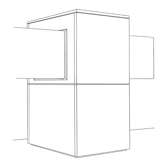
Page 32: Maßbild / Dimension Drawing / Schéma Coté
1 Maßbild / Dimension Drawing / Schéma coté A-II... -
Page 33: Diagramme / Diagrams / Diagrammes
2 Diagramme / Diagrams / Diagrammes 2.1 Kennlinien / Characteristic Curves / Courbes caractéristiques LI 22HS www.dimplex.de A-III... -
Page 34: Kennlinien / Characteristic Curves / Courbes Caractéristiques Li 26Hs
2.2 Kennlinien / Characteristic Curves / Courbes caractéristiques LI 26HS A-IV... -
Page 35: Stromlaufpläne / Circuit Diagrams / Schémas Électriques
3 Stromlaufpläne / Circuit Diagrams / Schémas électriques 3.1 Steuerung / Control / Commande www.dimplex.de... -
Page 36: Last / Load / Charge
3.2 Last / Load / Charge A-VI... -
Page 37: Anschlussplan / Circuit Diagram / Schéma Électrique
3.3 Anschlussplan / Circuit Diagram / Schéma électrique www.dimplex.de A-VII... -
Page 38: Legende / Legend / Légende
3.4 Legende / Legend / Légende Pressostat Abtauende Defrost end controller Pressostat fin de dégivrage Pressostat HGB-Ventil Pressure switch, HGB valve Pressostat vanne HGB Pressostat Hochdruck High-pressure switch Pressostat haute pression Pressostat Hochdruck, 2. Kältekreis High-pressure switch, refrigerating circuit 2 Pressostat haute pression, circuit froid 2 Pressostat Niederdruck Low-pressure switch... -
Page 39: Hydraulische Prinzipschemen / Hydraulic Plumbing Diagram / Schémas Hydrauliques
4 Hydraulische Prinzipschemen / Hydraulic Plumbing Diagram / Schémas hydrauliques 4.1 Monoenergetische Anlage / Mono Energy System / Installation monoénergétique www.dimplex.de A-IX... -
Page 40: Monoenergetische Anlage Und Warmwasserbereitung / Mono Energy System And Domestic Hot Water Preparation / Installation Monoénergétique Et Production D'eau Chaude
4.2 Monoenergetische Anlage und Warmwasserbereitung / Mono Energy System and Domestic Hot Water Preparation / Installation monoénergétique et production d‘eau chaude... -
Page 41: Legende / Legend / Légende
External wall sensor Sonde de paroi extérieure Rücklauffühler Return flow sensor Sonde de retour Warmwasserfühler Hot water sensor Sonde d’eau chaude Elektroverteilung Electrical distribution system Distributeur courant électrique Kaltwasser Cold water eau froide Warmwasser Domestic hot water Eau chaude www.dimplex.de A-XI... -
Page 42: Konformitätserklärung / Declaration Of Conformity / Déclaration De Conformité
5 Konformitätserklärung / Declaration of Conformity / Déclaration de conformité A-XII... - Page 43 A-XIII...
- Page 44 Glen Dimplex Deutschland GmbH Irrtümer und Änderungen vorbehalten. Geschäftsbereich Dimplex Subject to alterations and errors. Am Goldenen Feld 18 Sous réserve d’erreurs et modifications. D-95326 Kulmbach +49 (0) 9221 709 565 www.dimplex.de...
Need help?
Do you have a question about the LI 22HS and is the answer not in the manual?
Questions and answers