Table of Contents
Advertisement
Quick Links
Manual 238-49399-00A
UPDX Series
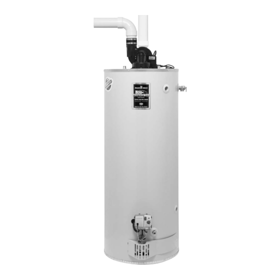
Ultra Low NOx Power Direct Vent
Gas Water Heaters
SERVICE
MANUAL
Troubleshooting Guide
and Instructions for Service
(To be performed ONLY by
qualified service providers)
Models Covered
by This Manual:
UPDX250T*FRN
UPDX265T*FRN
UPDX275T*FRN
UPDX50S50FR*N
UPDX65S55FR*N
UPDX75S55FR*N
(*) Denotes Warranty Years
Save this manual for future reference
Advertisement
Table of Contents

Related Manuals for Bradford White UPDX series


Summary of Contents for Bradford White UPDX series
- Page 1 UPDX Series Ultra Low NOx Power Direct Vent Gas Water Heaters SERVICE MANUAL Troubleshooting Guide and Instructions for Service (To be performed ONLY by qualified service providers) Models Covered by This Manual: UPDX250T*FRN UPDX265T*FRN UPDX275T*FRN UPDX50S50FR*N UPDX65S55FR*N UPDX75S55FR*N (*) Denotes Warranty Years...
-
Page 2: Table Of Contents
Bradford White UPDX Series Ultra Low NOx Power Direct Vent Gas Water Heaters Table of Contents PageUPDX Service Procedure Introduction - - - How to Use This Manual - - - Tool Required for Service - - - Specifications - - -... - Page 3 UPDX Series WARNING CAUTION If the information in these instructions is not followed Incorrect operation of this appliance may exactly, a fire or explosion may result causing property create a hazard to life and property and damage, personal injury, or death.
-
Page 4: Introduction
UPDX Series Introduction The new Bradford White UPDX2 water heaters are designed to provide reliable performance with enhanced standard features. New design features include reliable spark to pilot ignition system, enhanced diagnostics, simplified servicing, significantly quieter operation, additional vent lengths, certified FVIR technology and Ultra Low NOx emissions. -
Page 5: How To Use This Manual
It is intended for this manual to be used by qualified service personnel for the primary purpose of troubleshooting and repair of the Bradford White UPDX Series water heaters. Understanding the sequence of operation section of this manual will contribute greatly to troubleshooting the water heater. -
Page 6: Specifications
UPDX Series Specifications Power supply Dedicated 115VAC, 60 Hz, 15A Gas Supply Pipe Minimum 1/2" NPT (schedule 40 black iron pipe recommended) Approved Gas Type Natural. Unit must match gas type supplied. Gas Pressure 6.0" W.C. min. for Nat gas, 11.0" W.C. min. for L.P. gas, 14.0" W.C. maximum (Nat. & L.P.) - Page 7 Specifications UPDX Series Venting Specifications for: 48 Gallon 65 Gallon 75 Gallon This water heater is approved for installation with the following PVC, CPVC or ABS Schedule 40 venting material. The maximum and minimum vent lengths listed in thistable are for the exhaust portion of the vent.
-
Page 8: Control Timings
Control Timings UPDX Series Control Timings Ignition State Timing Pre-purge 15 Seconds Trial for Ignition 90 Seconds Flame Stabilization Period 3 Seconds Inter-purge 15 Seconds Flame Failure Response Time 1.5 Seconds (2 second maximum; 1 second minimum.) Post-purge 15 Seconds... -
Page 9: Sequence Of Operation
UPDX Series Sequence of Operation Power Up Sequence 1. Start Up. Upon power up, the control runs a safe-start check with a typical start-up delay of 1-5 seconds. 2. Flammable Vapor Check. To assure no outputs are energized if the “Flammable Vapor Sensor” is out of range, the control will test the “Flammable Vapor Sensor”... - Page 10 UPDX Series Sequence of Operation Normal Heating Sequence (continued) 7. Steady State Operation. During steady state operation the gas control monitors: Thermostat Temperature Sensor- When the setpoint temperature is satisfied, the gas control is shut down and the blower will post purge for 15 seconds. The gas control LED flashes a short flash once every 4 seconds (idle) status code.
- Page 11 UPDX Series Sequence of Operation Abnormal Operation (cont.) 3. Pressure Switch/Blower Temperature Fault: a) Pressure Switch Closed at Start of Call for Heat - The gas control waits 4 seconds then, proceeds to flash 2 times followed by a 3 second pause. The gas control waits 2 minutes and then turns on the blower for 30 seconds.
-
Page 12: Troubleshooting
Troubleshooting UPDX Series Green LED Indicator Observe green LED indicator on gas control. Error flash codes are displayed with a three second pause before repeating. Check and repair the system as noted in the troubleshooting table below. (For models with serial numbers starting with K or later see chart on page 15.) - Page 13 UPDX Series Troubleshooting Service LED Status Control Status Probable Cause Procedure 1. Unstable pilot. 2. Pilot tube blocked or restricted. Six-one flash, three Failed to light pilot. 1-4. Page 18 3. Oxidation build up on pilot electrode. second pause System auto resets.
- Page 14 UPDX Series Troubleshooting Green LED Indicator Observe green LED indicator on Electronic gas control. Error flash codes are displayed with a three second pause before repeating. Check and repair the system as noted in the troubleshooting table below. (The following chart is for models with serial numbers starting with K or later.)
- Page 15 UPDX Series Troubleshooting Service LED Status Control Status Probable Cause Procedure 1. Unstable pilot. 2. Pilot tube blocked or restricted. Six-one flash, three Failed to light pilot. 1-4. Page 18 3. Oxidation build up on pilot electrode. second pause System auto resets.
-
Page 16: Burner Inspection, Cleaning And Replacement
Under no circumstances shall flammable materials be used or stored in the vicinity of the water heater. With the inner door removed the Bradford White Defender Safety System will be deactivated. If flammable vapors are present, a fire or explosion may result causing property damage, personal injury or death. - Page 17 UPDX SERVICE PROCEDURE I UPDX Series Burner Operation Inspection, Cleaning and Replacement Burner Cleaning (Continued) Step 4. Disconnect (unscrew) feedline from the main burner door. Main Burner Door Feedline Step 5. Remove main burner orifice from feed line (3/8" wrench). Inspect and...
- Page 18 UPDX SERVICE PROCEDURE II UPDX Series Pilot Inspection, Cleaning and Replacement Pilot assembly Inspection, Cleaning and Replacement Gas Control shown in the “OFF” Position Step 1. Position gas control power switch to the “OFF” position and unplug heater from wall outlet.
-
Page 19: Pressure Switch Testing And Replacement
UPDX SERVICE PROCEDURE III UPDX Series Pressure Switch Testing and Replacement Pressure Switch Testing WARNING 115 volt potential exposure. Use caution Step 1. Position gas control power switch making voltage checks to avoid personal injury. to the “OFF” position. Step 2. - Page 20 UPDX SERVICE PROCEDURE III Pressure Switch Testing and UPDX Series Replacement Pressure Switch Replacement WARNING 115 volt potential exposure. Use caution Step 1. Position gas control power switch to avoid personal injury. to the “OFF” position. Gas Control shown in the Step 2.
-
Page 21: Blower Testing And Replacement
UPDX SERVICE PROCEDURE IV UPDX Series Blower Testing and Replacement WARNING Blower Testing Gas Control shown in 115 volt potential exposure. Use caution when the “ON” Position Step 1. Position gas control power making voltage checks to avoid personal injury. -
Page 22: Blower Removal
UPDX SERVICE PROCEDURE IV UPDX Series Blower Testing and Replacement Gas Control shown in the Blower Removal “OFF” Position Step 1. Position gas control power switch to the “OFF” position. Step 2. Unplug blower power cord from wall outlet. Step 3. -
Page 23: Blower Temperature Switch Testing And Replacement
UPDX SERVICE PROCEDURE V Blower Temperature Switch Testing UPDX Series and Replacement Blower Temperature Switch WARNING Testing 115 volt potential exposure. Use caution to avoid personal injury. Step 1. Position gas control power switch Gas Control shown in the “OFF”... - Page 24 UPDX SERVICE PROCEDURE V Blower Temperature Switch Testing UPDX Series and Replacement Blower Temperature Switch WARNING 115 volt potential exposure. Use caution Replacement to avoid personal injury. Gas Control shown in the “OFF” Step 1. Position gas control power switch to the “OFF”...
-
Page 25: Thermal Well Testing
UPDX SERVICE PROCEDURE VI UPDX Series Gas Control/Thermal Well Testing and Replacement Gas Control shown in the Gas Control Testing “OFF” Position This section is for models with serial Numbers starting with “K” or earlier. See page 34 for gas control input &... -
Page 26: Determine Water Temperature Inside Tank
UPDX SERVICE PROCEDURE VI Gas Control/Thermal Well Testing and UPDX Series Replacement WARNING Stored water may be HOT when performing the following steps in this procedure. Take necessary precaution to prevent personal injury. Determine Water Temperature Inside Tank Note: It is important to understand once the resistance for the thermal well is determined from page 25, water flow through the heater should not occur. - Page 27 UPDX SERVICE PROCEDURE VI Gas Control & Thermal Well Testing UPDX Series and Replacement Gas Control & Thermal Well Removal From Water Heater Step 1. Position gas control power switch to the “OFF” Gas Control shown in position and Unplug Heater from power supply.
- Page 28 UPDX SERVICE PROCEDURE VI Gas Control & Thermal Well Testing UPDX Series and Replacement Gas Control Assembly to Thermal Well Step 1. Install threaded end of thermal well into tank. Be sure thermal well flange is positioned as shown in photo 27 for proper control alignment.
- Page 29 UPDX SERVICE PROCEDURE VII UPDX Series Brass Well (WV4460) to Polymer Well (WV4462) Gas Control Replacement Brass Well (WV4460) to Polymer Well (WV4462) Gas Control Replacement Step 1. Position gas control power switch to the “OFF” Gas Control shown in position and unplug heater from power supply.
-
Page 30: Brass Well (Wv4460) To Polymer Well (Wv4462
UPDX SERVICE PROCEDURE VII UPDX Series Brass Well (WV4460) to Polymer Well (WV4462) Gas Control Replacement Brass Well (WV4460) to Polymer Well (WV4462) Gas Control Replacement (Continued) Flammable Vapor Sensor Harness Leads Step 9. Connect new flammable vapor sensor harness leads into the flammable vapor sensor. -
Page 31: Gas Control Replacement
UPDX SERVICE PROCEDURE VIII UPDX Series Gas Control Testing and Replacement Gas Control Replacement Step 1. Rotate knob of the gas control to the “OFF” position. Step 2. Turn off gas supply to water heater. Step 3. Disconnect gas supply line from gas control. -
Page 32: Flammable Vapor Sensor Testing
UPDX SERVICE PROCEDURE IX UPDX Series Flammable Vapor Sensor Testing Flammable Vapor Sensor Testing Step 1. Position gas control power switch to Gas Control shown in the “OFF” Position the “OFF” position. Step 2. Disconnect flammable vapor sensor from gas control. -
Page 33: Safety Circuit Voltage Trace
UPDX SERVICE PROCEDURE X UPDX Series Safety Circuit Voltage Trace Safety Circuit Voltage WARNING 115 volt potential exposure. Use caution Trace making voltage checks to avoid personal injury. NOTE: This procedure assumes a cool tank. Step 1. Remove three screws (Phillips... -
Page 34: 115Vac Circuit Trace
UPDX SERVICE PROCEDURE XI UPDX Series 115 VAC Trace WARNING 115 VAC Circuit Trace 115 volt potential exposure. Use caution making voltage checks to avoid personal injury. Step 1. Verify 115VAC and proper polarity at wall outlet. Step 2. With unit plugged in and gas control power switch to the “ON”... -
Page 35: Dip Tube Inspection And Replacement
UPDX SERVICE PROCEDURE XII Dip Tube UPDX Series Inspection and Replacement Dip Tube Inspection and Replacement WARNING Water Heater components and stored water may be HOT when performing the following steps in this procedure. Take necessary precaution to prevent personal injury. -
Page 36: Anode Inspection And Replacement
UPDX SERVICE PROCEDURE XIII Anode UPDX Series Inspection and Replacement Anode Inspection and Replacement WARNING Water Heater components and stored water may be HOT when performing the following steps in this procedure. Take necessary precaution to prevent personal injury. Gas Control shown in the Step 1. -
Page 37: Flue Baffle Inspection And Replacement
UPDX SERVICE PROCEDURE XIIV Flue Baffle UPDX Series Inspection and Replacement Flue Baffle Inspection and Gas Control shown in the “OFF” position Replacement Step 1. Position gas control power switch to the “OFF” position and unplug blower from wall outlet. - Page 38 UPDX SERVICE PROCEDURE XV Inner Door/Gasket Removal, Inspection UPDX Series Replacement and Reinstallation Inner Door Removal Procedure Gas Control shown in the “OFF” position Step 1. Position gas control power switch to the “OFF” position Step 2. Unplug the water heater from the wall outlet Step 3.
- Page 39 UPDX SERVICE PROCEDURE XV UPDX Series Inner Door/Gasket Removal, Inspection Replacement and Reinstallation Inner Door Gasket Replacement Procedure. WARNING If the information in these instructions is not followed exactly, a fire or explosion may result causing property damage, personal injury or death.
- Page 40 UPDX SERVICE PROCEDURE XV Inner Door/Gasket Removal, Inspection UPDX Series Replacement and Reinstallation Installation of Inner Door Position Fiberglass Sock With Gasket (Continued) Step 15. Position the fiberglass sock containing the igniter wire against burner door flange gasket. Step 16.
- Page 41 Bradford White or the supplier of the water heater for information about ordering the optional concentric vent terminal. Bradford White has also developed an air intake relief device that can be installed in the air intake near the water heater temporarily enabling the water heater to operate with a frozen intake terminal.
-
Page 42: Glossary Of Terms
Glossary of Terms UPDX Series British Thermal Units Gallons per Minute Hertz Kilo-watt hour Light Emitting Diode National Pipe Thread Ohms Ohms (resistance) Pounds per Square Inch Revolutions per Minute Energy Cut Out Volts Alternating Current W.C. Inches of Water Column °C... -
Page 43: Parts List
Parts List UPDX Series 15. Cold Water Inlet Diptube 29. Flammable Vapor Sensor 40. Polymer well Gas Control 1. Blower Assembly 16. Flue Baffle 30. Sensor Harness (models with serial numbers 2. Blower Temp. Switch starting with “K” or later) 31.