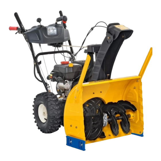
Cub Cadet 524 SWE Operator's Manual
Two-stage snow thrower
Hide thumbs
Also See for 524 SWE:
- User manual ,
- Operator's manual (28 pages) ,
- Illustrated parts list (12 pages)
Advertisement
Safe Operation Practices • Set-Up • Operation • Maintenance • Service • Troubleshooting • Warranty
O
'
M
peratOr
s
anual
Two-Stage Snow Thrower — 524 SWE
WARNING
READ AND FOLLOW ALL SAFETY RULES AND INSTRUCTIONS IN THIS MANUAL
BEFORE ATTEMPTING TO OPERATE THIS MACHINE.
FAILURE TO COMPLY WITH THESE INSTRUCTIONS MAY RESULT IN PERSONAL INJURY.
CUB CADET LLC, P.O. BOX 361131 CLEVELAND, OHIO 44136-0019
Printed In USA
Form No. 769-03344
(July 10, 2007)
Advertisement
Table of Contents

Related Manuals for Cub Cadet 524 SWE


Summary of Contents for Cub Cadet 524 SWE
- Page 1 READ AND FOLLOW ALL SAFETY RULES AND INSTRUCTIONS IN THIS MANUAL BEFORE ATTEMPTING TO OPERATE THIS MACHINE. FAILURE TO COMPLY WITH THESE INSTRUCTIONS MAY RESULT IN PERSONAL INJURY. CUB CADET LLC, P.O. BOX 361131 CLEVELAND, OHIO 44136-0019 Printed In USA Form No. 769-03344...
-
Page 2: Table Of Contents
Visit us on the web at www.cubcadet.com ◊ Call a Customer Support Representative at (800) 965-4CUB ◊ Locate your nearest Cub Cadet Dealer at (877) 282-8684 ◊ Write us at Cub Cadet LLC • P.O. Box 361131 • Cleveland, OH • 44136-0019... -
Page 3: Safe Operation Practices
Important Safe Operation Practices WARNING! This symbol points out important safety instructions which, if not followed, could endanger the personal safety and/or property of yourself and others. Read and follow all instructions in this manual before attempting to operate this machine. Failure to comply with these instructions may result in personal injury. - Page 4 Safe Handling of Gasoline Never run an engine indoors or in a poorly ventilated area. Engine exhaust contains carbon monoxide, an odorless To avoid personal injury or property damage use extreme care and deadly gas. in handling gasoline. Gasoline is extremely flammable and the Do not operate machine while under the influence of vapors are explosive.
-
Page 5: Maintenance & Storage
Maintenance & Storage Do not modify engine Never tamper with safety devices. Check their proper To avoid serious injury or death, do not modify engine in any operation regularly. Refer to the maintenance and way. Tampering with the governor setting can lead to a runaway adjustment sections of this manual. -
Page 6: Assembly & Set-Up
Assembly & Set-Up Contents of Carton • One Snow Thrower • Two Replacement Auger Shear Pins • One Snow Thrower Operator’s Manual Assembly Handle Place the shift lever in the Forward-6 position Observe the lower rear area of the snow thrower to be sure both cables are aligned with roller guides before pivoting the handle upward. - Page 7 Set-Up Finish securing chute control assembly to chute support bracket with wing nut and hex screw removed earlier. Shear Pins See See Fig. 3-4. A pair of replacement auger shear pins and bow tie cotter pins are included with your snow thrower. Store them in your snow thrower’s dash panel until needed.
- Page 8 Tire Pressure Adding Fuel Before operating, check tire pressure and reduce pressure in WARNING! Use extreme care when handling both tires to between 15 psi and 20 psi. gasoline. Gasoline is extremely flammable and the vapors are explosive. Never fuel the machine NOTE: If the tire pressure is not equal in both tires, the machine indoors or while the engine is hot or running.
- Page 9 Adjustments Auger Control WARNING! Prior to operating your snow thrower, Skid Shoes carefully read and follow all instructions below. The snow thrower skid shoes are adjusted upward at the factory Perform all adjustments to verify your snow thrower for shipping purposes. Adjust them downward, if desired, prior is operating safely and properly.
-
Page 10: Controls And Features
Controls and Features Shift Lever Drive Control Chute Directional Control Auger Control Gas Cap Oil Fill Chute Assembly Steering Trigger Control Clean Out Recoil Starter Tool Handle Primer Ignition Throttle Control Choke Control Electric Start Augers Button Skid Shoe Electric Outlet Oil Drain Figure 4-1 Choke Control... - Page 11 Throttle Control Auger Control The throttle control is located on the rear of the engine. It regulates the speed of the engine and will shut off the engine when moved into the STOP position. Primer Pressing the primer forces fuel directly into the engine’s carburetor to aid in cold- weather starting.
- Page 12 Chute Directional Control Chute Clean-Out Tool WARNING! Never use your hands to clear a clogged chute assembly. Shut off engine and remain behind handles until all moving parts have stopped before unclogging. The chute clean-out tool is conveniently fastened to the rear of the auger housing with a mounting clip.
-
Page 13: Operation
Operation Starting the Engine Plug the extension cord into the electric outlet located on the engine. Plug the other end of extension cord into WARNING! Always keep hands and feet clear of a three-prong 120-volt, grounded, AC outlet in a well- moving parts. -
Page 14: Stopping The Engine
To Steer Recoil Starter CAUTION! Do not pull the starter handle while the With the drive control engaged, squeeze the right steering engine running. trigger control to turn right. Squeeze the left steering trigger control to turn left. CAUTION: Operate the snow thrower in open areas and at slow speeds until you are familiar with WARNING: To avoid unsupervised engine... -
Page 15: Maintenance & Adjustment
Maintenance & Adjustments Maintenance Lubrication Engine Gear Shaft Refer to the Engine Maintenance section. The gear (hex) shaft should be lubricated at least once a season or after every twenty-five (25) hours of operation. Shave Plate and Skid Shoes Carefully pivot the snow thrower up and forward so that it The shave plate and skid shoes on the bottom of the snow rests on the auger housing. -
Page 16: Adjustments
Adjustments Auger Shaft At least once a season, remove the shear pins from the auger Shift Cable shaft. Spray lubricant inside the shaft and around the spacers along the shaft. Using a grease gun, apply two strokes of grease If the full range of speeds (forward and reverse) cannot be (Part Number 737-0168A) to the fitting found at each end of achieved, adjust the shift cable as follows: shaft. - Page 17 Chute Directional Control Drive Control If the chute assembly does not have full range from left-to-right, When the drive control is released and in the disengaged “up” the chute control cables can be adjusted to take up slack: position, the cable should have very little slack. It should NOT be tight.
-
Page 18: Engine Maintenance
Engine Maintenance WARNING! Periodic inspection and adjustment of the engine is essential To prevent accidental start-up, shut off if high level performance is to be maintained. Regular the engine and remove the ignition key before maintenance will also ensure a long service life. The required performing any type of engine maintenance. -
Page 19: Spark Plug
Spark Plug Check that the spark plug washer is in good condition and thread the spark plug in by hand to prevent cross- WARNING! DO NOT check for spark with spark threading. plug removed. DO NOT crank engine with spark After the spark plug is seated, tighten with a spark plug plug removed. -
Page 20: Service
Service Belt Replacement Carefully pivot the snow thrower up and forward so that it rests on the auger housing. Auger Belt Remove the frame cover from the underside of the snow thrower by removing four self-tapping screws which secure To remove and replace your snow thrower’s auger belt, proceed it. - Page 21 Drive Belt Remove the belt from around the auger pulley, and slip the belt between the support bracket and the auger pulley. To remove and replace your snow thrower’s drive belt, proceed See Fig. 8-5. as follows: Place a piece of plastic under the gas cap. Remove the plastic belt cover on the front of the engine by removing the two self-tapping screws.
- Page 22 Slip the drive belt off the pulley and between friction Remove the frame cover from the underside of the snow wheel and friction wheel disc. See Fig. 8-7. thrower by removing four self-tapping screws which secure it. See Fig. 8-8. Figure 8-7 Figure 8-8 Remove and replace belt in the reverse order.
-
Page 23: Troubleshooting
Adjust auger control cable. Refer to Assembly & Set-Up section. Auger belt loose or damaged. Replace auger belt refer to Service section. Shear pin(s) sheared. Replace shear pin(s). Unit fails to turn Steering cable loose or damaged. Have unit serviced by your Cub Cadet Dealer. -
Page 24: Replacement Parts
Replacement Parts Component Part Number and Description 929-0071 Extention Cord, 110V 954-04050 Auger Drive Belt 754-0367 Wheel Drive Belt 684-04159 Friction Wheel Assembly 935-04054 Friction Wheel Rubber 925-04213 Lamp, 12.5V, 37.5W 738-04124A Shear Pin, 1.50 714-04040 Bow-tie Cotter Pin 790-00091 Slide Shoe, Deluxe 731-2643 Chute Clean-out Tool 790-00120 Shave Plate, 24” 751-10630 751-10292 Spark Plug Phone (800) 965-4CUB to order replacement parts or a complete Parts Manual (have your full model number and serial number ready). Parts Manual downloads are also available free of charge at www.cubcadet.com. - Page 25 Notes...
- Page 26 11 — n ectiOn Otes...
- Page 27 11 — n ectiOn Otes...
- Page 28 CUB CADET LLC MANUFACTURER’S LIMITED WARRANTY FOR SNOW THROWERS The limited warranty set forth below is given by Cub Cadet LLC with b. Cub Cadet does not extend any warranty for products sold or respect to new merchandise purchased and used in the United States, exported outside of the United States and/or Canada, and their its possessions and territories, and by MTD Products Limited with...
Need help?
Do you have a question about the 524 SWE and is the answer not in the manual?
Questions and answers